Wetco Water Specialist 1.5EI Guide
Water Specialist 1.5" EI & 2LEI
Control Valve
Programming and Drawings Manual

Page 2 WS 1.5 EI/2LEI Manual
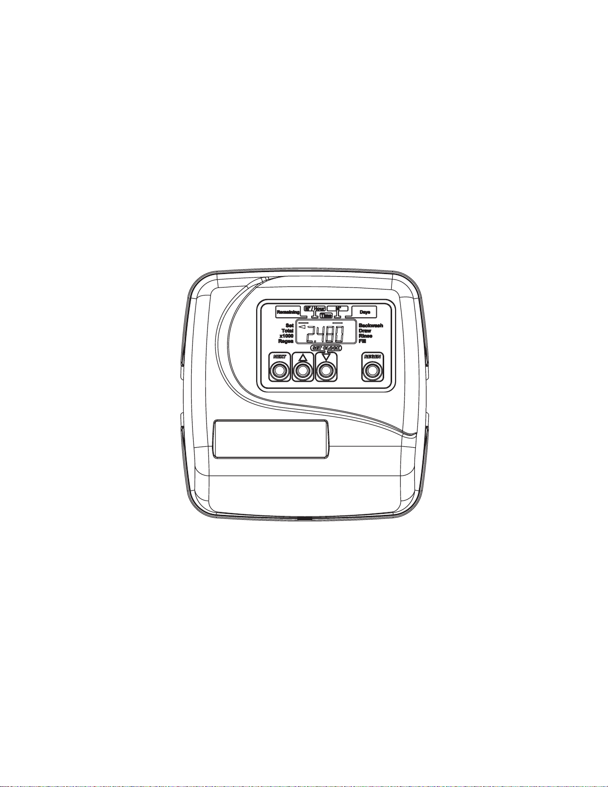
Regen Screen
Displays the time remaining in the
current cycle. Pressing REGEN
advances to the next cycle.
Error Screen
Alternated flashing Err and error
code every 3 seconds. Clear by
dissconnecting the power supply at
the PC board and reconneting, or
press the NEXT and REGEN buttons
simutaneously for 3 seconds.
Regeneration and Error Screens
Button Operation and Function
Scrolls to the next display.
Changes variable being displayed.
Key sequence to lock and unlock
program settings.
Holding for 3 seconds intitiates a control reset. The software
version is displayed and the piston returns to the home/service
position, resynchronizing the valve.
Pressing once and releasing will schedule a regeneration at the preset delayed regeneration time.
Pressing again and releasing will cancel the regeneration.
Pressing and holding for 3 seconds will initiate an immediate regeneration
Pressing while in regeneration will advance to the next cycle.
Pressing in the program levels will go backwards to the previous screen

WS 1.5 EI/2LEI Manual Page 3
User 1
Typical user display. If volume is selected in Configuration
Settings Step 3CS, shows volume remaining to regeneration. If
volume is not selected in Configuration Settings Step 3CS, this
screen will not be shown. If a meter is not used this display will
not change.
User 2
Displays number of days to next regeneration.
User 3
Displays flow rate M3/Hour. If a meter is not used this display
will be shown but 0 will be displayed.
This screen will not be shown if 7 day or 28 day is selected in
Configuration Settings Step 3CS.
User 4
Displays total flow in cubic meters since last reset. If a meter
is not used this display will be shown but 0 will be displayed.
This screen will not be shown if 7 day or 28 day is selected in
Configuration Settings Step 3CS.
PRESS THE DOWN ▼ ARROW
FOR 3 SECONDS TO RESET TO 0.
User 5
Shows current time.
Setting Time of Day
Push NEXT button until time of day screen is displayed. Press and
hold the ▲ or ▼ arrow until the SET indicator is displayed and
the hour flashes. Press the ▲ or ▼ arrow until the correct hour is
displayed.
Then press the NEXT button. The minutes will flash. Press the ▲
or ▼ arrow until the correct minute is displayed.
Press the NEXT button to return to the Display Screens. If the
NEXT button is not pressed Hours or Minutes will flash for five
minutes before returning to Display Screens.
User Displays
General Operation When the system is operating, one of five displays may be shown.
Pressing NEXT will alternate between the displays shown below.

Page 4 WS 1.5 EI/2LEI Manual
Step 2I - Volumetric capacity in cubic meters to
regeneration. Press NEXT to go to Step 3I. Press REGEN
to exit Installer Display.
Step 3I - Adjust day override from 1 - 28 or OFF.
Press NEXT to go to Step 4I. Press REGEN to return to
previous step.
Step 4I - Use ▲or ▼buttons to set the regen hour.
Press NEXT to go to Step 5I. Press REGEN to return to
the previous step.
Installer Display Settings
Step 1I - To enter Installer Display press the NEXT and
▲ buttons simultaneously for 5 seconds and release.
28 Day or 28/Volume (M3) selected in Configuration Settings Step 3CS
Step 1I - To enter Installer Display press the NEXT and
▲ buttons simultaneously for five seconds and release.
Step 2I -Adjust days from 1 - 28. Press NEXT to go to
Step 3I. Press REGEN to exit Installer Display.
Step 3I - Use ▲or ▼buttons to set time of the regen
hour. Press NEXT to go to Step 4I. Press REGEN to return
to previous step.
Step 4I - Use ▲and ▼buttons to set the regen minutes.
Press NEXT to exit Installer Display. Press REGEN to
return to previous step.
One of three sets of displays will be shown depending on what was selected in Configuration Settings Step 3CS.
Volume (M3) selected in Configuration Settings Step 3CS
EXIT TO
DISPLAY
SCREENS
Step 1I
Step 3I
Step 2I
Step 4I
Step 5I
EXIT TO
DISPLAY
SCREENS
Step 2I
Step 3I
Step 4I
Step 1I
Step 5I - Use ▲or ▼buttons to set the regen minutes.
Press NEXT to exit Installer Display. Press REGEN to
return to previous step.

WS 1.5 EI/2LEI Manual Page 5
Step 2I - Use ▲or ▼buttons to set the current day of
the week.
Default = 2 (Monday)
Step 3I - Scroll through days 1 to 7 using the NEXT
button. Use the ▲or ▼buttons to turn regen on or
off for each individual day (regen indicator on means
regeneration will happen). After completing the 7th day,
press NEXT to go to Step 4I. Press REGEN to go to
previous display.
Step 4I - Use the ▲or ▼buttons to set
the regen hour. Press NEXT to go to Step 5I.
Press REGEN to go to previous display.
7 Day or 7/Volume (M3) selected in Configuration Settings Step 3CS
Step 1I - To enter Installer Display press the NEXT and
▲ buttons simultaneously for 5 seconds and release.
1 = SUNDAY
2 = MONDAY
3 = TUESDAY
4 = WEDNESDAY
5 = THURSDAY
6 = FRIDAY
7 = SATURDAY
Press NEXT to go to Step 3I. Press REGEN to exit
Installer Display.
Step 5I - Use the ▲or ▼buttons to set the
regen minutes. Press NEXT to exit Installer
Display. Press REGEN to return to previous
display.
Step 1I
Step 2I
Step 3I
Step 4I
EXIT TO
DISPLAY
SCREENS
Step 5I

Page 6 WS 1.5 EI/2LEI Manual
EXIT TO
DISPLAY
SCREENS
Setting Regeneration Cycle Times
Step 1CT - Press NEXT and ▼simultaneously for 5
seconds and release. If screen in Step 2CT does not appear,
the lock on the valve is activated. To unlock press ▼,
NEXT, REGEN, ▲ in sequence, then press NEXT and ▼
simultaneously for 5 seconds and release.
Step 2CT -Adjust the length of the backwash from 1-20
minutes or OFF using the ▲ or ▼buttons.
Press NEXT to go to Step 3CT. Press REGEN to exit
Regeneration Cycle Times.
Step 3CT -Adjust the length of the regenerant draw
from 1-99 minutes or OFF using the ▲ or ▼buttons.
Press NEXT to go to Step 4 CT. Press REGEN to return
to previous step.
Step 4CT -Adjust the length of the second backwash
from 1-20 minutes or OFF using the ▲ or ▼buttons.
Press NEXT to go to Step 5 CT. Press REGEN to return
to previous step.
Step 5CT -Adjust the length of rinse from 1-20
minutes or OFF using the ▲ or ▼buttons.
Press NEXT to go to Step 6 CT. Press REGEN to return
to previous step.
Step 6CT -Adjust the length of fill from 0.1-99.9
minutes or OFF. Regenerant refills at a rate of 0.5 gpm,
1.9 lpm.
Press NEXT to exit Regeneration Cycle Times. Press
REGEN to return to previous step.
Step 1CT
Step 2CT
Step 3CT
Step 4CT
Step 5CT
Step 6CT

WS 1.5 EI/2LEI Manual Page 7
Configuration Settings
Step 1CS – Press ▲ and ▼buttons simultaneously for 5 seconds and release. If screen in Step
2CS does not appear, the lock on the valve is activated. To unlock press ▼, NEXT, REGEN, ▲in
sequence, then press ▲ and ▼buttons simultaneously for 5 seconds and release.
Step 2CS – Select 25 for 1” (25 mm), 38 for 1.5” (38 mm) or 50 for 2L (50mm). Press NEXT to go
to Step 3CS. Press REGEN to exit Configuration Settings.
Step 3CS – Press the ▲ or ▼buttons to select one of the following:
• If Volume (M3) is selected the regeneration will occur after the specific volume has been
used or on the day override (if selected) whichever comes first.
• If 28 is selected the regeneration will occur on the day (1 through 28) selected in Installer
Display Settings. The total flow and flow rate user displays and the volume display in
Diagnostics will not be shown even if a meter is used.
• If 28/Volume (M3) is selected the regeneration will occur on the day (1 through 28) selected
in Installer Display Settings. If a meter is not used the total flow and flow rate user displays
and the volume display in Diagnostics will be shown as 0.
• If 7 is selected the regeneration will occur on the selected day(s) of the week (see
instructions contained in Installer Display Settings). The total flow and flow rate user
displays and the volume display in Diagnostics will not be shown even if a meter is used.
• If 7/Volume (M3) is selected the regeneration will occur on the selected day(s) of the week
(see instructions contained in Installer Display Settings). If a meter is not used the total flow
and flow rate user displays and the volume display in Diagnostics will be shown as 0.
Press NEXT to go to Step 4CS. Press REGEN to return to previous step.
Step 4CS – Press the ▲ or ▼buttons to select to regenerate immediately on 0 or at delayed time.
Immediately on 0 can only be selected if Volume (M3) was selected in step 3CS and a meter must be
installed. Delay is the only option for the other Step 3CS selections. Press NEXT to go to Step 5CS.
Press REGEN to return to previous step.
Step 5CS – Allows selection of one of the following:
• an outside signal to initiate a regeneration;
• the Control Valve to act as an alternator; or
• the Control Valve to have no hard water bypass.
Selecting the use of an outside signal to initiate a regeneration: Selection only matters if a
connection is made to the two pin connector labeled DP SWITCH located on the printed circuit
board. Following is an explanation of the options:
dPon0 - If the dP switch is closed for an accumulative time of 2 minutes a regeneration will occur
immediately.
dPdEL - If the dP switch is closed for an accumulative time of 2 minutes a regeneration will occur at
the scheduled regeneration time.
HoLd - If the dP switch is closed a regeneration will be prevented from occurring.
Selecting the Control Valve to act as an alternator:
NOTE: In step 3CS you must select Volume, Step 4CS select Regeneration Time Option “on 0” and
in Step 3I select Day Override “oFF.”
Select ALTA for the control valve that has the two pin connector labeled DRIVE connected to the
alternator valve motor.
Select ALTb for the control valve that will not be connected to the alternator valve motor.
Configuring the Control Valve for No Hard Water Bypass Operation: nHbP - Selection requires
that a connection to a Clack Motorized Alternator Valve (MAV) is made to the two pin connector
labeled ALTERNATOR DRIVE located on the printed circuit board. The B port of the MAV must
be plugged and the valve outlet connected to the Aport. The MAV will be driven closed before the
first regeneration cycle that is not FILL or SOFTENING or FILTERING, and be driven open after
the last regeneration cycle that is not FILL.
Press NEXT to exit Configuration Settings. Press REGEN to return to previous step.
Step 1CS
Step 2CS
Step 3CS
Step 4CS
Step 5CS
EXIT TO
DISPLAY
SCREENS

Page 8 WS 1.5 EI/2LEI Manual
Diagnostics
Step 1D
Step 2D
Step 3D
Step 4D
Step 5D
EXIT TO
DISPLAY
SCREENS
Step 1D - Press ▲ and ▼buttons simultaneously for
5 seconds and release. Then press ▲ and ▼buttons
simultaneously for 2 seconds and release. If screen
in Step 2D does not appear the lock on the valve is
activated. To unlock press ▼, NEXT, REGEN, ▲in
sequence, then press ▲ and ▼buttons simultaneously
for 5 seconds and release. Then press ▲ and ▼buttons
simultaneously for 2 seconds and release.
Step 2D - Display shows the number of days since a
regeneration last occurred. Press NEXT to go to Step
3D. Press REGEN to exit Diagnostics.
Step 3D - Display shows the volume of water treated
in M3treated since the last regeneration. If 7 or 28
was selected in Step 3CS this display will not appear.
If Volume (M3), 28/Volume (M3), or 7/Volume (M3)
was selected in Step 3CS and no meter is installed this
display will read 0. Press NEXT to go to Step 4D. Press
REGEN to return to previous step.
Step 4D - Display shows the days in service since start
up. Press NEXT to go to Step 5D. Press REGEN to
return to previous step.
Step 5D - Display shows the total number of
regeneration cycles since start up. Press NEXT to exit
Diagnostics. Press REGEN to return to previous step.

WS 1.5 EI/2LEI Manual Page 9
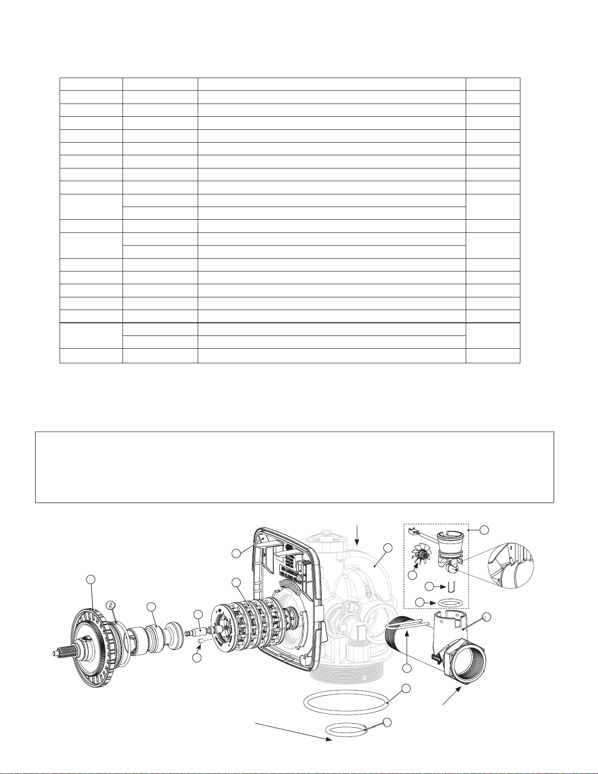
Drawing No. Order No. Description Quantity
1 V3175EI-01 WS1EI FRONT COVER ASSEMBLY 1
2 V3107-01 WS1 MOTOR 1
3 V3106-01 WS1 DRIVE BRACKET & SPRING CLIP 1
4 V3408EI-01BOARD WS1/1.25/1.5/2L EI PC BOARD ALT REPLACE 1
5 V3110 WS1 DRIVE REDUCING GEAR 12X36 3
6 V3109 WS1 DRIVE GEAR COVER 1
Not Shown
V3186 WS1 AC ADAPTER 110V-12V
1
V3186EU WS1 AC ADAPTER 220-240V-12V EU
V3186UK WS1 AC ADAPTER 220-240V-12V UK
V3186-01 WS1 AC ADAPTER CORD ONLY
EI Front Cover and Drive Assembly
1
2
4
5
6
3
AC Adapter U.S. International
Supply Voltage 120 VAC 230VAC
Supply Frequency 60 Hz 50 Hz
Output Voltage 12 VAC 12 VAC
Output Current 500 mA 500 mA
Page 10 WS 1.5 EI/2LEI Manual
WS1.5” Drive Cap Assembly, Downflow Piston, Regenerant Piston, Spacer StackAssembly,
Drive Back Plate, Main Body and Meter
Drawing No. Order No. Description Quantity
1 V3004 WS1 DRIVE CAPASY 1
2 V3135 O-RING 228 1
3 V3407 WS1.5 PISTON DOWNFLOWASY 1
4 V3174* WS1 REGENERANT PISTON 1
5 V3423 WS1.5 BACKPLATE DOWEL 1
6 V3430 WS1.5 SPACER STACK ASY 1
7 V3178 WS1 DRIVE BACK PLATE 1
8 V3419 O-RING 347 1
9V3418 O-RING 328 FOR VALVE BODIES WITH NPT THREADS 1
V3441 O-RING 226 FOR VALVE BODIES WITH BSPT THREADS
Not Shown V3437 WS1.5 FLOW STRAIGHTENER (LOCATED INSIDE METER HOUSING) 1
10 V3401-01 WS1.5 METER HOUSING 1
V3401BSPT-01 WS1.5 METER HOUSING BSPT
11 V3223 WS2 METER CLIP 1
12 V3003-02** WS1.5/2L/2H Meter Commercial Asy 1
13 V3118-03 WS1.5/2 TURBINE ASY 1
14 V3105 O-RING 215 1
15 V3501 WS1.5/2 TURBINE CLIP 1
16 V3400-01 WS1.5 VALVE BODY DOWNFLOW 1
V3400BSPT-01 WS1.5 VALVE BODY DOWNFLOW BSPT
Not Shown D1300 TOP BAFFLE DFSR CLACK 1.5/50MM 1
BSPT threads on inlet and outlet ports on the V3400BSPT-01 and V3401BSPT-01. NPT threads on drain and injector ports on V3400BSPT-01.
*V3174 WS1 Regenerant Piston not used for backwash only valves. V3010-15Z Injector Plug and V3195-01 WS1 Refill Port Plug ASY must be used for
backwash only valves.
**Order number V3003-02 includes V3118-03, V3501 and V3105.
If using a meter on WS1.5” valves, select 1.5 if valve software records in gallons and 38 if valve software records in cubic meters.
1
234
5
6
7
8
9
12
13
B or indent indicates BSPT
N or no mark indicates NPT
Install D1300 upper diffuser (not shown)
In 2007, a u-shaped retaining clip (V3501) was added to commercial meter assemblies to hold the turbine assembly in place. If V3501 is present, service or replace
the turbine by:
1. Removing bend from the two exposed tips of the retaining clip and remove clip.
2. Service or replace the V3118-03 WS1.5/2 TurbineAssembly and place back on the turbine shaft.
3. Insert the V3501 WS1.5/2 Turbine Clip and rebend the exposed tips.
The V3118-03 has a groove to line up with the V3501 WS1.5/2 Turbine Clip. If the meter assembly does not have two holes in the bottom to insert the clip, use a
V3118-01 Turbine Assembly or replace the entire meter.
15
14
10
16
Notch marks appear on hex
if BSPT threads
11

WS 1.5 EI/2LEI Manual Page 11
WS2L Drive Cap Assembly, Downflow Piston, Regenerant Piston, Spacer Stack Assembly,
Drive Back Plate and Main Body
Drawing No. Order No. Description Quantity
1 V3004 WS1 Drive Cap Asy 1
2 V3135 O-ring 228 1
3 V3407 WS1.5 Piston Downflow Asy 1
4 V3174* WS1 Regenerant Piston 1
5 V3423 WS1.5 Backplate Dowel 1
6 V3430 WS1.5 Spacer Stack Asy 1
7 V3178 WS1 Drive Back Plate 1
8 V3419 O-ring 347 1
9V3418 O-ring 328 for valve bodies with NPT threads 1
V3441 O-ring 226 for valve bodies with BSPT threads
Not Shown H1023-03 TubePoly 3/8 x 1/4 Blk 500 Ft. Roll .0006
Not Shown JG-PP481222W Elbow Fix 3/8 x 1/4 NPTF Polypro 2
10 V3453-03 WS2L Body 4-8 NPT w/V3468 Plug 1
V3453BSPT-03 WS2L Body 4-8 BSPT w/V3465 Plug
Not Shown V3468 WS2 Plug 1/4 Hex NPT (included when ordering V3453-03) 2
V3465 WS2 Plug 1/4 Hex BSPT (included when ordering V3453 BSPT-03)
Not Shown D1300 TOP BAFFLE DFSR CLACK 1.5/50MM 1
BSPT threads on inlet and outlet ports on the V3453BSPT-03. NPT threads on drain and injector ports on V3435BSPT-03.
*V3174 WS1 Regenerant Piston not used for backwash only valves. V3010-15Z Injector Plug and V3195-01 WS1 Refill Port
Plug ASY must be used for backwash only valves.
Install D1300 upper diffuser (not shown)
B indicates BSPT
N indicates NPT
10
8
9
1234
6
7
5

Page 12 WS 1.5 EI/2LEI Manual
Drawing No. Order No. Description Quantity
1 V3003-02* WS1.5/2L/2H Meter Commercial Asy 1
2 V3118-03 WS1.5/2 Turbine Asy 1
3 V3105 O-Ring 215 1
4 V3501 WS1.5/2 Turbine Clip 1
5V3222-01 WS2 Meter NPT Housing 1
V3222BSPT-01 WS2 Meter BSPT Housing
6 V3223 WS2 Meter Clip 1
Not Shown V3488 WS2 Flow Straightener (located inside meter housing) 1
1
2
3
5
6
B indicates BSPT
N indicates NPT
MeterAssembly for WS2L Valves
Installation of the WS2 Meter NPTAssembly can be accomplished with 2” NPT pipe or by using a 2½” groove lock coupling. For
WS2 Meter BSPTAssembly use 63mm pipe. When installing the WS2 Meter Assembly it is necessary that the meter be installed
in a horizontal position. After installing the meter, break out the tab in the back plate and thread the meter cord through.
WHEN INSTALLING THE METER, MAKE SURE THE ARROW ON THE METER BODYIS GOING THE SAME
DIRECTION AS THE WATER FLOW.
*Order number V3003-02 includes V3118-03, V3501 and V3105.
4
In 2007, a U shaped retaining clip (V3501) was added to commercial meter assemblies to hold the turbine assembly in place.
If V3501 is present, service or replace the turbine assembly by:
1.Removing bend from the two exposed tips of the retaining clip and remove clip.
2.Service or replace the V3118-03 WS1.5/2 Turbine Assembly and place back on the turbine shaft.
3.Insert the V3501 WS1.5/2 Turbine Clip and rebend exposed tips.
The V3118-03 has a groove to line up with the V3501 WS1.5/2 Turbine Clip. If the meter assembly does not have two holes in
the bottom to insert V3501, use a V3118-01 WS1 Turbine Assembly or replace the entire meter.
Bend clip
after install
Area of
detail

WS 1.5 EI/2LEI Manual Page 13
Injector Cap, Injector Screen, Injector, Plug, Bolts and O-Ring(s)
Drawing No. Order No. Description Quantity
1 V3422 Bolt 3
2 V3403 WS1.5 Injector Cap 1
3 V3417 O-ring 220 1
4
V3010-15B WS1.5 Injector Asy B Violet
1
V3010-15C WS1.5 Injector Asy C Red
V3010-15D WS1.5 Injector Asy D White
V3010-15E WS1.5 Injector Asy E Blue
V3010-15F WS1.5 InjectorAsy F Yellow
V3010-15G WS1.5 Injector Asy G Green
V3010-15H WS1.5 Injector Asy H Orange
V3010-15Z WS1.5 Injector Plug
5 V3404 WS1.5 Injector Screen 1
Not Shown V3171 O-ring 013 *
Not Shown V3416 O-ring 012 *
*The injector or the injector plug each contain one V3416 o-ring 012 (lower) and one
V3171 o-ring 013 (upper).
1
2
3
4
5
Injector Nozzle Color
Injector Throat Black
WS1 & 1.25
INJECTOR
1.730"
1¾” 2.075"
2”
WS1.5
INJECTOR
ALL THROATS ARE
COLORED
AND ALL NOZZLES
ARE WHITE
DO NOT USE ON
WS1.5” VALVES
ALL THROATS ARE
BLACK
AND ALL NOZZLES
ARE COLORED
WS1 & 1.25
INJECTOR PLUG
BLACK
DO NOT USE ON
WS1.5” VALVES
WS1.5
INJECTOR PLUG
GREY
Injector Location on WS2L
Page 14 WS 1.5 EI/2LEI Manual
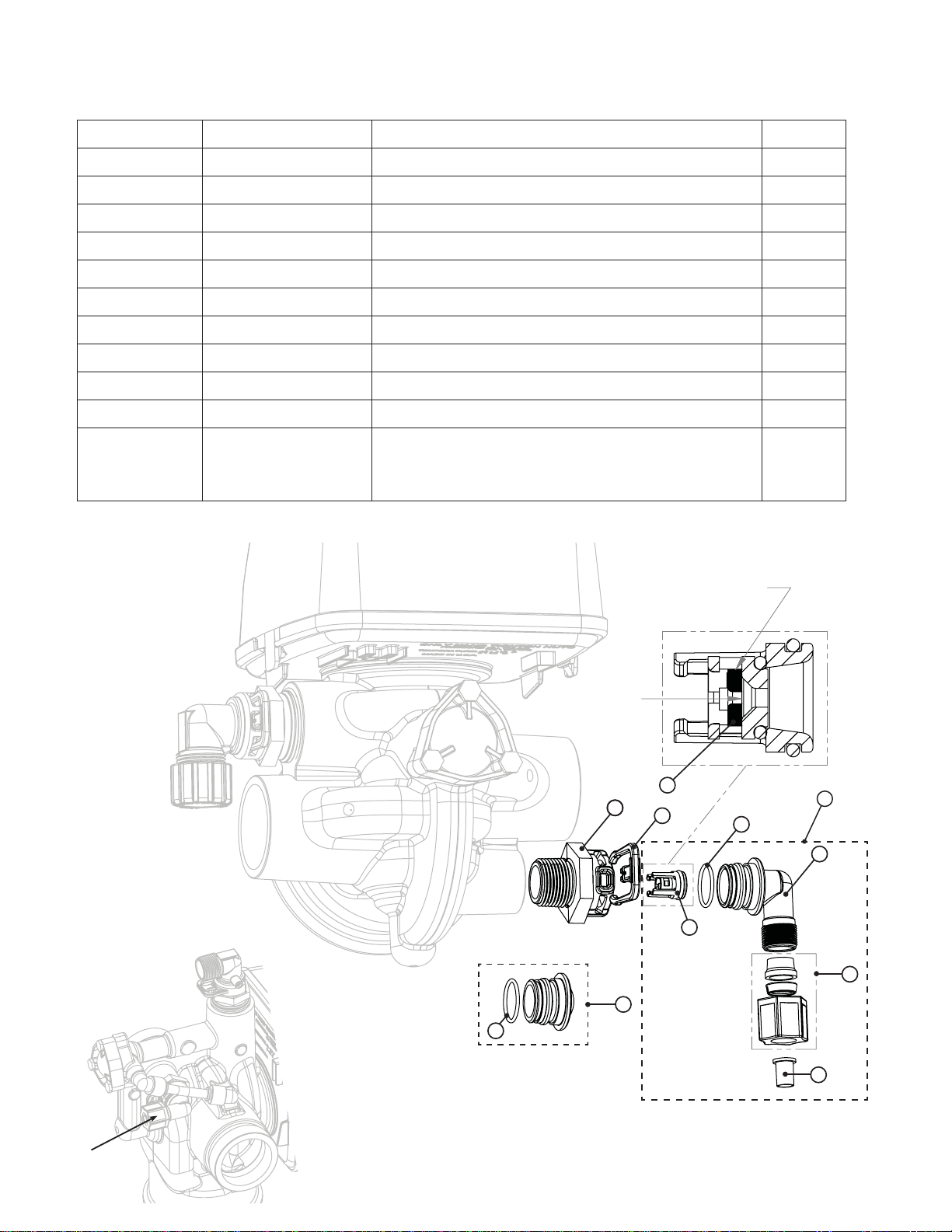
Water Flow
Proper RFC orientation
directs refill water flow
towards the washer face
with rounded edges
12
23
4
5
6
2
7
8
5910
11
1
5
4
10
1
5
9
Refill Flow ControlAssembly and Refill Port Plug
Drawing No. Order No. Description Quantity
1 V3195-01 WS1 Refill Port Plug Asy 1
2 V3415 WS1.5 BLFC Adapter 1
3 H4615 Clip Retaining 1
4 V3428* WS1.5 Refill Retainer ASY 1
5 V3163 O-ring 019 1
6 H4612 Elbow Cap ½” 1
7 JCPG-8PBLK Nut Compression ½” Black 1
8 JCP-P-8 Insert Polytube ½” 1
9 V3182 WS1 RFC 1
10 V3498 WS1.5 Brine Elbow Asy w/RFC ½” Option
Not Shown V3434-01 WS1.5 Refill Asy 5/8 x 3/4 (includes fitting, refill
retainer assembly, o-ring, nut and polytube insert
for 5/8” brine line connection) Option
*V3428 contains a V3182 WS1 RFC
Refill location
on WS2L
10

WS 1.5 EI/2LEI Manual Page 15
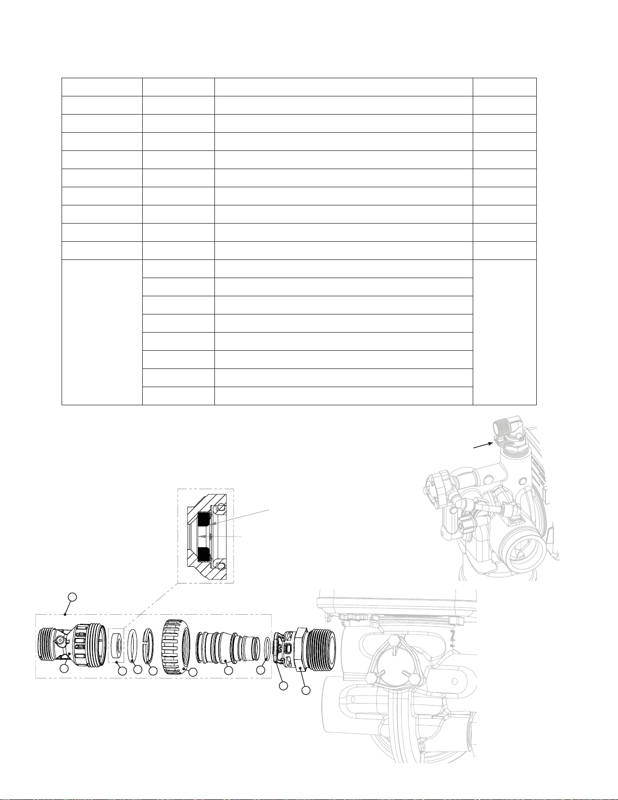
Drain Line ¾”
Drawing No. Order No. Description Quantity
1 H4615 Locking Clip 1
2 V3414 WS1.5 DLFC Adapter 1
3* V3158-01 WS1 Drain Elbow ¾” Male Asy 1
4 V3163 O-ring 019 1
5* V3159-01 WS1 DLFC Retainer Asy 1
6
V3162-032 WS1 DLFC 3.2 gpm (12.1 lpm) for ¾”
One DLFC
must be
used if ¾”
fitting is
used
V3162-042 WS1 DLFC 4.2 gpm (15.9 lpm) for ¾”
V3162-053 WS1 DLFC 5.3 gpm (20.1 lpm) for ¾”
V3162-065 WS1 DLFC 6.5 gpm (24.6 lpm) for ¾”
V3162-075 WS1 DLFC 7.5 gpm (28.4 lpm) for ¾”
V3162-090 WS1 DLFC 9.0 gpm (34.1 lpm) for ¾”
V3162-100 WS1 DLFC 10.0 gpm (37.9 lpm) for ¾”
* 3 & 5 can be ordered as a complete assembly - V3331 WS1 Drain Elbow and Retainer Asy
Valves are shipped without drain line flow control (DLFC) – install DLFC before using. Use a minimum
drain line size of ¾”.
3
45612
Drain Line location on WS2L
Page 16 WS 1.5 EI/2LEI Manual
Drain Line 1”
Drawing No. Order No. Description Quantity
1 H4615 Locking Clip 1
2 V3414 WS1.5 DLFC Adapter 1
3 V3008-02 WS1 Drain Ftg 1” Straight 1
4* V3163 O-ring 019 1
5* V3167 WS1 Drain Ftg Adapter 1” 1
6* V3151 WS1 Nut 1” QC 1
7* V3150 WS1 Split Ring 1
8* V3105 O-ring 215 1
9* V3166 WS1 Drain Ftg Body 1” 1
10
V3190-090 WS1 DLFC 9.0 gpm (34.1 lpm) for 1”
One
DLFC
must be
used if 1”
fitting is
used
V3190-100 WS1 DLFC 10.0 gpm (37.9 lpm) for 1”
V3190-110 WS1 DLFC 11.0 gpm (41.6 lpm) for 1”
V3190-130 WS1 DLFC 13.0 gpm (49.2 lpm) for 1”
V3190-150 WS1 DLFC 15.0 gpm (56.8 lpm) for 1”
V3190-170 WS1 DLFC 17.0 gpm (64.4 lpm) for 1”
V3190-200 WS1 DLFC 20.0 gpm (75.7 lpm) for 1”
V3190-250 WS1 DLFC 25.0 gpm (94.6 lpm) for 1”
* Can be ordered as a set, order number V3008-02 WS1 Drain Ftg 1” Straight
Water Flow
Proper DLFC orientation
directs water flow towards
the washer face with
rounded edge
9
3
10 87654
12
Drain Line location on WS2L
WS 1.5 EI/2LEI Manual Page 17
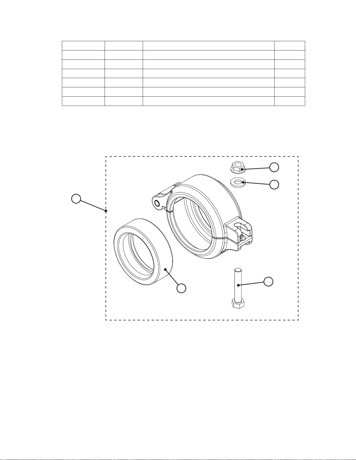
V3053 WS2 2-1/2 GROOVELOCK CLAMPASY
Drawing No. Order No. Description Quantity
1 V3053 WS2 2-1/2 GROOVELOCK CLAMPASY 1
2 V3290 WS2 GROOVE LOCK SEAL 2.5 1
3 V3269 WS2 NUT 5/16-18 SS HEX 1
4 V3293 WS2 WASHER SS 5/16 FLAT 1
5 V3276 WS2 BOLT HEX SS 5/16-18X1-3/4 1
Not Shown S3086 SILICONE LUBRICANT 1
1
3
4
5
2

Page 18 WS 1.5 EI/2LEI Manual

WS 1.5 EI/2LEI Manual Page 19

Page 20 WS 1.5 EI/2LEI Manual
Form No. V3435EI – 9/28/07
Revision History:
7/30/07
PAGE 7:
Step 5CS
8/9/07
PAGE 7:
Selecting the Control Valve to act as an alternator:
NOTE: In step 3CS you must select Volume, Step 4CS select Regeneration Time Option “on 0” and in Step
3I select Day Override “oFF.”
Select ALTA for the control valve that has the two pin connector labeled DRIVE connected to the alternator
valve motor.
Select ALTb for the control valve that will not be connected to the alternator valve motor.
PAGE 10 & 12:
Update Turbine Asy part number V3118-03 and Turbine Asy drawing.
9/10/07
PAGE 7:
Added reference to all valve versions
PAGE 9:
Added AC Adapter Table.
V3110 WS1 DRIVE REDUCING GEAR 12x36
9/28/07
This manual suits for next models
3
Table of contents
Other Wetco Control Unit manuals


