MidNite Solar Classic 150 User manual

49
Directions for equalizing the solar panel using the
MIDNITE Solar Classic 150 Charge Controller
1. Check programmed absorb, equalize, and float voltages
Note: These values should already be set to the correct values
according to the manual
1. Repeat presses of the “Main Menu” until “Charge” is highlighted
2. Press “Enter”
3. Highlight “Volts”
4. Press “Enter”
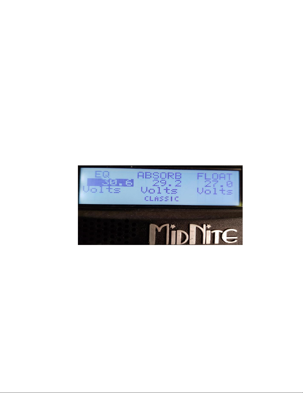
5. Make sure the Equalize, Absorb, and Float voltages are 30.6 V, 29.2 V, and
27.0 V respectively.
Figure A.1: Programmed Voltage Settings
6. If the voltages do not match up, highlight the values and adjust them
accordingly using the up and down arrow keys.
7. Press “Enter” to save the values
8. Press “Status” to return to the home screen
2. Check programmed equalization time
1. Repeat presses of the “Main Menu” until “Charge” is highlighted
2. Press “Enter”
3. Scroll to the right and highlight “ChgTime”
4. Press “Enter”

50
5. Make sure the time under “EQ” is 2:00, indicating the equalizing process
will be two hours long
Figure A.2: Equalization Time
6. If the programmed time is not two hours, scroll to the right and highlight the
time under “EQ”
7. Adjust the equalizing time using the up and down arrow keys
8. Press “Enter” to save the time
9. Press “Status” to return to the home screen
3. Disconnect DC and AC loads
1. Check that the battery system is fully charged
Figure A.3: Battery Status

51
2. Turn off the circuit breaker for the kitchen freezer and the kitchen lights
inside the breaker box next to the kitchen door
Figure A.4: Kitchen Freezer and Lights Circuit Breakers
3. Turn off the circuit breakers for the solar panel and the charge controller
connections inside the breaker box next to the power inverter
Figure A.5: Solar Panel Circuit Breaker

52
4. Start manual equalization
1. Repeat presses of the “Main Menu” until “Charge” is highlighted
2. Press “Enter”
3. Scroll down and highlight “EQ”
4. Press “Enter”
5. “EQ Stopped” will be highlighted
6. Scroll up to select “EQ Started”
7. Equalization process starts when “EQ Started” is highlighted
Figure A.6: Equalization Start Interface
8. Press “Status” to return to home screen
9. On the home screen, the bottom right corner should say EQ
10.To stop a manual equalization process, reverse the steps above and make
sure “EQ Stopped” is highlighted
11. Equalization will stop when the programmed time has come to an end
5. Reconnect loads
1. Switch back on all the disconnected loads done in Step 3: Disconnect DC
and AC loads

53
Operation manual for the PROwatt SW 1000 Sine Wave
Inverter
Figure A.7: User Interface
1. Turning the inverter on and off
1. Press the power switch button for half a second to turn on the inverter
2. Press the power switch button for one second to turn off the inverter
3. If you are not planning on recharging the battery within a week or so, turn
the inverter off
2. Indicator LEDs
1. If the green LED is on, the unit is on and the AC outlets and USB port have
power
2. If the red LED is on, an error code is displayed underneath on the digital
display
3. Digital Display

54
1. Under normal operating conditions, the green LED is on and the digital
display shows the input voltage (volts) and the outpower (kilowatts)
2. Under error or alarm conditions, the digital display shows an error code and
the red LED turns on
Description of LED and Digital Display Codes
LED
Digital Display
Description
Green
13.5
Example: 13.5 Volts
Green
0.25
Example: 0.25 kW (250 Watts)
Red
E01
Under voltage alarm/shutdown
Red
E02
Over voltage shutdown
Red
E03
Over load shutdown
Red
E04
Over temperature shutdown
Red
E10
Short circuit or output overheat
Table A.1: LED and Digital Display Codes
Operating Limits: Input Voltages
Operating Condition
Voltage Range
Comment
Normal
10.5 - 15.5 V
N/A
Peak Performance
13 - 14.5 V
N/A
Low Voltage Alarm
< 11.0 V
Alarm sounds
Low Voltage Shutdown
< 10.5 V
Unit shuts down
High Voltage Shutdown
> 15.5 V
Unit shuts down
Low Voltage Shutdown Restart
11.5 V
Unit will restart
Table A.2: Voltage Operating Limits
After a shutdown, restart the system by turning the device off and letting the unit
cool down for 15 minutes before turning the device back on

55
Figure A.8: Power Inverter GFCI Outlet
4. Ground Fault Circuit Interrupter (GFCI) Outlet Testing
1. Turn on the power inverter
2. Plug a device, such as a lamp, into the AC outlet
3. Push the Test button
•The reset button should pop out and the power should turn off. For
example, if the lamp goes out, it is functioning correctly. If the lamp
remains lit, or the reset button does not pop out, the GCFI may not be
functioning
•If the GCFI trips by itself at anytime, reset it and perform the test
again
5. Maintenance
1. Clean the exterior of the unit with a damp cloth periodically to prevent the
accumulation of dust and dirt
2. Tighten the screws on the DC input terminals periodically

56
Figure A.9: Power Inverter DC Terminals

57
Troubleshooting Reference for the PROwatt SW 1000
Sine Wave Inverter
Troubleshooting Reference
Condition
Possible Cause
Solution
E01
Under voltage shutdown
Recharge battery and check
connections
E01 with persistent low
battery alarm
Poor DC wiring/ battery
condition
Use proper and secure wiring;
charge or install new battery
E02
Over voltage shutdown
Check if connected to 12 V
battery system
E03
Overload shutdown
Reduce load
E04 with heavy load
connected
Over temperature shutdown
Cool down inverter and reduce
load
E04 with normal load
connected
Over temperature shutdown
Improve ventilation
E10 no output voltage
Short circuit; heavy load;
output circuit overheat
Check for short circuit; remove
load; turn unit off and cool
No output voltage; no
voltage indication
Unit is off; No power to
inverter; Inverter fuse open;
Reverse DC polarity
Turn device on; check wiring;
replace fuse if necessary; check
polarity
Unit is on but no AC output
GFCI device tripped
Reset the GCFI
Table A.3: Power Inverter Troubleshooting Reference

58
Operation manual for the JW-MPPT 2.0 high-end wind
solar hybrid charge controller
Figure A.10: Charge Controller User Interface
1. Shown battery voltage (should be around 12 Volts)
2. Indicates time of day (should have no influence on functionality)
3. Digital display of the battery voltage
4. Represents the wind turbine providing power generation (if there is a solar panel
connected, there will be a solar panel icon)
5. Represents the battery
•If there are arrows to the left of the battery, it represents charging from icon
4
•If there are arrows to the right of the battery, it represents discharging and
powering the load indicated in icon 6

59
6. Load icon, there will be lighting effects in the bulb when there is an output to the
load
7. Charge LED (refer to the table below)
8. Output LED (refer to the table below)
9. Button interface
•Enter: Press this button to enter setup interface or switch between programs
•Up arrow: Use this to increase parameter values by increments of 0.1
•Down arrow: Use this to decrease parameter values by increments of 0.1
•Esc: Press this button to exit the setup interface and save the modified
parameters
Table A.4: LED Reference
Maintenance
1. Clean the exterior of the unit with a damp cloth periodically to prevent the
accumulation of dust and dirt
2. Ensure that the terminal screws for the wires are not loose
3. Ensure that the voltage of the battery is around 12 volts
4. Ensure that the float voltage is around 13.8 volts
Figure A.11: Float Voltage Reference
5. Ensure that the under voltage is around 10.8 volts

60
Figure A.12: Under Voltage Reference
6. Ensure that the over voltage is around 15.0 volts
Figure A.13: Over Voltage Reference
Table of contents
Other MidNite Controllers manuals
Popular Controllers manuals by other brands

National Instruments
National Instruments NI cDAQ-9134 SAFETY, ENVIRONMENTAL, AND REGULATORY INFORMATION

Phytec
Phytec L-856e.A1 phyBOARD-Mira quick start

PS Automation
PS Automation PSQ-E130 operating instructions

Omron
Omron HOME SECURITY SYSTEM - MOTION SENSOR... Operation manual

Lynxspring
Lynxspring ONYXX LX BZ424-LX Installation and wiring guide

Omron
Omron E5DC-SCT1S instruction manual