Midwest Industries ShoreStation SSV60120EAC User manual
Midwest Industries, Inc. Ida Grove, IA 51445 800.859.3028 www.shorestation.com 0003853
PAGE 1 09/06/07
SSV60120EAC & SSV60120EACDW
SSV60120EAC Hoist Alum SS V-Frame - EAC
68204 Hardware Box - SSV60120 Hoist
62683 Lower Frame Bundle - SSV60120
62866 Platform Bundle - SSV60120
6941701 Winch Assembly - AC 6000 lb Hoist
69626 Winch Tube Bundle - SSV60120
68203 Leg Bundle - SSV60120
HA0024 Motor Stop Bundle Alum 5” V-Frame
HA0021 Bunk Poly V40H-60108/120 - 60132H
69631 Lit Packet, V60120EAC/DW
NOTE: When referencing the front of hoist, this represents the winch end. When referencing the hoist end, this represents opposite of the
winch end. Which side is also referred to the right side of the hoist.
SSV60120EAC DW Hoist Alum SS V-Frame - EAC
68204 Hardware Box - SSV60120 Hoist
62683 Lower Frame Bundle - SSV60120
62866 Platform Bundle - SSV60120
6941701 Winch Assembly - AC 6000 lb Hoist
69626 Winch Tube Bundle - SSV60120
68206 Leg Bundle - SSV60120DW
HA0024 Motor Stop Bundle Alum 5” V-Frame
HA0021 Bunk Poly V40H-60108/120 - 60132H
69631 Lit Packet, V60120EAC/DW
Midwest Industries, Inc. Ida Grove, IA 51445 800.859.3028 www.shorestation.com 0003853
PAGE 2 09/06/07
Midwest Industries, Inc. Ida Grove, IA 51445 800.859.3028 www.shorestation.com 0003853
PAGE 3 09/06/07
Midwest Industries, Inc. Ida Grove, IA 51445 800.859.3028 www.shorestation.com 0003853
PAGE 4 09/06/07

Midwest Industries, Inc. Ida Grove, IA 51445 800.859.3028 www.shorestation.com 0003853
PAGE 5 09/06/07
Midwest Industries, Inc. Ida Grove, IA 51445 800.859.3028 www.shorestation.com 0003853
PAGE 6 09/06/07
Midwest Industries, Inc. Ida Grove, IA 51445 800.859.3028 www.shorestation.com 0003853
PAGE 7 09/06/07
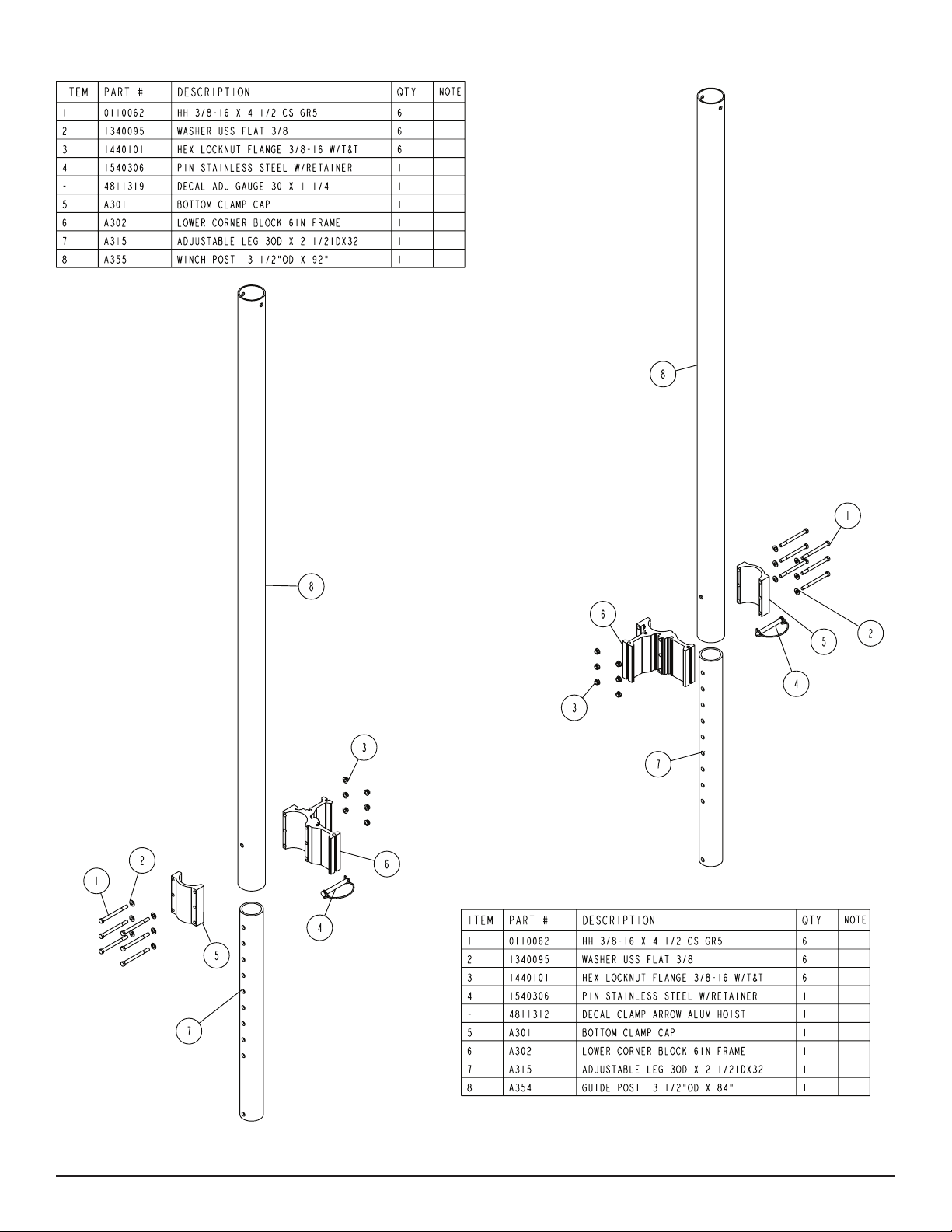
Winch Post Guide Post
Midwest Industries, Inc. Ida Grove, IA 51445 800.859.3028 www.shorestation.com 0003853
PAGE 8 09/06/07
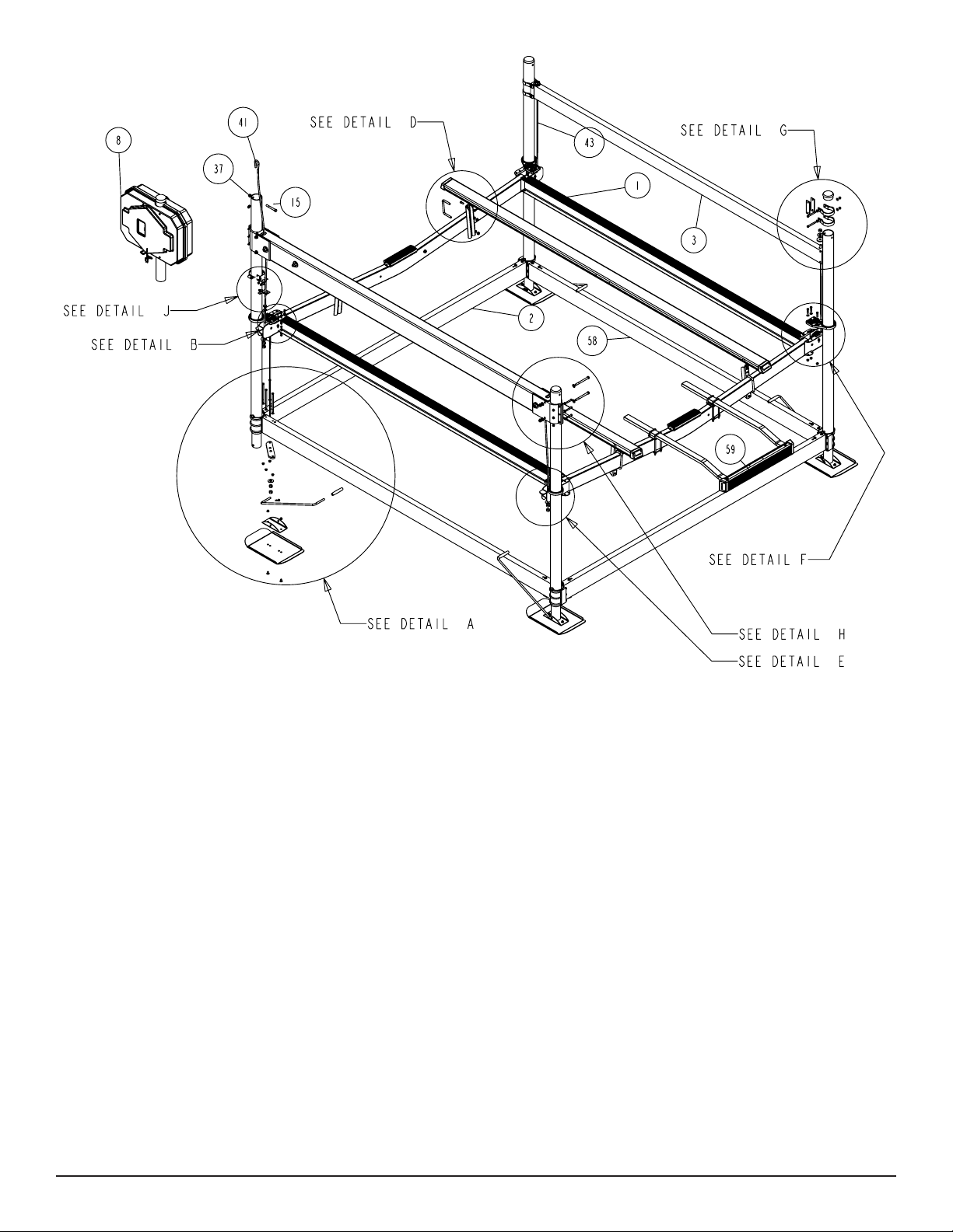
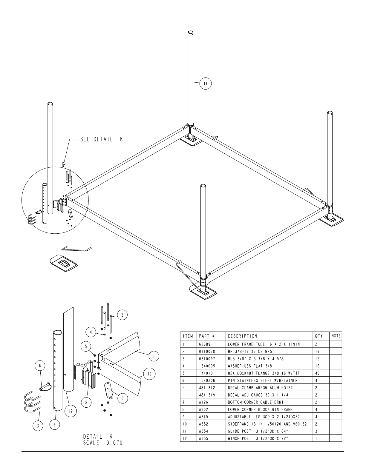
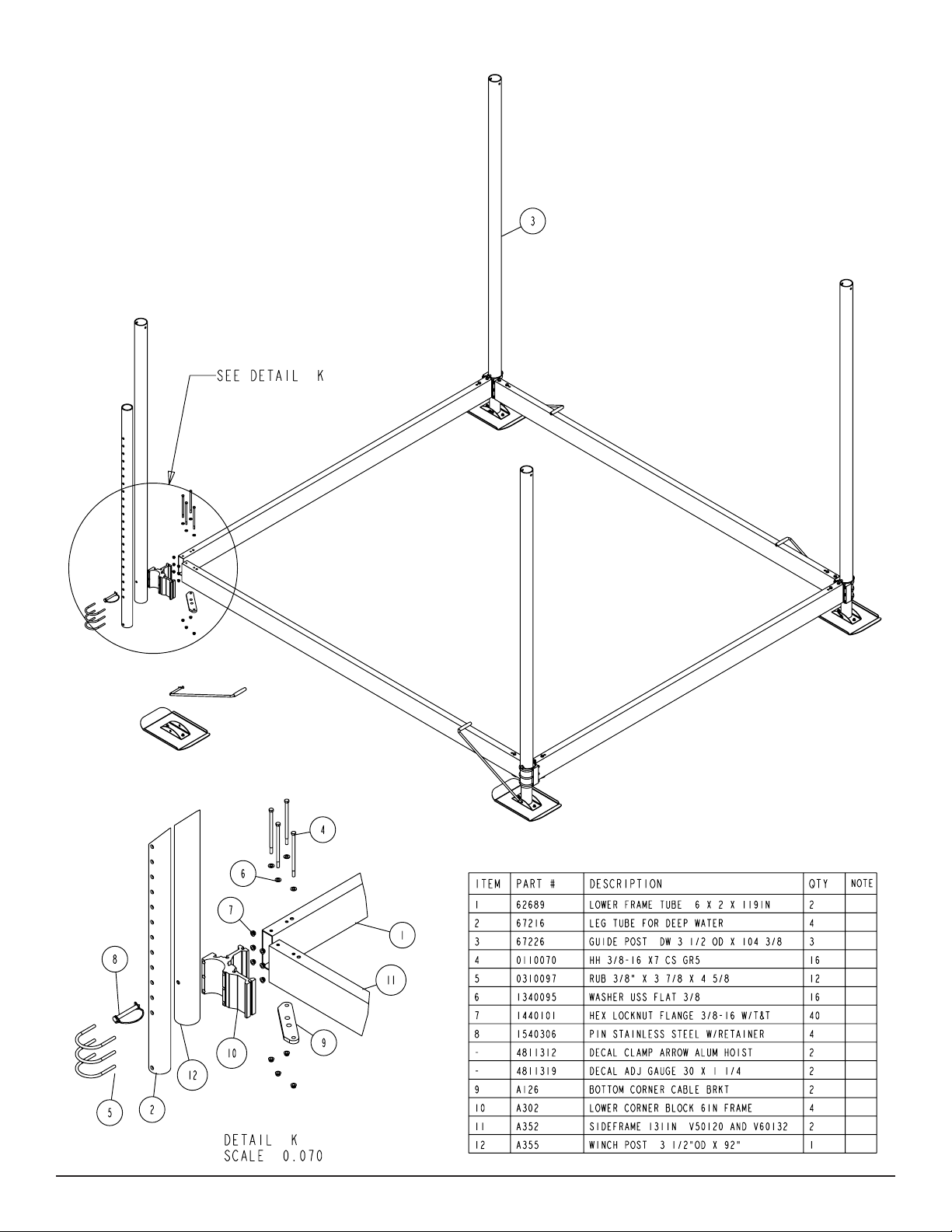
Lower Frame Assembly

Midwest Industries, Inc. Ida Grove, IA 51445 800.859.3028 www.shorestation.com 0003853
PAGE 9 09/06/07
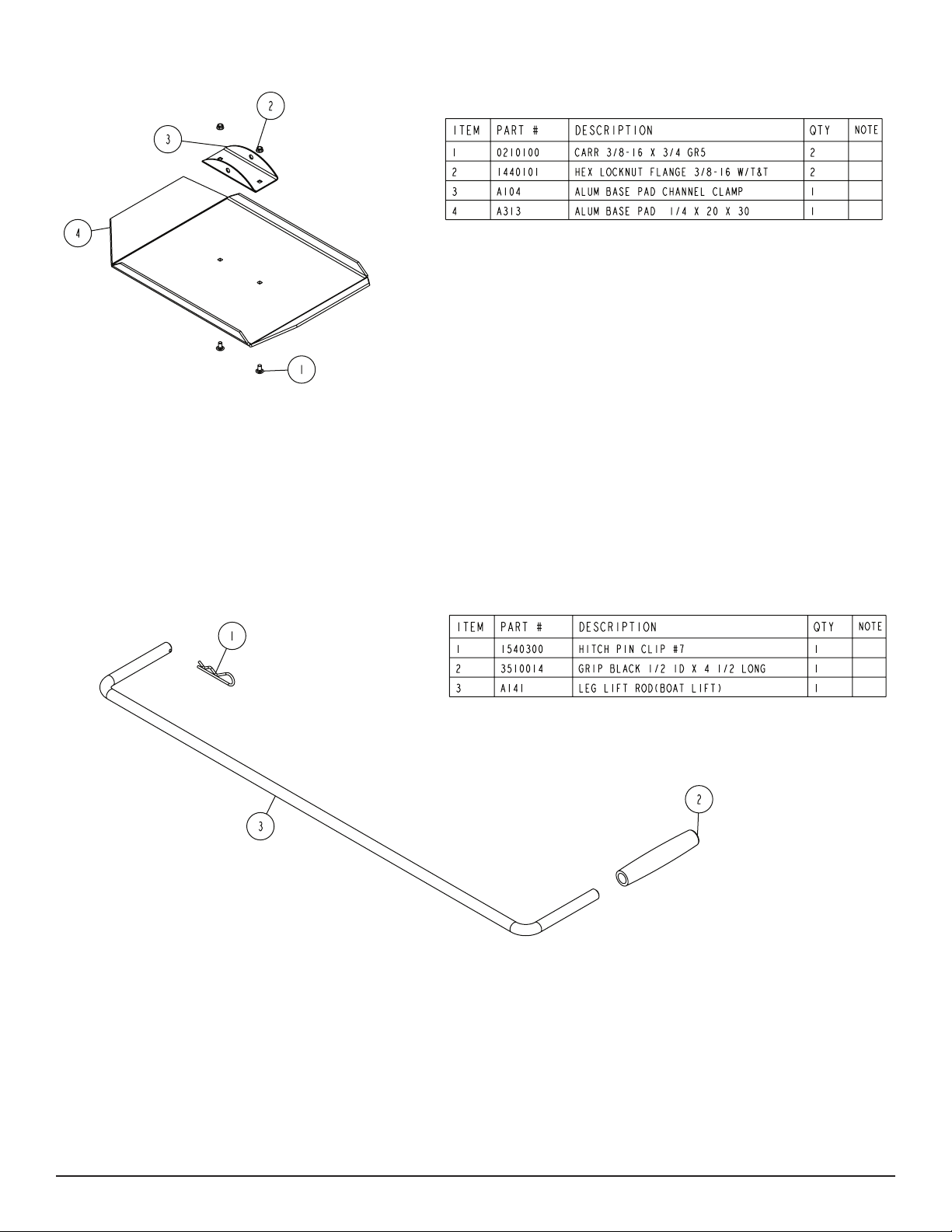
Platform Assembly

Midwest Industries, Inc. Ida Grove, IA 51445 800.859.3028 www.shorestation.com 0003853
PAGE 10 09/06/07
Winch Tube
WINCH TUBE SERVICE INSTRUCTIONS
The winch tube assembly was pre-assembled at the factory.
It is important that the internal parts and cable routings are
assembled properly in order for the winch tube assembly to
function properly. It also requires special tools during the as-
sembly process. It is therefore recommended that you con-
tact your local dealer should you ever have issues with the
winch tube assembly.
Midwest Industries, Inc. Ida Grove, IA 51445 800.859.3028 www.shorestation.com 0003853
PAGE 11 09/06/07
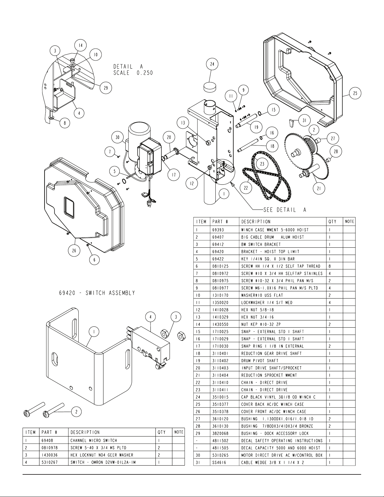
AC Drive Winch Assembly
Midwest Industries, Inc. Ida Grove, IA 51445 800.859.3028 www.shorestation.com 0003853
PAGE 12 09/06/07
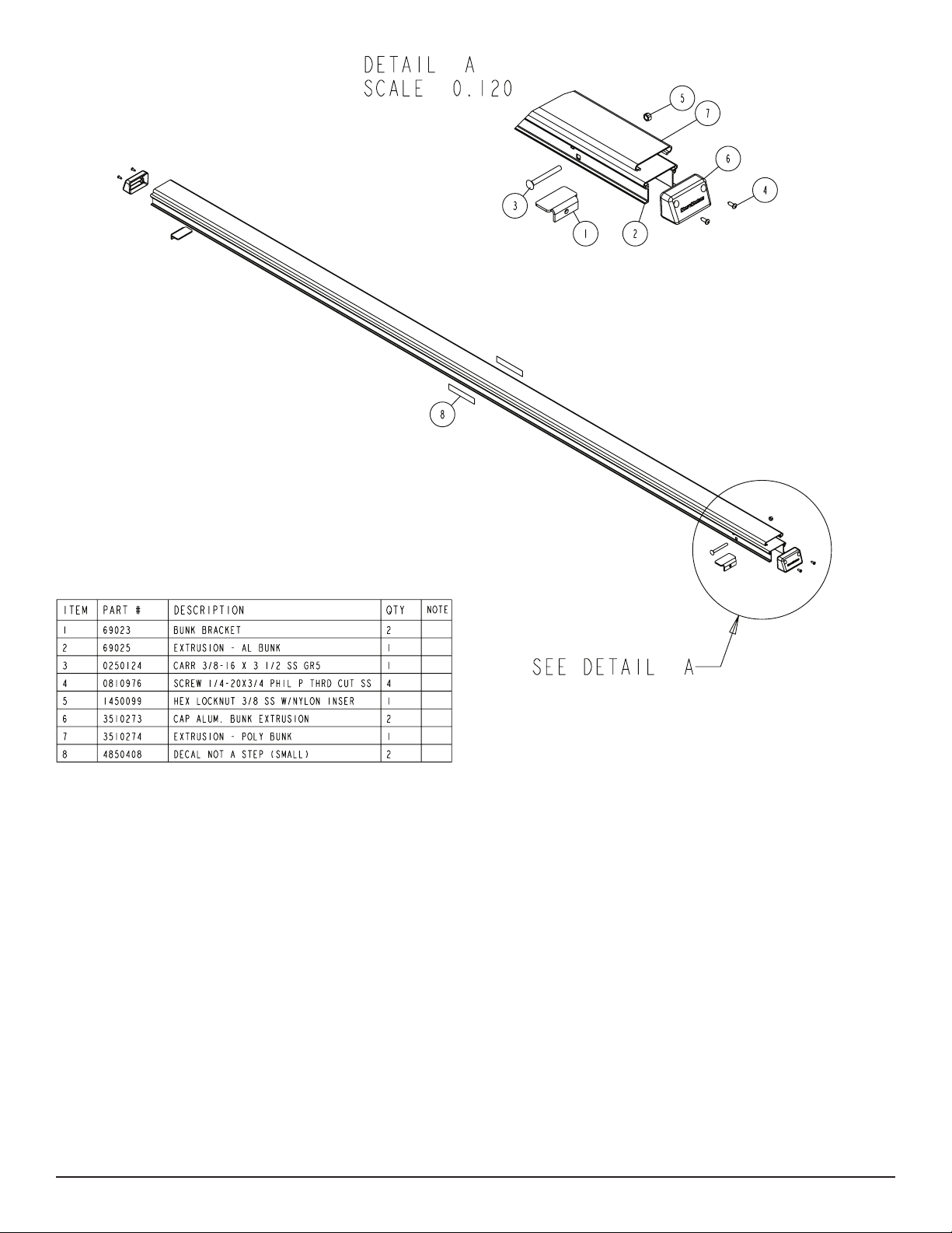
Bunk Assembly
Midwest Industries, Inc. Ida Grove, IA 51445 800.859.3028 www.shorestation.com 0003853
PAGE 13 09/06/07
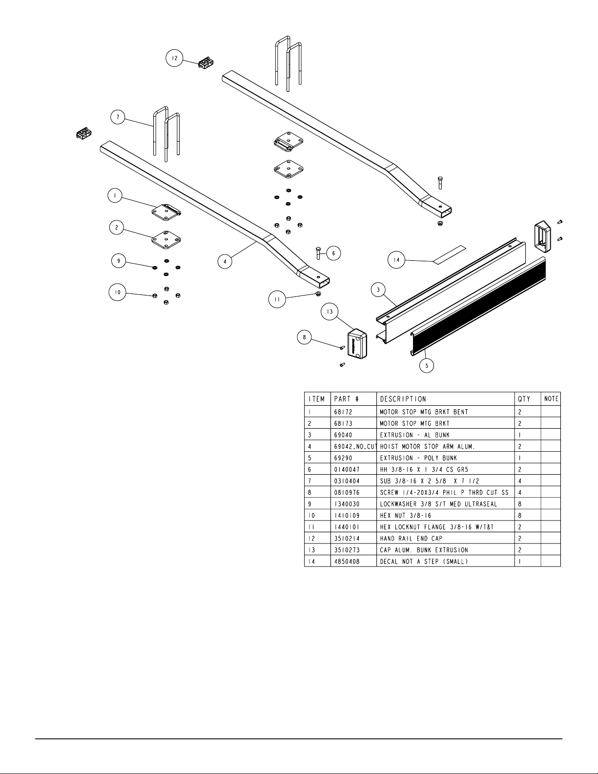
HA0024 - Motor Stop
Assembly Instructions
Locate the two motor stop mounting arms (Item #4) and the motor
stop assembly that is pre-assembled at the factory.
Note that the aluminum extrusion in the motor stop assembly has
two holes pre-drilled in one leg of the extrusion. Position the motor
stop assembly so that the drilled leg is to the top as shown. Locate
a 3/8” x 1 ¾” hex bolt and drop it into the hole in the top leg of
the aluminum extrusion. Position the motor stop mounting arm as
shown so that it is on the bottom side of the top leg of the alumi-
num extrusion. Align the hole in the end of the motor stop mounting
arm with the bolt just installed. Insert the bolt through the hole in
the motor stop mounting arm. Secure with a 3/8” ange lock nut.
Tighten. Tap the black plastic caps into the other end of the motor
stop mounting arms.
Repeat step three on the remaining motor stop mounting
arm.
Installation
Locate the two hoist motor stop U-bolt brackets with the
offset (Item #1) and position them as shown in the diagram on the
top side of the hoist platform so they are spaced correctly to t the
motor stop assembly. The offset must be placed as shown to com-
pensate for the V-shape in the platform.
Place the motor stop assembly on the two hoist motor
stop U-bolt brackets with offset just positioned. Drop the
3/8” x 2 5/8” x 7 ½” U-bolts over the motor stop mounting
arms, then down through the holes provided in the motor
stop U-bolt brackets with the offset.
Push the U-bolts all the way down until the tops of the
U-bolts are resting on the motor stop mounting arms.
Place a straight motor stop U-bolt bracket on the U-bolt
legs on the bottom side of the platform. Secure in place
with 3/8” lock washers and hex nuts. Hand tighten only at
this point.
Repeat steps 5, 6 and 7 on the other motor stop mounting
arm.
Adjustment
Position the hoist motor stop assembly on the hoist so it
is centered side to side on the hoist platform. Changing
the motor stop location front to rear is accomplished by
sliding the straight portion of the motor stop arm through
the U-bolts. This allows you to change the motor stop
location to best position your boat on the hoist. Once the
assembly is in the proper position, tighten the nuts on the
U-bolts.
Midwest Industries, Inc. Ida Grove, IA 51445 800.859.3028 www.shorestation.com 0003853
PAGE 14 09/06/07
DW (Deep Water) SECTION:

Midwest Industries, Inc. Ida Grove, IA 51445 800.859.3028 www.shorestation.com 0003853
PAGE 15 09/06/07
The deep water version of this boat hoist is assembled using
the same assembly instructions as the standard hoist. The
only items that are different between the two hoists are the
length of the upright corner posts and the adjustable legs in-
side them as identied in the drawings for deep water legs.
The water depth where your hoist is going to be installed will
determine whether you should use the deep water version
of this hoist.
The deep water version of this hoist can be used in deeper
water depths because of the additional length of the exten-
sion legs. Listed below is the amount of adjustment the vari-
ous legs have.
• A standard leg shipped with the hoist has 20” of
adjustment.
• The deep water legs have 55” of adjustment.
Midwest Industries, Inc. Ida Grove, IA 51445 800.859.3028 www.shorestation.com 0003853
PAGE 16 09/06/07
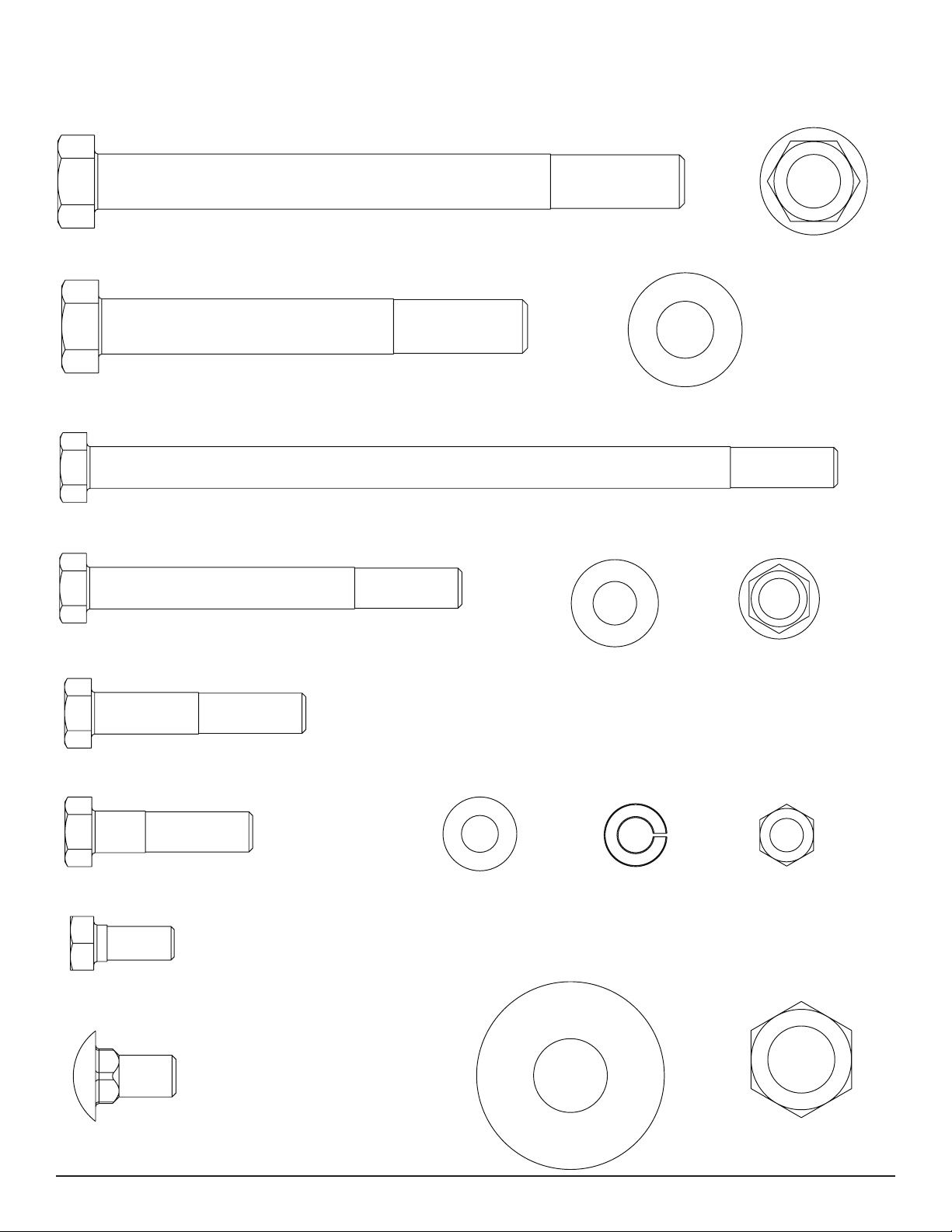
1/2”X 5-1/2”Hex Bolt - Qty: 4 (0110125)
1/2”X 4”Hex Bolt - Qty: 1 (0110114)
3/8”X 7”Hex Bolt - Qty: 16 (0110070)
3/8”X 3-1/2”Hex Bolt - Qty: 4 (0110058)
3/8”X 2”Hex Bolt - Qty: 6 (0110048)
3/8”X 1-1/2”Hex Bolt - Qty: 13 (0110045)
5/16”X 3/4”Hex Bolt - Qty: 16 (0140022)
3/8”X 3/4”Carriage Bolt - Qty: 8 (0210100)
1/2”Flange Lock Nut
Qty: 5 (1440102)
1/2”Flat Washer
Qty: 8 (1340100)
3/8”Flat Washer
Qty: 60 (1340095)
3/8”Flange Lock Nut
Qty: 48 (1440101)
5/16”Lock Washer
Qty: 16 (1310025)
5/16”Flat Washer
Qty: 16 (1310085)
5/16”Hex Lock Nut
Qty: 16 (1410079)
5/8”Flat Washer
Qty: 6 (1340105) 5/8”Brass Hex Nut
Qty: 10 (1410362)
0160042 Pre-Packaged Hardware Bag

Midwest Industries, Inc. Ida Grove, IA 51445 800.859.3028 www.shorestation.com 0003853
PAGE 32 09/06/07
4850408
Not A Step Decal
4811312
Clamp Arrow Decal
4811319
Adj. Guage Decal
4811505
Max Load
Decal
4850363
Safety Decal
4811312
Clamp Arrow Decal
4811319
Adj. Gauge Decal
4811502
Safety Operating Decal
4850394
Max Load Decal
4850408
Not A Step Decal
SSV60120EAC Decal Placement
4811505 Maximum Load Decal - Winch Assy
4811502 Safety Operating Decal
4811312 Clamp Arrow Decal
4811319 Adj. Gauge Decal
4850363 Safety Decal
4850408 Not A Step Decal
4850394 Maximum Load Decal - Winch Tube
This manual suits for next models
1


