Midwest ShoreStation CF24-120N User manual

Midwest Industries, Inc. Ida Grove, IA 51445 800.859.3028 www.shorestation.com 0003526
Page 1 REV A 4/12/06
CF24-120N, CF26-120N & CF30-120N Canopy Frames Fitting:
Aluminum Hoist Models: SSV30/40120, SSPV30/40120, SS30/40120 DW,
SSPV30/40120 DW, SSV50120 & SSV50120 DW
Hydraulic Hoist Models: SSV40120 HYD, SSV60120 HYD, SSV40120 HYD DW &
SSV60120 HYD DW
Steel Hoist Model: SSV45120
Diagram A
Midwest Industries, Inc. Ida Grove, IA 51445 800.859.3028 www.shorestation.com 0003526
Page 2 REV A 4/12/06
Diagram B

Midwest Industries, Inc. Ida Grove, IA 51445 800.859.3028 www.shorestation.com 0003526
Page 3 REV A 4/12/06
ASSEMBLY INSTRUCTIONS
Break bundles and hardware box. Sort all parts according to
size. Depending on the model ordered, you may have extra
parts.
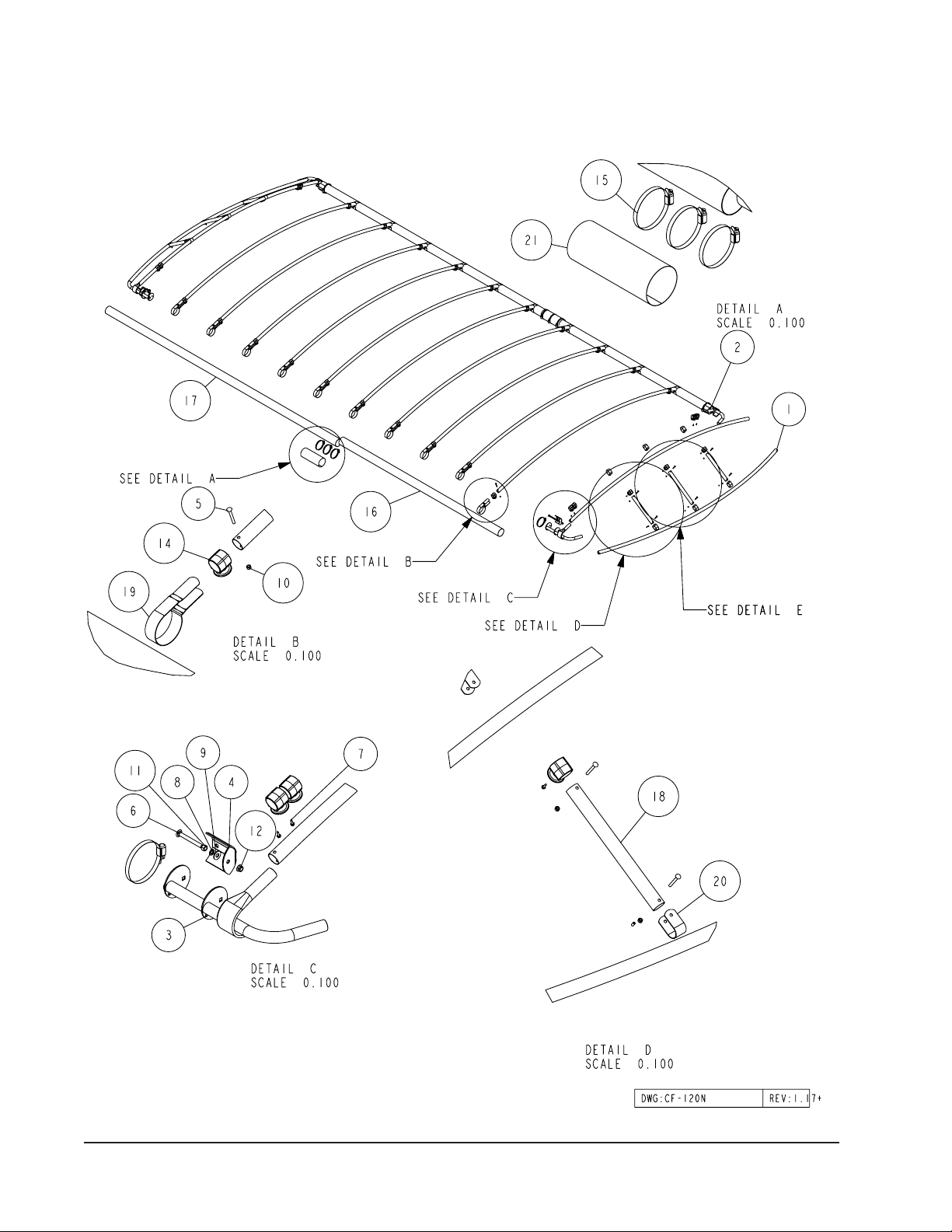
END HOOD ASSEMBLY
(Refer to Diagram A for a final assembly view)
The first step will be to assemble the end hoods. Locate
the adjustable canopy end assemblies. Note that there are
two- right and two- left hand assemblies. (See Diagram B,
Detail E.)
Next locate two of the canopy bows and place them on the
floor or ground with one each of the right and left hand as-
semblies placed at each end of the bows.
Identify the canopy bow that will be installed as the bow that
will form the upper curved portion of the canopy end section.
Slide two (2) each of the plastic canopy cord spool hooks on
each end of this canopy bow. A total of four canopy cord spool
hooks will be placed on this bow.
Insert one end of the two canopy bows over the round tubes
on one of the adjustable canopy end assemblies. Note that
one bow will lay flat on the floor while the other bow with the
canopy cord spool hooks installed will curve upward in the
form of the canopy once it is completely assembled.
Insert the other ends of the canopy bows onto the round tubes
on the second adjustable end assembly. Make sure that the
canopy bows are slid onto the round tubes as far as they can
without jamming or driving them on.
Mark the centers on the two canopy bows. Locate one of the
19” canopy end spacer tubes (Item 22 in Diagram B, Detail
E). Attach it to the canopy bow that is laying flat on the floor
or ground at the center location just marked. Secure together
with an end hood loop using a 1/4” x 2-1/4” carriage bolt and
nut provided as shown. Slip one of the canopy cord spool
hooks onto the 19” canopy end spacer tube. Secure the
other end of the spacer tube to the top bow with a second
end hood loop and 1/4” x 2-1/4” carriage bolt. Secure with a
¼” hex nut. Tighten.
Locate one of the 16” canopy end spacer tubes (Item 18 in
Diagram B, Detail D). Attach it to the canopy bow that is laying
flat on the floor or ground at the ¼ point (center between the
end of the canopy bows and the 19” spacer tube just installed
in the center). Secure together with an end hood loop using
a 1/4” x 2-1/4” carriage bolt and nut provided as shown. Slip
one of the canopy cord spool hooks onto the 16” canopy
end spacer tube. Rotate the spacer tube up and slide either
towards or away from the 19” center spacer tube until it will
fit between the two canopy bows. Secure the other end of the
spacer tube to the top bow with a second end hood loop and
1/4” x 2-1/4” carriage bolt. Secure with a ¼” hex nut. Tighten.
Repeat on the other side of the end hood assembly.
Locate the ½” long black plastic caps supplied in the hard-
ware. Push one of them onto each of the bolts sticking
through the nut securing the spacer tube to the flat canopy
bow. This will protect the vinyl cover from fraying when it
comes in contact with the bolt.
Measure up and place a mark at 7 ½” and 10 ½” from each
end of the upper canopy bow forming the top curve. Place
the mark on the bottom side of the tube.

Midwest Industries, Inc. Ida Grove, IA 51445 800.859.3028 www.shorestation.com 0003526
Page 4 REV A 4/12/06
Locate a No. 10 x ¾” self-drilling screw. Position the bottom
edge of the canopy cord spool hook on the 10 ½” mark. Po-
sition so the spool of the molding is pointing directly down.
Secure in this position by placing the self-drilling screw into
the center hole of the spool, then drilling the screw in to attach
it to the canopy bow.
Place the bottom edge of the second canopy cord spool
hook at the 7 ½” mark. Position so the spool of the molding
is pointing directly down. Secure in this position by placing
the self-drilling screw into the center hole of the spool, then
drilling the screw in to attach it to the canopy bow.
Measure and place a mark at 2” from the top of the 19” and
the 16” canopy end spacer tubes. Locate a No. 10 x ¾” self-
drilling screw. Position the top edge of the canopy cord spool
hook on the 2” mark. Position so the spool of the molding is
pointing inward as shown. Secure in this position by placing
the self-drilling screw into the center hole of the spool, then
drilling the screw in to attach it to the canopy bow.
Repeat the above process on the other end hood assem-
bly.
FRAME ASSEMBLY INSTRUCTIONS
Locate the four 4” side frame tubes. Note that there are two
different lengths. Identify a smooth flat surface that they can
be laid on during assembly because it makes the process
much easier to accomplish. Measure and place a mark at 6”
from one end of each of the side frame tubes. Loosen four
of the stainless steel hose clamps large enough so they will
slide over the side frame splice, Ref. 20 in Detail B. Mate the
marked ends of a short and long side frame tube together.
Slide the splice onto the first side frame tube until it meets
the 6” mark. Place the second side frame tube into the splice
until the ends of the side frame tubes are touching each other.
Note: The side frame tubes nudged together is very important
because it adds considerable strength to the joint once it is
fully assembled and tightened properly. The ends of the side
frame tubes must be centered in the splice.
Repeat the process on the other side frame tube.
Tighten the stainless steel hose clamps evenly and securely
around the side frame splice placing two of the clamps at
the very ends of the side frame splice and one in the center
of the splice where the ends of the side frame tubes meet
inside the splice.
The frame is easiest assembled when it is assembled on
four sawhorses or something of this height. Place the two
sideframe tubes on the sawhorses located at a spacing that
is comparable to the width of the canopy once it is assembled.
Place the two side frame tube assemblies so the splicers are
directly across from each other (long side frame tubes are at
same end of canopy). Insert the two end hood assemblies just
assembled into the ends of the 4” diameter side frame tubes.
This will properly space the tubes and keep them positioned
while the balance of the bows are assembled to the side
frames. Make sure the adjustable end hood assemblies are
slid completely in and against the end of the side frame tube.
Secure in this position by placing a stainless steel hose clamp
around the side frame tube and also around the end hood
tube stop weldment approximately 1” from the end of the side
frame tube. Position the tightening mechanism on the clamp
so it is located on the inside of the side frame tube and in a
position that won’t interfere with the canopy cover when it is
pulled around the side frame tube during installation.
The canopy bows are to be spaced on 24” centers. Using
a tape measure, place the first mark at 22”. Then mark The
balance of the side frame 24” intervals the full length of the
side frame tubes.
Locate the balance of the canopy bows. Slide two (2) each
of the canopy cord spool hooks on each bow, then attach
them to the side frames using the hoop mounting bracket
loops provided.
Note that they have to be formed around the side frame tube
when assembling. Align the hole in each end of the hoop
mounting loop with the holes in the end of the canopy bow.
Secure together using 1/4” x 2-1/4” carriage bolts and hex
nuts. Thread on the nuts but do not tighten until instructed.
Repeat the above process on all of the canopy bows. Once
they are all attached to the side frames, relocate them so they
are on the 24” marks identified earlier.

Midwest Industries, Inc. Ida Grove, IA 51445 800.859.3028 www.shorestation.com 0003526
Page 5 REV A 4/12/06
Check for square by using a tape measure or string.
Measure from one end of the side frame tube on one side of
the framework to the other side frame tube on the other side
of the framework.
Pull a tape measure or string from the opposite ends of the
canopy side frames across the framework as shown in the
above diagram.
CHECKING FOR CANOPY FRAME SQUARE
Diagram AA
Measurements A and B must match each other in order for
the framework to be square. If they don’t, slide one side frame
either forward or backward until matching measurements are
achieved. Once achieved, tighten all of the bolts attaching the
canopy bows to the side frames. the framework assembly is
now complete.
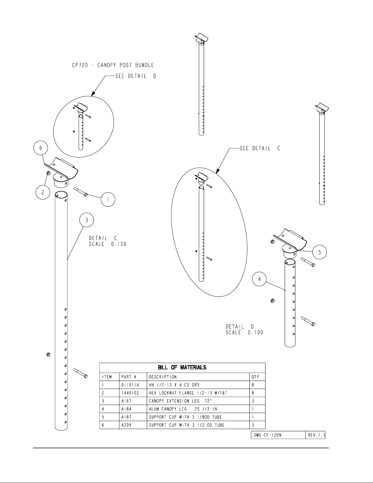
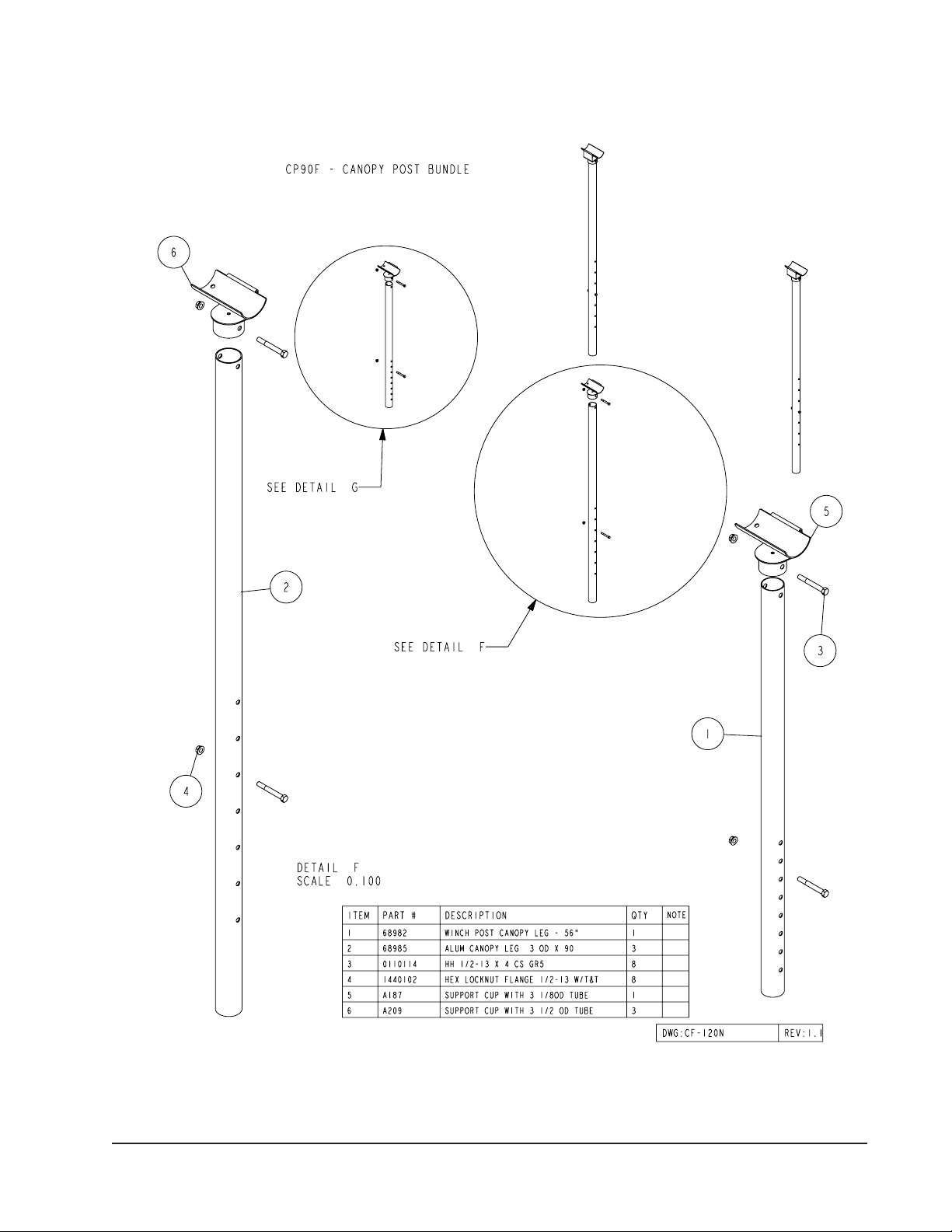
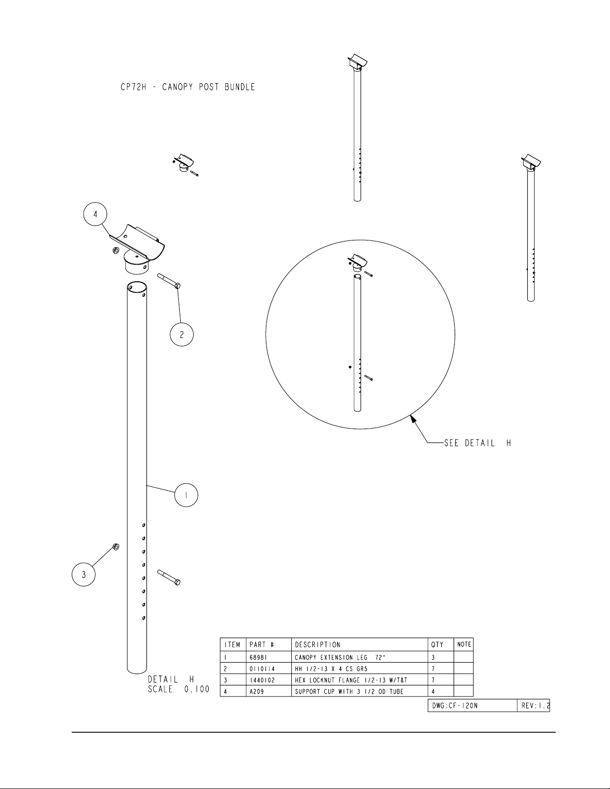
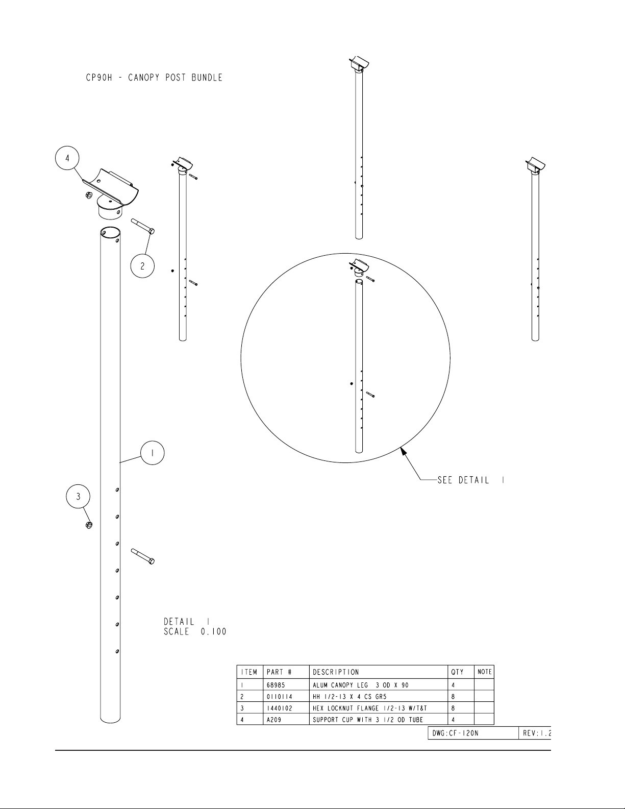
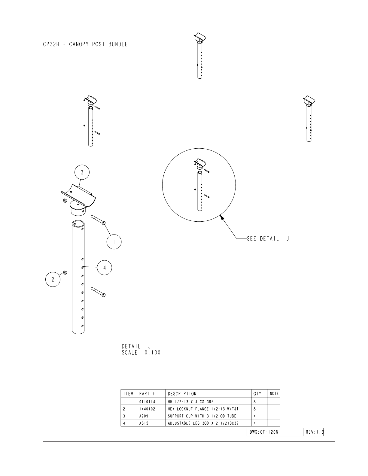
The canopy post assembly and installation instructions are supplied with the canopy post bundles and are located in the
support cup box. Use these instructions to attach the canopy posts to your hoist.
The following canopy post bundles are required to fit the following hoist.
Once the canpoy posts have been installed on your hoist continue to attach the canopy frame and vinyl as
follows.
Hoist Model Canopy Post Required Consists of Bundles
SSV30120 CP72D 68318, 68324
SSV40120 CP72D 68318, 68324
SSPV30120 CP72D 68318, 68324
SSPV40120 CP72D 68318, 68324
SSV30120DW CP30D 68318, 68325
SSV40120DW CP30D 68318, 68325
SSPV30120DW CP30D 68318, 68325
SSPV40120DW CP30D 68318, 68325
SSV40120HYD CP72K 68317, 68331
SSV50120 CP72M 68318, 68330
CP90F 68318, 68327
SSV50120DW CP32M 68318, 68329
SSV60120HYD CP72H 68317, 68332
CP90H 68317, 67567
SSV60120HYD DW CP32H 68317, 67320
SSV45120 (Steel Hoist) CP42G 68320, 68328
Midwest Industries, Inc. Ida Grove, IA 51445 800.859.3028 www.shorestation.com 0003526
Page 6 REV A 4/12/06
Midwest Industries, Inc. Ida Grove, IA 51445 800.859.3028 www.shorestation.com 0003526
Page 7 REV A 4/12/06

Midwest Industries, Inc. Ida Grove, IA 51445 800.859.3028 www.shorestation.com 0003526
Page 8 REV A 4/12/06
Midwest Industries, Inc. Ida Grove, IA 51445 800.859.3028 www.shorestation.com 0003526
Page 9 REV A 4/12/06
Midwest Industries, Inc. Ida Grove, IA 51445 800.859.3028 www.shorestation.com 0003526
Page 10 REV A 4/12/06
Midwest Industries, Inc. Ida Grove, IA 51445 800.859.3028 www.shorestation.com 0003526
Page 11 REV A 4/12/06
Midwest Industries, Inc. Ida Grove, IA 51445 800.859.3028 www.shorestation.com 0003526
Page 12 REV A 4/12/06
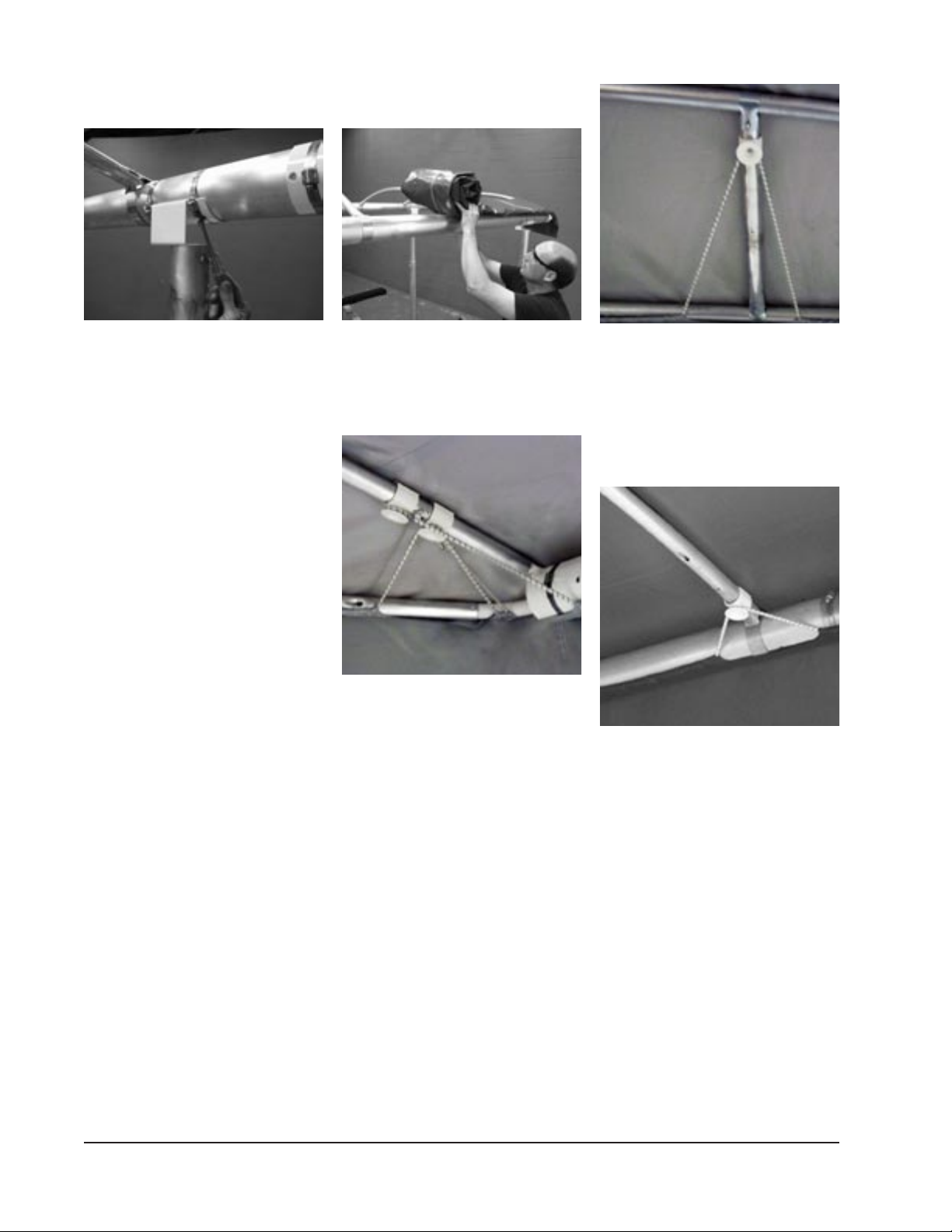
ATTACHING THE CANOPY FRAME
TO THE CANOPY POSTS
Determine the end of the hoist that your
boat will enter the hoist. This is the same
end that the motor stop will be mounted
on. Your boat will then be positioned
on the hoist so that more boat will be
extending forward of the hoist upright
post than what will be extended to the
rear. This is important because you will
want to position the canopy side frames
so that the longer section of side frame
extends to the front as well. This allows
the splice in the side frame to be posi-
tioned more in the center of the support
cups resulting in more strength.
Once the canopy is properly positioned,
raise the canopy frame up and place it
so the side frame tubes are resting in
the support cups on top of the canopy
posts. Position the canopy frame to
the proper position to best protect
your boat by sliding it either forward or
backward in the support cups. Also the
framework should be checked again
for being square. It is possible that this
may have changed in the process of
raising it into position. When the desired
position is achieved secure it to the
support cups by placing the large
stainless steel adjustable hose clamps
around the support cup and the canopy
side frame. Two hose clamps must
be placed on each end of each sup-
port cup. Place the hose clamps so
that the tightening mechanism of the
clamp is located on the inside portion
of the canopy side frame tube. Tighten.
The tightening mechanism is to be lo-
cated in this position so that it doesn’t
interfere with the cover when it is
installed.
NOTE: The CF30-120 is shipped stan-
dard with the HA0007 Brace Bundle.
The assembly instructions are included
with the brace bundles. These brace
bundles must be installed before the
vinyl is placed on the frame.
INSTALLING THE VINYL COVER TO
THE FRAME
Remove the vinyl cover from the box.
Unroll the vinyl cover down the side
frame as shown. When completely
unrolled, unfold the cover across the
canopy bows and pull down over the
framework.
The bungee cords are manufactured
to the correct length before they are
installed in the cover at the factory.
The installation process is as follows:
Stretch and attach the end loops on the
side frame bungee cords over the rim
of the plastic canopy cord spool hook
attached at the 10 ½” mark.
Stretch and attach the end loops on the
bungee in the end of the canopy to the
canopy cord spool hook positioned at
the 7 ½” mark in a similar manner.
Pull the end bungee cord from the next
slot in the end strap back up and over
the same canopy cord spool hook as
shown. Repeat on the other side of the
canopy.
Hook the center bungee up over the
canopy cord spool hook located at the
top of the 19” canopy spacer tube. Then
hook over the canopy cord spool hooks
at the top of the 16” spacer tubes.
Repeat this procedure on the other end
of the cover making sure the cover is
centered the same on each end.
Starting at the middle of the side frames
front to rear, pull the bungee cord on
the sides of the canopy cover over
the top side of the canopy cord spool
hooks. Alternate from side to side of
the canopy so the cover stays centered
on the frame. Continue until they are all
attached.
Once the bungee has been looped over
all of the canopy cord spool hooks,
check each one for adequate tension.
The bungee can be pulled through the
sewn in pocket so that the tension of
the cord over each spool hook can be
made even the full length and width of
the cover.
Check for tension again. If bungee ap-
pears tight, assembly is complete.

Midwest Industries, Inc. Ida Grove, IA 51445 800.859.3028 www.shorestation.com 0003526
Page 13 REV A 4/12/06
CANOPY COVER (VINYL)
MAINTENANCE
This canopy contains a mildew retar-
dant. Please follow these recommen-
dations to insure that this agent is not
destroyed and that the vinyl will not be
damaged.
1. Ordinary oil and dirt can be
removed with soapy water such as
laundry detergent. Apply with a mop,
sponge, brush or cloth followed by
a clear-water rinse. Stubborn spots
can be removed by using rubbing
(Isopropyl) alcohol in a well-venti-
lated area, away from open flames.
DO NOT USE gasoline, kerosene,
methyl ethyl Keytone (MEK) or
other solvents or bleaches.
2. Remove canopy when hoist is in
storage. Make sure canopy is dry
before folding and store in a warm,
dry location.
WARRANTY
Refer to your ShoreStation Owner’s
Packet for warranty information.
CANOPY END HOOD ADJUSTMENT
Your new canopy frame has adjustable
end hood brackets which allow the
frame to be adjusted a total of 1-1/2”
shorter or 1-1/2” longer from its normal
shipped position. This allows you to ad-
just your frame to fit the cover for length
should it need adjusting. The following
instructions will assist you in adjusting
the frame length.
1. Loosen the nuts on the adjust-
ing bolts located in the end of
the sideframe tube weldments.
Doing so will shorten the overall
length of the frame.
2. The frame can be lengthened to fit
the cover by tightening the nuts on
the bolts in the side frame tube
stop weldments just loosened in
Step 1.
Turn clockwise. As the nut is
threaded onto the bolt it will pull
the end hood out of the side
frame thus increasing the length
of the canopy framework.
Continue to lengthen the
frame until it is the right
length to fit the cover.
3. Once the proper length for the
frame has been achieved, stop
turning the nut.
Adjustment is complete.
If the bungee feel like they need to be
tighter, they can be tightened by simply
wrapping an additional wrap of the bun-
gee cord around one of the canopy cord
spool hooks. It may be tightened more
by repeating this process on as many
canopy cord spool hooks as needed.

Midwest Industries, Inc. Ida Grove, IA 51445 800.859.3028 www.shorestation.com 0003526
Page 14 REV A 4/12/06
Bundle Number Description Quantity
69092 Side Frame Tube Bundle - F24A 1
63748 Hoop Bundle - F241 1
69094 Hdwe Box - Canopy Frame 24/26-120 1
HA0039 Canopy Attach Hdwe 22/24/26-108/ 1
CF24-120N
Bundle Number Description Quantity
69093 Side Frame Tube Bundle - F261 1
62674 Hoop Bundle - F261 1
69094 Hdwe Box - Canopy Frame 24/26-120 1
HA0039 Canopy Attach Hdwe 22/24/26-108/ 1
68321 Canopy Brace Tube - Alum Bundle 1
68345 Brace Box CF26 - CF30 1
CF26-120N
Bundle Number Description Quantity
69095 Side Frame Tube Bundle - F30A 1
67166 Hoop Bundle - F301 1
69096 Hdwe Box - Canopy Frame 30-120 & 30-132 1
HA0042 Canopy Attach Hdwe 30-120/132N 1
68321 Canopy Brace Tube - Aluminum Bundle 1
68345 Brace Box CF26 - CF30 1
CF30-120N
Hoist Model Canopy Post Required Consists of Bundles
SSV30108 CP72D 68318, 68324
SSV40108 CP72D 68318, 68324
SSPV30108 CP72D 68319, 68324
SSPV40108 CP72D 68319, 68324
SSV30108DW CP30D 68318, 68325
SSV40108DW CP30D 68318, 68325
SSV50108 CP90F 68318, 68327
SS36110 (Steel Hoist) CP57G 68319, 68326
This manual suits for next models
2
Table of contents
Popular Tent manuals by other brands

ClearSpan
ClearSpan Beef Master 108440W manual

Big Agnes
Big Agnes Mine Mountain Series String Ridge 2 Setup instructions

Outsunny
Outsunny 84C-223 Assembly & instruction manual

Clarke
Clarke CIG1432 Assembly instructions

Kampa
Kampa Brean 4 Classic AIR Instructions & care manual

Belnick
Belnick JJ-GZ88-GG Assembly instructions


