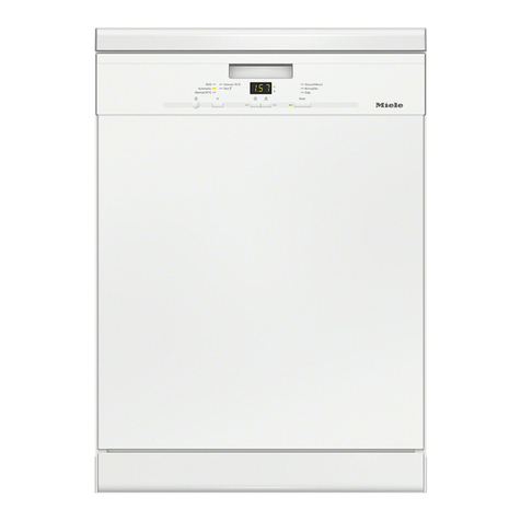
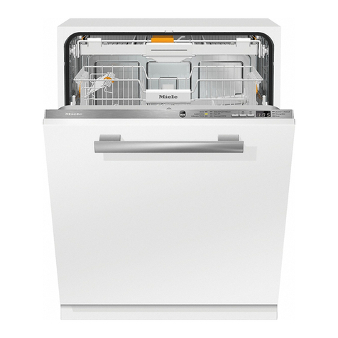
Miele G 1000 Manual

Technical Information
G1000 / G2000 Dishwashers
TECHNICAL INFORMATION
G1000 / G2000 Dishwashers
1

Technical Information
2
G1000 / G2000 Dishwashers
G1000 / G2000 Dishwasher - Table of Contents
WARNINGS AND SAFETY INFORMATION......................................................................10
1.0 CONSTRUCTION AND DESIGN...............................................................................11
1.1 Appliance Overview................................................................................................................................................11
1.1.1 Appliance Overview – Typical Integrated Model........................................................................................11
1.1.2 Appliance Overview – Typical Fully Integrated Model...............................................................................12
1.2 Controls Overview...................................................................................................................................................13
1.3 Types of Dishwashers..............................................................................................................................................14
1.3.1 Pre-Finished .................................................................................................................................................14
1.3.2 Integrated......................................................................................................................................................14
1.3.3 Fully Integrated ............................................................................................................................................14
1.4 Technical Data.........................................................................................................................................................15
1.4.1 Electrical Information...................................................................................................................................15
1.4.2 Plumbing Connections..................................................................................................................................16
1.4.2.1 Intake Connection..........................................................................................................................16
1.4.2.2 Drain Connection ..........................................................................................................................16
1.4.3 Dimensions...................................................................................................................................................16
1.5 Data Tag ..................................................................................................................................................................17
1.5.1 Data Tag - Location......................................................................................................................................18
1.5.2 Data Tag – Information................................................................................................................................18
1.6 Model Numbering....................................................................................................................................................18
1.6.1 Mode Numbering – Overview of USA Model Numbers..............................................................................19
1.7 Door Springs / Weights – Specifications.................................................................................................................20
1.8 Layout of Components (Typical).............................................................................................................................21
2.0 INSTALLATION .........................................................................................................22
3.0 COMMISSION AND OPERATION .............................................................................23
3.1 Door Handle / Lock – Prefinished & Integrated Models.........................................................................................23
3.2 Child Safety Lock....................................................................................................................................................23
3.3 Water Softener.........................................................................................................................................................24
3.3.1 Water Softener Salt – General Information..................................................................................................24
3.3.2 Water Softener Salt – Adding.......................................................................................................................24
3.4 General Operation....................................................................................................................................................26
3.4.1 Novotronic Controls.....................................................................................................................................26
3.4.2 Touchtronic & Navitronic Controls..............................................................................................................26
3.4.3 Fully Integrated (Incognito) (Vi) Controls...................................................................................................27
4.0 DESCRIPTION OF FUNCTION..................................................................................29
4.1 Cabinet Construction...............................................................................................................................................29
4.2 Water Intake ............................................................................................................................................................30
4.2.1 WaterProof System (WPS)...........................................................................................................................30
4.2.3 Water Inlet Mixer.........................................................................................................................................32
4.2.4 Water Inlet Mixer Without EGS...................................................................................................................35
4.2.5 Water Inlet Mixer wth EGS..........................................................................................................................36
4.2.6 Water Inlet Mixer during Reactivation.........................................................................................................37
4.2.7 Flow Meter B3/4, Water Intake Quantity.....................................................................................................38

Technical Information
G1000 / G2000 Dishwashers
G1000 / G2000 Dishwashers - Table of Contents (Continued)
4.2.8 Sensor Softener............................................................................................................................................38
4.2.9 Electronically Controlled Water Hardness (EGS).......................................................................................39
4.2.10 Intelligent Tab Function ..............................................................................................................................39
4.3 Water Circulation & Heating...................................................................................................................................41
4.3.1 Circulation Pump..........................................................................................................................................42
4.3.2 Circulation Pump - Speed Sensor and Load Sensing ...................................................................................43
4.3.3 Heating.........................................................................................................................................................45
4.3.4 NTC Temperature Sensor, R30....................................................................................................................45
4.3.5 Heater Pressure Switch, B1/13.....................................................................................................................47
4.3.6 Turbidity Sensor (ECO Sensor III, Auto-sensor), B3/10..............................................................................48
4.3.7 Spray Arm Sensing.......................................................................................................................................50
4.3.8 Filter Combination with Micro Fine Filter...................................................................................................51
4.4 Dispensing...............................................................................................................................................................52
4.4.1 Combination Dispenser ................................................................................................................................52
4.5 Drain System ...........................................................................................................................................................53
4.5.1 Drain Pump ..................................................................................................................................................53
4.6 Drying......................................................................................................................................................................54
4.6.1 Circulation Turbothermic Drying (active): UTT Version 1 .........................................................................54
4.6.2 Circulation Turbothermic Drying (active): UTT Version 2 .........................................................................56
4.6.3 Fan................................................................................................................................................................57
5.0 SERVICE AND MAINTENANCE................................................................................58
5.1 Housing....................................................................................................................................................................58
5.1.1 Side Panel – Removal..................................................................................................................................59
5.1.2 Drip Pan – Removal ....................................................................................................................................59
5.2 Door.........................................................................................................................................................................61
5.2.1 Front Panel (GDU / Custom) – Removal ....................................................................................................61
5.2.2 Door Tension – Adjustment ........................................................................................................................62
5.2.3 Outer Door Panel – Removal.......................................................................................................................64
5.2.4 Fascia Panel Removal..................................................................................................................................65
5.2.5 Door Hinge - Removal ................................................................................................................................65
5.2.6 Combination Dispenser Unit - Removal......................................................................................................67
5.2.7 Cable Holder - Removal..............................................................................................................................68
5.2.8 Bottom Door Seal - Removal ......................................................................................................................68
5.2.9 Locking Plate - Adjustment.........................................................................................................................69
5.2.10 Door Lock – Removal (Integrate Models)...................................................................................................70
5.2.11 Door Switch – Replacement (Integrated models)........................................................................................71
5.2.12 Fully Integrated (VI) Lock with Door Contact Switch Removal.................................................................72
5.2.13 Door lock emergency release – Activate (Fully Integrated)........................................................................72
5.3 Inner Cabinet ...........................................................................................................................................................73
5.3.1 Door Seal - Replacement.............................................................................................................................73
5.3.2 Toe Kick (Plinth Removal) .........................................................................................................................74
5.3.3 Cover Plate - Removal.................................................................................................................................75
5.3.4 Connecting Strip (Lower Support) – Removal............................................................................................76
5.3.5 Multi-Plinth Removal (Door Tension Spring Housing) ..............................................................................77
5.3.6 Steam Condenser Removal..........................................................................................................................78
5.3.7 Fan Removal................................................................................................................................................78
5.3.8 Basket Runners - Removal..........................................................................................................................79
5.3.9 Water Level Check......................................................................................................................................80
5.4.1 WaterProof System (WPS) Restrictor – Replacement ................................................................................82
5.4.2 WaterProof System (WPS) - Removal ........................................................................................................83
3
Technical Information
4
G1000 / G2000 Dishwashers
G1000 / G2000 Dishwashers - Table of Contents (Continued)
5.4.3 Flowmeter (circuit board) – Removal .........................................................................................................84
5.4.4 Top Spray Arm Removal.............................................................................................................................84
5.4.5 Middle Spray Arm Removal .......................................................................................................................84
5.4.6 Bottom Spray Arm Removal.......................................................................................................................85
5.4.7 Feed Pipe with Turbidity Sensor – Top Spray Arm, Removal....................................................................85
5.4.8 Feed Pipe – Middle Spray Arm, Removal...................................................................................................85
5.4.9 Spray Arm Sensor Removal........................................................................................................................85
5.4.10 Water Inlet Mixer with Resin Chamber – Removal....................................................................................86
5.4.11 EGS Valve Solenoid - Removal..................................................................................................................88
5.4.12 Reactivation Valve – Removal....................................................................................................................88
5.4.13 Salt Container - Removal ............................................................................................................................89
5.4.14 Circulation Pump - Removal.......................................................................................................................89
5.4.15 Circulation Pump - Service .........................................................................................................................91
5.4.15.1 Pump Cap Removal / Heater Element – Access .......................................................................92
5.4.15.2 Slide Shutter Removal ..............................................................................................................92
5.4.15.3 Drive Removal...........................................................................................................................93
5.4.15.4 Pump Impeller Removal ...........................................................................................................95
5.4.15.5 Pump Housing Removal ...........................................................................................................95
5.4.15.6 Capacitor Removal....................................................................................................................95
5.4.15.7 Heater Pressure Switch Removal ..............................................................................................95
5.4.15.8 Speed Sensor Removal..............................................................................................................95
5.4.16 Drain Pump Removal .................................................................................................................................96
5.4.17 Float Switch Removal................................................................................................................................96
5.4.18 Sump Removal ...........................................................................................................................................97
5.4.19 NTC Temperature Sensor Removal ...........................................................................................................98
5.4.20 Filter Combination Dismantling.................................................................................................................99
5.4.21 Filter Combination Assembly (New Micro Fine Filter and Handle)........................................................100
5.4.22 Filter Combination Assembly (with Locking Piece)................................................................................101
5.5 Electronic Unit.......................................................................................................................................................103
5.5.1 Mains Switch Removal (Integrated).........................................................................................................104
5.5.2 Electronic Unit Holder Removal..............................................................................................................105
5.5.3 Electronic Unit Removal (Integrated) ......................................................................................................105
6.0 FAULT DIAGNOSIS .................................................................................................106
6.1 Diagnostic Modes – Overview .............................................................................................................................106
6.1.1 Water Hardness Setting – Checking and Programming ...............................................................................107
6.2 Advanta Series.......................................................................................................................................................107
6.2.1 Advanta Series - G2020................................................................................................................................107
6.2.1.1 G2020 - Programming Mode....................................................................................................107
6.2.1.2 G2020 - Service Mode ..............................................................................................................112
6.2.1.3 G2020 Component Test – Information .....................................................................................115
6.2.2 Advanta Series – G2170...............................................................................................................................117
6.2.2.1 G2170 - Programming Mode ....................................................................................................117
6.2.2.2 G2170 - Service Mode ..............................................................................................................124
6.2.2.3 G2170 Component Test – Information .....................................................................................127
6.3 Inspira Series .........................................................................................................................................................129
6.3.1 Inspira Series - G2140 & G2150..................................................................................................................129
6.3.1.1 G2140 / G2150 - Programming Mode ......................................................................................129
6.3.1.2 G2140 / G2150 Service Mode...................................................................................................134
6.3.1.3 G2140 / G2150 Component Test - Information........................................................................137

Technical Information
G1000 / G2000 Dishwashers
G1000 / G2000 Dishwashers - Table of Contents (Continued)
6.3.2 Inspira Series - G1180 & G2180.................................................................................................................139
6.3.2.1 G1180 / G2180 - Programming Mode ......................................................................................139
6.3.2.2 G1180 / G2180 - Service Mode ................................................................................................146
6.3.2.3 G1180 / G2180 – Component Test............................................................................................149
6.4 Optima Series .......................................................................................................................................................151
6.4.1 Optima Series – G2420 & G2430.................................................................................................................151
6.4.1.1 G2420 / G2430 – Programming Mode.......................................................................................151
6.4.1.2 G2420 / G2430 - Service Mode Summary.................................................................................157
6.4.1.3 G2420 / G2430 Component Test ...............................................................................................160
6.4.2 Optima Series – G1470 & G2470...............................................................................................................162
6.4.2.1 G1470 / G2470 Programming Mode..........................................................................................162
6.4.2.2 G1470 / G2470 – Service Mode................................................................................................168
6.4.2.3 G1470 / G2470 Component Test ...............................................................................................170
6.5 Excella Series........................................................................................................................................................172
6.5.1 Excella Series – G2630................................................................................................................................172
6.5.1.1 G2630 Programming Mode........................................................................................................172
6.5.1.2 G2630 – Service Mode..............................................................................................................178
6.5.1.3 G2630 Component Test..............................................................................................................180
6.5.2 Excella Series – G2670 ................................................................................................................................183
6.5.2.1 G2670 Programming Mode........................................................................................................183
6.5.2.2 G2670 – Service Mode..............................................................................................................187
6.5.2.3 G2670 Component Test..............................................................................................................189
6.6 LaPerla - G2830....................................................................................................................................................192
6.6.1 G2830 - Program Mode..............................................................................................................................192
6.6.2 G2830 – Service Mode...............................................................................................................................197
6.6.3 G2830 Component Test..............................................................................................................................199
6.7 Fault Code Summary............................................................................................................................................203
6.8 Fault Repair Summary..........................................................................................................................................204
6.8.1 No Power - Main Switch Is On ..................................................................................................................204
6.8.2 Display shows “Close Salt Reservoir Cap”................................................................................................204
6.8.3 Drain Pump Switches On and Off at Short Intervals..................................................................................204
6.8.4 Inlet / Drain LED Flashes and Lights up Alternately (Fully Integrated) ..................................................205
6.8.5 Dishwasher Program Can Be Selected But Not Started.............................................................................205
6.8.6 Dishwashing program interrupted, no fault indication...............................................................................205
6.8.7 Door does not close correctly.....................................................................................................................206
6.8.8 Condensation forms on adjacent cabinets...................................................................................................206
6.8.9 Noises during drying cycle.........................................................................................................................207
6.8.10 Foreign object in drain system....................................................................................................................207
6.8.11 Poor Drying Results....................................................................................................................................208
6.8.12 No Drying Or Drying Too Slow.................................................................................................................208
6.8.13 Water Present In Appliance And Is Not Being Drained Off.......................................................................210
6.8.14 Inlet/Drain LED Flashes During Water Intake, Dishwasher ends selected program. (F12, F13 or F19)....211
6.8.15 Wash Program Is Interrupted And Drain Pump Is Operated.......................................................................214
6.8.16 The program is not interrupted, but faults are logged into the fault memory..............................................220
5

Technical Information
6
G1000 / G2000 Dishwashers
G1000 / G2000 Dishwashers - List of Figures
Figure 1-1: Appliance Overview (Typical Integrated Unit)............................................. 11
Figure 1-2: Appliance Overview (Typical Fully Integrated (Vi) Unit) ............................. 12
Figure 1-3: Pre-Finished Dishwasher............................................................................ 14
Figure 1-4: Integrated Dishwasher................................................................................ 14
Figure 1-5: Fully Integrated (Incognito) (Vi) Dishwasher............................................... 15
Figure 1-6: Dimensions ................................................................................................. 17
Figure 1-7: Data Tag Location ...................................................................................... 18
Figure 1-8: Data Tag Information .................................................................................. 18
Figure 1-9: Model Numbering ....................................................................................... 19
Figure 1-10: Layout of Components................................................................................ 21
Figure 2-1: Installation Manual (Typical) ....................................................................... 22
Figure 3-1: Door Handle Release ................................................................................. 23
Figure 3-2: Child Safety Lock........................................................................................ 23
Figure 3-3: Salt Container Release............................................................................... 25
Figure 3-4: Filling the Salt Using the Built In Funnel..................................................... 25
Figure 3-5: Display (Main Menu)................................................................................... 26
Figure 3-6: Display (With Selected Program)................................................................ 26
Figure 3-7: Display (With Selected Options) ................................................................. 27
Figure 3-8: Display (Main Menu)................................................................................... 27
Figure 3-9: Display (With Selected Program)................................................................ 27
Figure 3-10: Display (With Selected Options) ................................................................. 28
Figure 4-1: Inner Cabinet .............................................................................................. 29
Figure 4-2: WaterProof System Intake Valves .............................................................. 30
Figure 4-3: WaterProof System Flow Restrictor............................................................ 31
Figure 4-4: Water Inlet Mixer......................................................................................... 33
Figure 4-5: Inlet Mixer without EGS .............................................................................. 35
Figure 4-6: Inlet Mixer with EGS ................................................................................... 36
Figure 4-7: Inlet Mixer during Reactivation ................................................................... 37
Figure 4-8: Water Intake and Circulation Paths ............................................................ 41
Figure 4-9: Circulation Pump – Water Paths................................................................. 42
Figure 4-10: Circulation Pump - Components................................................................. 44
Figure 4-11: Heater Pressure Switch Circuit................................................................... 47
Figure 4-12: Turbidity Sensor Circuit .............................................................................. 48
Figure 4-13: Turbidity Sensor.......................................................................................... 49
Figure 4-14: Spray Arm Sensor ...................................................................................... 50
Figure 4-15: Filter Combination in Sump ........................................................................ 51
Figure 4-16: Combination Dispenser .............................................................................. 52
Figure 4-17: Drying System UTT Version 1 .................................................................... 54
Figure 4-18: Drying System UTT Version 2 .................................................................... 56
Figure 5-1: Toe Kick (Plinth) Removal .......................................................................... 75
Figure 5-2: Door Tension Adjustment ........................................................................... 62
Figure 5-3: Side Panel Removal ................................................................................... 59

Technical Information
G1000 / G2000 Dishwashers
G1000 / G2000 Dishwashers - List of Figures (Continued)
Figure 5-4: Door Seal with Door.................................................................................... 70
Figure 5-5: Door Seal Installation.................................................................................. 74
Figure 5-6: Drip Pan Removal....................................................................................... 60
Figure 5-7: Integrated Door Panel Screw Locations ..................................................... 62
Figure 5-8: Outer Door Panel Removal......................................................................... 64
Figure 5-9: Opening the Hinge Bracket......................................................................... 66
Figure 5-10: Front Hinge Retaining Screw...................................................................... 67
Figure 5-11: Side Hinge Retaining Screw ....................................................................... 67
Figure 5-12: Side Hinge Retaining Screw ....................................................................... 67
Figure 5-13: Dispenser Removal .................................................................................... 68
Figure 5-14: Lower door seal holder ............................................................................... 69
Figure 5-15: Door Lock Removal .................................................................................... 71
Figure 5-16: Cover Plate Removal.................................................................................. 76
Figure 5-17: Connecting Strip Removal .......................................................................... 77
Figure 5-18: Retaining Clip ............................................................................................. 80
Figure 5-19: Water Level Reference ............................................................................... 81
Figure 5-20: Tilting the Flow Restrictor ........................................................................... 83
Figure 5-21: Removing the Flow Restrictor..................................................................... 83
Figure 5-22: Water Intake Mixer Assembly and Related Components ........................... 88
Figure 5-23: Circulation Pump and Related Components (Typical)................................ 91
Figure 6-3: Circuit test path for F11. ............................................................................ 210
Figure 6-4: F19 - Start rinse block water intake ........................................................... 212
Figure 6-5: F19 – Test routine...................................................................................... 213
Figure 6-6: Circuit test path for F24. ............................................................................ 216
Figure 6-7: Circuit test path for F-51 (initial state)........................................................ 217
Figure 6-8: Circuit test path for F-51 (testing state) ..................................................... 218
7

Technical Information
8
G1000 / G2000 Dishwashers
G1000 / G2000 Dishwashers - List of Tables
Table 1-1: Controls Overview..........................................................................................................13
Table 1-2: Overview of US Model Numbers....................................................................................19
Table 1-3: Door Spring Summary ...................................................................................................20
Table 1-4: Panel weights/tension springs in delivery condition.......................................................20
Table 1-5: Panel weights/tension springs in customer service version...........................................20
Table 4-1: NTC Sensor Resistance Values ....................................................................................46
Table 6-1: Diagnostic Mode Overview by Series / Model Number................................................106
Table 6-2: Water Hardness: Standard setting: 15 gr/gal (15 °d) ...................................................107
Table 6-3: G2020 Programming Mode Options (continued on Table 6-4) ....................................108
Table 6-4: G2020 Programming Mode Options (cont. from Table 6-3) (cont. on Table 6-5) ........109
Table 6.5: G2020 Programming Mode Options (cont. from Table 6-4) (cont. to Table 6-6). ........110
Table 6.6: G2020 Programming Mode Options (continued from Table 6-5) .................................111
Table 6-7: G2020 Service Mode Options (Continued on Table 6-8).............................................113
Table 6-8: G2020 Service Mode Options (continued from Table 6-7) ..........................................114
Table 6-9: G2170 Programming Mode Options (continued on Table 6-10) ..................................118
Table 6-10: G2170 Programming Mode Options (Cont. from Table 6-9) (Cont. on Table 6-11).....119
Table 6-11: G2170 Programming Mode Options (Cont. from Table 6-10) (Cont. on Table 6-12)...120
Table 6-12: G2170 Programming Mode Options (Cont. from Table 6-11) (Cont. on Table 6-13)...121
Table 6-13: G2170 Programming Mode Options (Cont. from Table 6-12) (Cont. on Table 6-14)...122
Table 6-14: G2170 Programming Mode Options (continued from Table 6-13)...............................123
Table 6-15: Service Mode (G2170) (Continued on Table 6-16)......................................................125
Table 6-16: Service Mode (G2170) (Continued from Table 6-15)...................................................126
Table 6-17: G2140 Program Mode Options (Continued on Table 6-18) .........................................130
Table 6-18: G2140 Program Mode Options (Cont. from Table 6-17) (Cont. on Table 6-19) ..........131
Table 6-19: G2140 Program Mode Options (Cont. from Table 6-18) (Cont. on Table 6-20) ..........132
Table 6-20: G2140 Program Mode Options (Continued from Table 6-19)......................................133
Table 6-21: G2140 Service Mode Options (Continued on Table 6-22)...........................................135
Table 6-22: G2140 Service Mode Options (Continued from Table 6-21)........................................136
Table 6-23: G1180 / G2180 Programming Mode Options (Continued on Table 6-24) ...................140
Table 6-24: G1180 / G2180 Programming Mode Options (Cont. from Table 6-23)
(Cont. on Table 6-25) .................................................................................................141
Table 6-25: G1180 / G2180 Programming Mode Options (Cont. from Table 6-24)
(Cont. on Table 6-26) .................................................................................................142
Table 6-27: G1180 / G2180 Programming Mode Options (Cont. from Table 6-26)
(Cont. on Table 6-28) .................................................................................................144
Table 6-28: G1180 / G2180 Programming Mode Options (Continued from Table 6-27) ................145
Table 6-29: G1180 / G2180 Service Mode (Continued on Table 6-30) ..........................................147
Table 6-30: G1180 / G2180 Service Mode (Continued from Table 6-29) .......................................148
Table 6-31: G2420 / G2430 Programming Mode Options (Continued on Table 6-32) ...................152
Table 6-32: G2420 / G2430 Programming Mode Options (Cont. from Table 6-31)
(Cont. on Table 6-33) .................................................................................................153
Table 6-33: G2420 / G2430 Programming Mode Options (Cont. from Table 6-32)
(Cont. on Table 6-34) .................................................................................................154

Technical Information
G1000 / G2000 Dishwashers
G1000 / G2000 Dishwashers - List of Tables (Continued)
Table 6-34: G2420 / G2430 Programming Mode Options (Cont. from Table 6-33)
(Cont. on Table 6-35) .................................................................................................155
Table 6-35: G2420 / G2430 Programming Mode Options (Continued from Table 6-34) ................156
Table 6-36: G2420 / G2430 Service Mode Options (Continued on Table 6-37) .............................158
Table 6-37: G2420 / G2430 Service Mode Options (Continued from Table 6-36)..........................159
Table 6-38: G1470 / G2470 Programming Mode Options (Continued on Table 6-39) ...................163
Table 6-39: G1470 / G2470 Programming Mode Options (Cont. from Table 6-38)
(Cont. on Table 6-40) .................................................................................................164
Table 6-40: G1470 / G2470 Programming Mode Options (Cont. from Table 6-39)
(Cont. on Table 6-41) .................................................................................................165
Table 6-41: G1470 / G2470 Programming Mode Options (Cont. from Table 6-40)
(Cont. on Table 6-42) .................................................................................................167
Table 6-42: G1470 / G2470 Programming Mode Options (Continued from Table 6-41) ................167
Table 6-43: G1470 / G2470 Service Mode Options ........................................................................169
Table 6-44: G2630 Programming Mode Options (Continued on Table 6-45) .................................173
Table 6-45: G2630 Programming Mode Options (Cont. from Table 6-44) (Cont. on Table 6-46)...174
Table 6-46: G2630 Programming Mode Options (Cont. from Table 6-45) (Cont. on Table 6-47)...175
Table 6-47: G2630 Programming Mode Options (Cont. From Table 6-46) (Cont. on Table 6-48) .176
Table 6-48: G2630 Programming Mode Options (Continued on Table 6-47) .................................177
Table 6-49: G2630 Service Mode Options......................................................................................179
Table 6-50: G2670 Programming Mode Options (Continued on Table 6-51) .................................184
Table 6-51: G2670 Program Mode Options (Cont. from Table 6-50) (Cont. on Table 6-52) ..........185
Table 6-52: G2670 Programming Mode Options (Continued from Table 6-51) ..............................186
Table 6-53: G2670 Service Mode Options......................................................................................188
Table 6-54: G2830 Programming Mode Options (Continued on Table 6-55). ................................193
Table 6-55: G2830 Programming Mode Options (Cont. from Table 6-54) (Cont. on Table 6-56)...194
Table 6-56: G2830 Programming Mode Options (Continued from Table 6-55). .............................195
Table 6-57: G2830 Service Mode Options......................................................................................198
Table 6-58: Fault Code Summary ...................................................................................................203
9

Technical Information
10
G1000 / G2000 Dishwashers
Warnings and Safety Information
Service and repair work should only be carried out by suitably qualified persons in
accordance with all appropriate local and national safety regulations.
Before any service work is started, the appliance must be disconnected from the
power supply.
If it is necessary to tip the machine when working on the lower areas, it may only be
tilted onto its back. On models with salt container in the sump, the following must be
performed:
Empty the water inlet mixer: Open the salt container cap briefly, reinstall the cap and
ensure it is firmly secured. Any remaining water should then be removed from the
cabinet.
Upon completion of any service procedures, a short wash program without load
should be run. This is to remove any salt residues that might be present and prevent
possible corrosion.
If the retaining nut to the salt container becomes loose during repair work, the salt
container can slip out of the connection to the water inlet mixer. Should this occur the
salt container must be dismantled. To avoid leaks and additional procedures ensure
the salt container is supported via the service opening.
Do not tilt the unit onto its right side, as this would cause water to run into the fan.
Many procedures will require the machine to be placed on its back. Care should be
taken to avoid damage to the water hoses and power cord.
For questions, concerns, clarifications or further assistance contact the Miele
Technical Support Center at 1-800-999-1360.

Technical Information
G1000 / G2000 Dishwashers
1.0 Construction and Design
1.1 Appliance Overview
1.1.1 Appliance Overview – Typical Integrated Model
1 Upper Spray Arm (Not Visible)
2 Cutlery Tray (Depending On Model)
3 Upper Basket
4 Middle Spray Arm
5 Air Inlet For Drying (Depending On Model)
6 Lower Spray Arm
7 Filter Combination
8 Data Plate
9 Child Safety Lock In The Door Handle (Not Visible)
10 Rinse Aid Reservoir
11 Dual Compartment Detergent Dispenser
Figure 1-1: Appliance Overview (Typical Integrated Unit)
11

Technical Information
12
G1000 / G2000 Dishwashers
1.1.2 Appliance Overview – Typical Fully Integrated Model
1 Upper Spray Arm (Not Visible)
2 Cutlery Tray (Depending On Model)
3 Upper Basket
4 Middle Spray Arm
5 Air Inlet For Drying (Depending On Model)
6 Lower Spray Arm
7 Filter Combination
8 Data Plate
9 Optical Interface
10 Rinse Aid Reservoir
11 Dual Compartment Detergent Dispenser
12 Salt Container
Figure 1-2: Appliance Overview (Typical Fully Integrated (Vi) Unit)

Technical Information
G1000 / G2000 Dishwashers
1.2 Controls Overview
Controls on Miele dishwashers are categorized into four (4) types:
Control Type Description
Novotronic Each Novotronic model dishwasher can be operated with a single
knob. Surface mounted design technology (SMD) allows Miele
Novotronic components to be extremely durable and reliable.
These controls are capable of performing hundreds of tasks, which
cannot be handled by mechanical components.
Touchtronic This series of Miele dishwashers is operated by pushing a single
button – no separate temperature or drying selections – just turn
the machine on, select a program and Miele does the rest. All
models include a diverse group of wash programs for multiple
cleaning needs. Models are designed to maximize cleaning results
and optimize water and energy conservation.
Incognito (Fully
Integrated) (Vi)
The Incognito (fully integrated) series dishwashers have the
program controls located on the top edge of the door; and are
accessed while the door is open. Neither seen nor heard, the Miele
Incognito Series OCI (Optical cycle Indicator) allows you to see the
progress of the dishwasher cycle by way of a red light, which is
steady or flashing depending on the status of the cycle.
Navitronic The Navitronic Touch Display consists of two electronic boards
located behind the control panel. The front program electronic
board contains pad sensors, which respond to finger contact. Three
touch pad sensors are present on each side of the display to
control the menu items displayed next to them (indicated by a small
arrow) within the display area. During operation the display will
show:
The program name
The current time of day
The program sequence
The approximate remaining time
Faults and messages
Table 1-1: Controls Overview
13

Technical Information
14
G1000 / G2000 Dishwashers
1.3 Types of Dishwashers
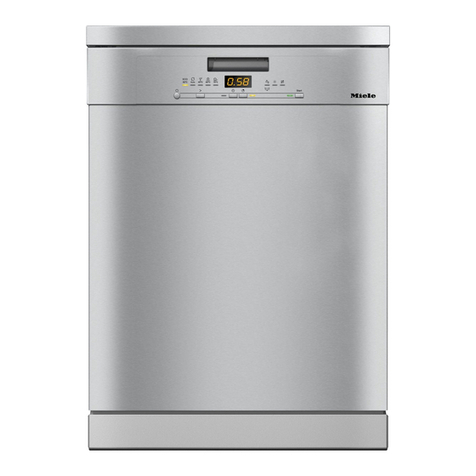
1.3.1 Pre-Finished
Figure 1-3: Pre-Finished Dishwasher
The pre-finished construction consist of a pre-assembled door panel and control
panel; making it an ideal replacement unit. Available in white, black or stainless steel.
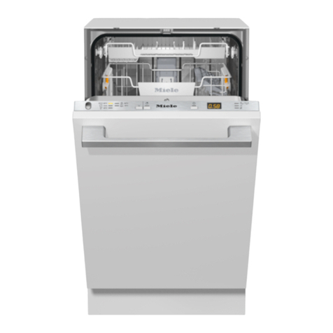
1.3.2 Integrated
Figure 1-4: Integrated Dishwasher
Integrated dishwashers ship with a separate control panel, and optional GDU (door)
panel. Every Integrated dishwasher ships with a bracket for installing a custom
cabinet panel. The use of separate components allows for a truly customized
installation.
1.3.3 Fully Integrated

Technical Information
G1000 / G2000 Dishwashers
Figure 1-5: Fully Integrated (Incognito) (Vi) Dishwasher
Fully Integrated Dishwashers are designed to blend into the surrounding cabinetry.
The operator controls are only available when door is opened. Each dishwasher is
shipped with a bracket for securing a custom cabinet panel. An optional Miele
stainless steel SCVi panel is also available.
1.4 Technical Data
1.4.1 Electrical Information
Power Requirements: 120 VAC, 60 Hz
Rated Load: 12.5 A / 1500 W (typical)
Circuit breaker: 15 AMPS
The appliance is equipped with a 4 ft power cord and molded NEMA 515 plug; for
connection to a NEMA 5-15R receptacle (120VAC, 15 Amp, 3 prong, grounded
outlet).
It is recommended that the power outlet for the appliance be installed on the wall
(within the cabinets), adjacent to under counter space where the appliance is
installed.
Ensure the cabinets contain no rough edges that could damage the power cord or
drain hose. If metal cabinets are used, ensure a rubber grommet is installed around
the opening.
Always exercise care when sliding the dishwasher in or out, to prevent damaging the
power cord and / or hoses.
Hard Wire Electrical Connection
Connections: L1 (Black) to L on terminal block, N (White) to N on terminal block,
15

Technical Information
16
G1000 / G2000 Dishwashers
GND To ground connector.
Hard wiring the dishwasher should only be done if required by electrical code.
Do not cut the plug off the power supply cord / plug and connect it directly to the
house wiring under any circumstances. This voids the warranty.
For hard wiring, the power cord must be removed from the appliance by
disconnecting the cord from the terminal box located at the lower left front of the
dishwasher, behind the Toekick and Service Panel. Pass the permanent power
supply cable through the strain relief and secure it directly to the terminal box.
THIS APPLIANCE MUST BE GROUNDED
1.4.2 Plumbing Connections
1.4.2.1 Intake Connection
The appliance is equipped with a five (5) foot long Double WaterProof System Intake
Hose; equipped with a ¾ inch female hose connection; for connection to a ¾ inch
male hose thread water supply valve.
1.4.2.2 Drain Connection
The appliance is equipped with a five (5) foot long Drain Hose for connection to a ¾
inch drain nipple.
1.4.3 Dimensions

Technical Information
G1000 / G2000 Dishwashers
Figure 1-6: Dimensions
For the latest product specifications, including product dimensions visit: Miele.com
1.5 Data Tag
17

Technical Information
18
G1000 / G2000 Dishwashers
1.5.1 Data Tag - Location
Figure 1-7: Data Tag Location
1.5.2 Data Tag – Information
Figure 1-8: Data Tag Information
1.6 Model Numbering

Technical Information
G1000 / G2000 Dishwashers
Figure 1-9: Model Numbering
1.6.1 Mode Numbering – Overview of USA Model Numbers
G2020
G2020SC
G2170Vi
Advanta Series G2170SCVi
-
Inspira Series G2140
Table 1-2: Overview of US Model Numbers
G2140SC
G2140i
G2150 G2180Vi
G2150SC G2180SCVi
G1180SCvi
Optima Series G2420SCi G2430SC
G2430SCi
G2470SCVi
G1470SCVi
Excella G2630SCi G2670SCi -
LaPeral G2830 - -
19

Technical Information
20
G1000 / G2000 Dishwashers
1.7 Door Springs / Weights – Specifications
Springs should always be installed in matching pairs
Model Color Tensile strength
(N)
Length (mm)
G1xxx, free-
standing, built-
under
Orange Approx. 230 150
G2xxx, built
under
Blue Approx. 290 157
G1xxx, (I) (VI) Uncolored Approx. 320 156
G2xxx, (I) (VI) Green Approx. 410 155
Table 1-3: Door Spring Summary
Door panel weights/tension springs – factory
Series
Control panel
type
Color Max. weight of
front panel (Kg)
G1xxx I Synthetic fiber Uncolored 10
G1xxx I Stainless steel Uncolored 9
G2xxx I Synthetic fiber Green 13
G2xxx I Stainless steel Green 11
Table 1-4: Panel weights/tension springs in delivery condition
Door panel weights/tension springs - service installed versions
Series
Control panel
type
Color Max. weight of
front panel (Kg)
G1xxx I Synthetic fiber Green 15
G1xxx I Stainless steel Green 14
G2xxx I Synthetic fiber - -
G2xxx I Stainless steel - -
Table 1-5: Panel weights/tension springs in customer service version
Other manuals for G 1000
8
This manual suits for next models
21
Table of contents
Other Miele Dishwasher manuals

Miele
Miele G 865 User manual

Miele
Miele G 4286 User manual

Miele
Miele WT 2679 i WPM User manual

Miele
Miele G 1162 SCVi User manual

Miele
Miele G 2630 SCi User manual

Miele
Miele Crystal G 5105 SC Parts list manual

Miele
Miele G 693-4 User manual

Miele
Miele G 6160 User manual

Miele
Miele Incognito G 643 SCVi User manual

Miele
Miele Diamond G 5915 SCi Parts list manual