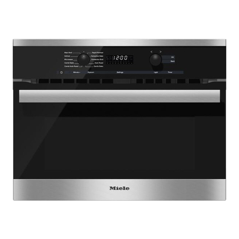
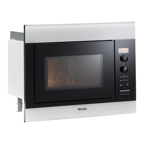
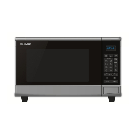
Miele M 6160 TC User manual

Descriptive Technical
Documentation
- Model-dependent -
DTD no. 24-6160
Model(s): M 6160 TC, M 6260 TC, M 6262 TC
01.10.2014, US_am This information should not be duplicated or passed on without Miele approval. All rights reserved.
Contents
General Information
A Warning and Safety Instructions
B Modification History
C Technical Data
D Layout of Electrical Components
Function Groups
001 Overview
2 Function ........................................... 001-1
2.1 FanRun-On .......................................... 001-1
2.2 Automatic Keep-Warm Function . . . . . . . . . . . . . . . . . . . . . . . . . . 001-1
2.3 Safety Feature with Door Display......................... 001-1
3 Fault Repair ........................................ 001-2
3.1 Turntable Cannot Be Deactivated . . . . . . . . . . . . . . . . . . . . . . . . . 001-2
3.2 Condensate Deposits on Furniture Fronts . . . . . . . . . . . . . . . . . . 001-2
3.3 Rust Stains in Stainless-Steel Cavity . . . . . . . . . . . . . . . . . . . . . . 001-3
3.4 Sparks When Using the Gourmet Plate . . . . . . . . . . . . . . . . . . . . 001-3
3.5 Time Not Displayed and Appliance Is Switched Off . . . . . . . . . . 001-4
3.6 Service Mode Cannot Be Accessed . . . . . . . . . . . . . . . . . . . . . . . 001-4
3.7 Operation Not Possible . . . . . . . . . . . . . . . . . . . . . . . . . . . . . . . . . 001-5
3.8 Maximum Time Selection of Only 15 Minutes Possible. . . . . . . . 001-5
3.9 “Door”IsDisplayed..................................... 001-6
3.10 Appliance Does Not Heat Up . . . . . . . . . . . . . . . . . . . . . . . . . . . . 001-6
3.11 Display Remains Blank . . . . . . . . . . . . . . . . . . . . . . . . . . . . . . . . . 001-7
4 Service............................................. 001-8
4.1 System Lock Activation/Deactivation . . . . . . . . . . . . . . . . . . . . . . 001-8
4.2 Programming Mode . . . . . . . . . . . . . . . . . . . . . . . . . . . . . . . . . . . . 001-9
4.3 ServiceMode......................................... 001-12
4.4 Removing the Microwave Oven from a Housing Unit . . . . . . . . . 001-14
4.5 CoverRemoval........................................ 001-15
4.6 Door Removal and Installation . . . . . . . . . . . . . . . . . . . . . . . . . . . 001-17
4.7 DoorAdjustment....................................... 001-18
4.8 Handle Replacement . . . . . . . . . . . . . . . . . . . . . . . . . . . . . . . . . . . 001-21
4.9 Turntable Motor (M22) Removal . . . . . . . . . . . . . . . . . . . . . . . . . . 001-26
4.10 Fascia Panel Removal . . . . . . . . . . . . . . . . . . . . . . . . . . . . . . . . . . 001-29
4.11 Selection Electronic Removal . . . . . . . . . . . . . . . . . . . . . . . . . . . . 001-31
4.12 Selector Switch Removal. . . . . . . . . . . . . . . . . . . . . . . . . . . . . . . . 001-33
4.13 Switch Knob Removal . . . . . . . . . . . . . . . . . . . . . . . . . . . . . . . . . . 001-34
4.14 Control Electronic (N1) Removal. . . . . . . . . . . . . . . . . . . . . . . . . . 001-35
Descriptive Technical Documentation
DTD no. 24-6160 1
01.10.2014, US_am This information should not be duplicated or passed on without Miele approval. All rights reserved.
4.15 Power Electronic Removal. . . . . . . . . . . . . . . . . . . . . . . . . . . . . . . 001-37
4.16 Door Lock Removal (Not US Models). . . . . . . . . . . . . . . . . . . . . . 001-37
4.17 Door Safety Switch (F6/6) Removal . . . . . . . . . . . . . . . . . . . . . . . 001-39
4.18 Interference Suppression Filter (Z1) Removal . . . . . . . . . . . . . . . 001-40
4.19 Fine-Wire Fuse (F8) Removal . . . . . . . . . . . . . . . . . . . . . . . . . . . . 001-41
4.20 Cooling Fan (M2) Removal . . . . . . . . . . . . . . . . . . . . . . . . . . . . . . 001-42
4.21 High-Voltage Capacitor (A4) Removal . . . . . . . . . . . . . . . . . . . . . 001-45
4.22 Magnetron (G2) Removal . . . . . . . . . . . . . . . . . . . . . . . . . . . . . . . 001-46
4.23 Transformer (T1) Removal. . . . . . . . . . . . . . . . . . . . . . . . . . . . . . . 001-47
4.24 Cavity Temperature Limiter (F1/1) Removal. . . . . . . . . . . . . . . . . 001-48
4.25 Magnetron Temperature Limiter (F1/2) Removal . . . . . . . . . . . . . 001-49
4.26 Lighting Assembly Removal . . . . . . . . . . . . . . . . . . . . . . . . . . . . . 001-50
4.27 Microwave Power Test . . . . . . . . . . . . . . . . . . . . . . . . . . . . . . . . . . 001-51
4.28 Transformer (T1) Primary Winding Test . . . . . . . . . . . . . . . . . . . . 001-51
4.29 Transformer (T1) High-Voltage Secondary Winding Test . . . . . . 001-52
4.30 Transformer (T1) Low-Voltage Secondary Winding (Heater
Filament Winding) Test . . . . . . . . . . . . . . . . . . . . . . . . . . . . . . . . . 001-53
4.31 High-Voltage Capacitor (A4) Functional Test . . . . . . . . . . . . . . . . 001-54
4.32 High-Voltage Capacitor (A4) Earth Leakage Test . . . . . . . . . . . . 001-55
4.33 Diode(V1)Test........................................ 001-56
4.34 Protective Diode (V6) Test . . . . . . . . . . . . . . . . . . . . . . . . . . . . . . . 001-57
4.35 Magnetron (G2) Heater Filament Test . . . . . . . . . . . . . . . . . . . . . 001-57
4.36 Magnetron (G2) Earth Leakage Test . . . . . . . . . . . . . . . . . . . . . . 001-58
Descriptive Technical Documentation
2 DTD no. 24-6160
This information should not be duplicated or passed on without Miele approval. All rights reserved. 01.10.2014, US_am

A Warning and Safety Instructions
1 General Information
Service and repair work should only be carried out by a suitably qualified
electrician (with specialist training, knowledge and experience, and recent related
work experience) in accordance with all appropriate local and national safety
regulations.
Servicing, modification, testing and maintenance of electrical appliances should
only be carried out in accordance with all appropriate legal requirements, accident
prevention regulations and valid standards.
All regulations of the appropriate utility supply companies and standards relating
to safety (not limited to electrical safety) are to be complied with.
Before starting any service work, the machine must be disconnected from power.
Even with the machine switched off, voltage may be applied to some
components.
A general visual check should always be carried out.
There may be a risk of injury due to sharp edges. Protective gloves should be
worn and the edge protection, mat. no. 05057680, should be used.
Descriptive Technical Documentation
DTD no. 24-6160 A-1
01.10.2014, US_am This information should not be duplicated or passed on without Miele approval. All rights reserved.

2 High Voltages
x
Danger!
Normally when the microwave oven is switched off, the built-in discharge
resistors in the high-voltage capacitors discharge the capacitors.
For safety reasons, it is important to ensure that the high-voltage
capacitors are discharged by always short-circuiting them before starting
any maintenance or repair work.
When the microwave oven is connected to power, the following components
have potentially lethal voltage applied to them:
•High-voltage transformer (T1)
•High-voltage capacitor (A4)
•Diode (V1)
•Magnetron (G2)
Descriptive Technical Documentation
A-2 DTD no. 24-6160
This information should not be duplicated or passed on without Miele approval. All rights reserved. 01.10.2014, US_am

3 Discharging the High-Voltage Capacitor
Note
Although the high-voltage capacitor contains an internal bleed resistor to
automatically discharge the capacitor, the following procedure must be
performed! Do not rely on a functioning resistor!
Unplug the appliance.
Remove the cover. See Cover Removal, 001 4.5.
Using an insulated-handled screwdriver, touch the blade from one terminal on the
capacitor to the other terminal on the capacitor. This may result in a rather
startling “pop!”
Using the same insulated-handled screwdriver, touch the blade from each
terminal on the capacitor to the frame (ground) of the appliance.
Descriptive Technical Documentation
DTD no. 24-6160 A-3
01.10.2014, US_am This information should not be duplicated or passed on without Miele approval. All rights reserved.
4 Microwave Energy
Microwave energy is created by the magnetron or another microwave generator.
x
Danger!
The body must not be subjected to any microwave energy under any
circumstances as this could result in serious internal injuries.
The following points must always be complied with:
•The magnetron or other microwave generator must be connected correctly.
•All input and output connections, waveguides, flanges and seals must be
sealed correctly.
•A microwave oven must never be operated without a microwave load.
•Never look into an open waveguide or antenna when the microwave oven is
on.
In order to ensure that no microwave energy can escape after any repair
work has been completed, the microwave oven must be thoroughly
checked for microwave leaks in accordance with all applicable local and
national regulations. (In Germany: VDE regulation 0700 and CEE
regulation 335 apply.)
Checks should be carried out using a suitable microwave leak detector (mat. no.
05595470). Particular care should be taken around the door and the casing
edges.
The maximum permissible value is 5mW/cm
2
(32.3mW per square inch),
measured at a distance of 5cm (2 inches) from the oven with a water load of
275cm
3
±15cm
3
(0.073 gallons ± 0.004 gallons).
Descriptive Technical Documentation
A-4 DTD no. 24-6160
This information should not be duplicated or passed on without Miele approval. All rights reserved. 01.10.2014, US_am
5 Touch Current Measurement
Note
On machines with a ground connection, touch current leakage measurements
should be carried out on all accessible conductive parts that are not connected
to ground.
Warning!
Touch current measurement should only be carried out after the ground
connection of the machine under test has been checked and found to be
satisfactory! Dangerous voltages may exist on defective machines as well as on
accessible conductive parts that are not connected to ground!
Note
Touch current measurement should be carried out on the following accessible
conductive parts:
•Stainless-steel door.
Descriptive Technical Documentation
DTD no. 24-6160 A-5
01.10.2014, US_am This information should not be duplicated or passed on without Miele approval. All rights reserved.
B Modification History
When? Who? What?
02.07.2014 Sabine Hötte Version 7
07.05.2014 Sabine Hötte Version 6
10.04.2014 Sabine Hötte Version 5
02.12.2013 Martina Aßmann,
Sabine Hötte
Version 4
16.10.2013 Sabine Hötte Version 3
12.06.2013 Sabine Hötte Version 2
15.05.2013 Sabine Hötte Version 1
Descriptive Technical Documentation
DTD no. 24-6160 B-1
01.10.2014, US_am This information should not be duplicated or passed on without Miele approval. All rights reserved.
C Technical Data
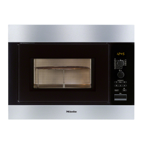
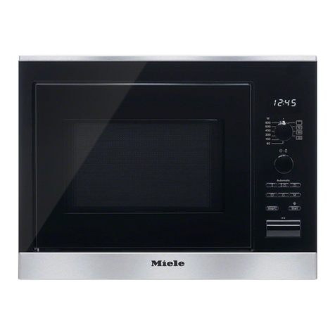
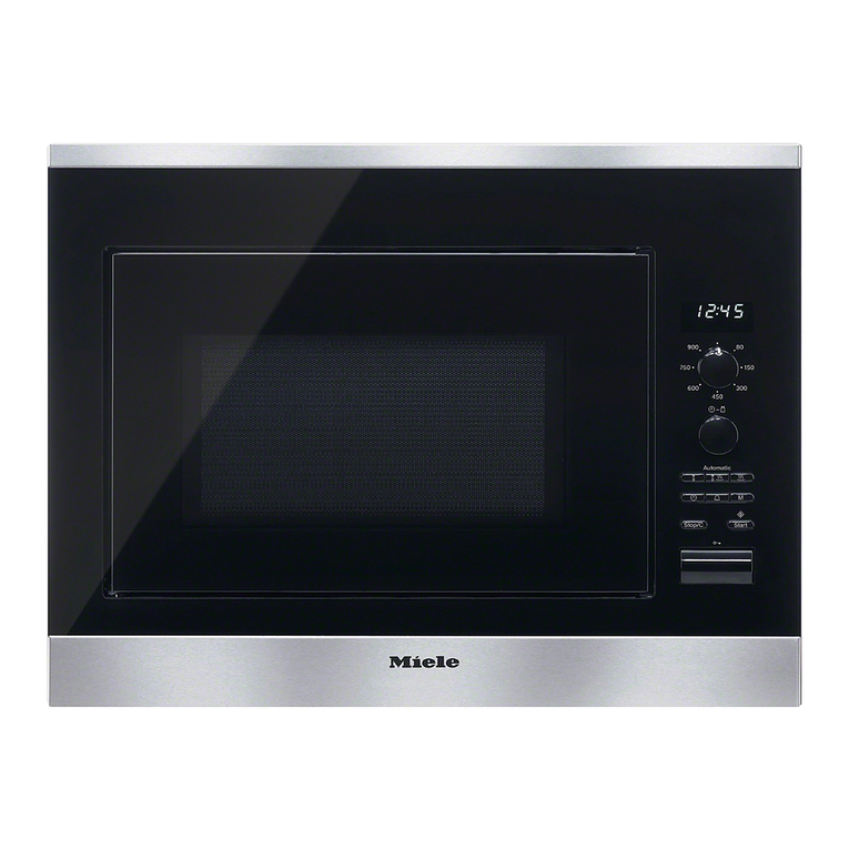
Fig. 1: M 6160 TC
Descriptive Technical Documentation
DTD no. 24-6160 C-1
01.10.2014, US_am This information should not be duplicated or passed on without Miele approval. All rights reserved.

Fig. 2: M 6260 TC
Model/Sales designation M 6160 TC M 6260 TC
Illustration See C Fig. 1. See C Fig. 2.
Construction type
Freestanding microwave oven - -
Built-in microwave oven X X
Design
PureLine - X
ContourLine X -
SideControl - -
TopControl X X
Display EasyControl X X
Fascia panel with symbols X X
Retractable knobs X X
Convenience features
Electronically controlled microwave power X X
Descriptive Technical Documentation
C-2 DTD no. 24-6160
This information should not be duplicated or passed on without Miele approval. All rights reserved. 01.10.2014, US_am

Model/Sales designation M 6160 TC M 6260 TC
Operating modes
Power levels 80W 80W
150W 150W
300W 300W
450W 450W
600W 600W
750W 750W
900W 900W
Keep-warm X X
Automatic programs 16 16
User convenience
Popcorn function X X
Time-of-day display X X
Minute minder X X
Automatic switch-off X X
QuickStart X X
Memory function X X
Door
Door hinge side
Bottom X X
Changeable - -
Oven interior
Volume 1.6 cu. ft. 1.6 cu. ft.
LED lighting X X
Height 8.3”8.3”
Turntable diameter 15.7”15.7”
Cleaning and care
Stainless-steel front with CleanSteel finish X X
Efficiency and sustainability
Night dimming X X
Safety
System lock X X
Safety switch X X
Safety lock / "Door" in display X X
Technical data
Niche dimensions
Width 22.0”- 22.4”22.0”- 22.4”
Height 17.6”- 17.8”17.6”- 17.8”
Depth 19.7”19.7”
Descriptive Technical Documentation
DTD no. 24-6160 C-3
01.10.2014, US_am This information should not be duplicated or passed on without Miele approval. All rights reserved.
Model/Sales designation M 6160 TC M 6260 TC
Oven dimensions
Width 23.4”23.4”
Height 17.8”17.8”
Depth 18.9”18.9”
Niche-independent venting X X
Total rated load 1.6kW 1.6kW
Voltage 120VAC 120VAC
Fuse rating 15A 15A
Power cord length 4' 4'
Standard accessories
Cover 1 1
Boiling rod 1 1
Broiling rack - -
Glass tray - -
Gourmet plate - -
Table 1: Technical Data
M 6160 TC M 6260 TC
Turntable motor (M22)
Voltage 120VAC 120VAC
Frequency 60Hz 60Hz
Cooling fan (M2)
Voltage 120VAC 120VAC
Frequency 60Hz 60Hz
Transformer (T1)
Voltage 120VAC 120VAC
Frequency 60Hz 60Hz
High-voltage capacitor (A4)
Capacitance 0.94µF 0.94µF
Voltage 2100VAC 2100VAC
Cavity temperature limiter (F1/1)
Cut-out temperature 302°F 257°F
Magnetron temperature limiter (F1/2)
Cut-out temperature 257°F 257°F
Fine-wire fuse (F8)
Fuse rating 20A 20A
Dimensions (Cx L) 0.2”x 0.8”0.2”x 0.8”
Table 2: Technical Data - Components
Descriptive Technical Documentation
C-4 DTD no. 24-6160
This information should not be duplicated or passed on without Miele approval. All rights reserved. 01.10.2014, US_am
D Layout of Electrical Components
M 6160 TC, M 6260 TC
Electrical components:
x
Layout 1
1 Cooling fan (M2)
2 20A fine-wire fuse (F8)
3 Interference suppression filter (Z1)
4 Cooling temperature limiter (not US models)
5 Cavity temperature limiter, 257°F (F1/1)
6 Diode (V1)
7 Protective diode (V6)
8 High-voltage capacitor (A4)
9 Transformer (T1)
10 Door safety switch (2F6/6)
11 Door safety switch (1F6/6)
12 Door safety switch (3F6/6)
Note: The illustration shows 3 door switches on the right side. This is for
European models. US models have 4 door switches, 2 per side.
13 Turntable motor (M22)
14 Selector switch
15 Cavity light (H3/2)
Descriptive Technical Documentation
DTD no. 24-6160 D-1
01.10.2014, US_am This information should not be duplicated or passed on without Miele approval. All rights reserved.

16 Selector switch
17 Selection electronic
18 Control electronic (N1)
19 Magnetron (G2)
20 Magnetron temperature limiter, 257°F (F1/2)
Descriptive Technical Documentation
D-2 DTD no. 24-6160
This information should not be duplicated or passed on without Miele approval. All rights reserved. 01.10.2014, US_am

Control electronic plug connections:
x
Layout 2
1 Function selector switch
2 Selection module
3 Time/weight selector switch
4 Top right door switch
5 Magnetron temperature limiter (F1/2), cooling fan (M2), bottom left
door switch
6 Transformer (T1), top left door switch, interference suppression
board (Z1)
7 Broil element (not US models)
8 Cavity light (H3/2)
9 Cavity temperature limiter (F1/1)
Descriptive Technical Documentation
DTD no. 24-6160 D-3
01.10.2014, US_am This information should not be duplicated or passed on without Miele approval. All rights reserved.
001 Overview
2 Function
2.1 Fan Run-On
With all cooking processes lasting longer than 3 minutes, the cooling fan is
switched on for 2 minutes at the end of cooking regardless of whether the door
has been opened or not. The fan, however, only operates when the door is
closed. If the door is opened during this time, the fan run-on time is reduced
accordingly.
2.2 Automatic Keep-Warm Function
If, at the end of a cooking process with at least 450W microwave power, the door
is not opened, then after 2 minutes the keep-warm function is activated and
continues for a maximum of 15 minutes with microwave power of 80W. This
function cannot be selected separately. The display shows H:H.
The automatic keep-warm function can be deactivated in the programming mode;
see Programming Mode, 001 4.2.
2.3 Safety Feature with Door Display
If the door has not been opened within 20 minutes before starting a cooking
process, the appliance cannot be started and door is displayed. This reduces the
risk that the appliance can be started with nothing in the oven.
The door warning can be deactivated in the programming mode; see
Programming Mode, 001 4.2.
Descriptive Technical Documentation
DTD no. 24-6160 001-1
01.10.2014, US_am This information should not be duplicated or passed on without Miele approval. All rights reserved.
3 Fault Repair
3.1 Turntable Cannot Be Deactivated
Cause
This is not a fault.
To ensure even cooking and even browning when broiling, the turntable cannot
be switched off.
Remedy
ANone.
x
Note
The turntable and cavity light are activated via the same relay.
3.2 Condensate Deposits on Furniture Fronts
Symptom
During long cooking cycles condensate deposits develop on neighboring kitchen
cabinetry.
Cause
Cooking power level too high.
Remedy
AReduce the power level.
Cause
Food being cooked not covered.
Remedy
ACover the food being cooked.
Descriptive Technical Documentation
001-2 DTD no. 24-6160
This information should not be duplicated or passed on without Miele approval. All rights reserved. 01.10.2014, US_am
3.3 Rust Stains in Stainless-Steel Cavity
Cause
Vinegar or cleaning agent containing chlorine has been used for cleaning.
Parts required
x
Quantity Mat. no. Designation
1 05050401 Ceramic cooktop cleaner
1 04565110 Neoblank stainless steel care agent
Remedy
ARemove rust stains with ceramic cooktop cleaner.
AProtect the surface with Neoblank stainless steel care agent.
x
Note
Advise the customer that vinegar or cleaning agents containing chlorine should
not be used for cleaning.
3.4 Sparks When Using the Gourmet Plate
Symptom
Over a long period the sparking can damage the gourmet plate and the oven
cavity.
Cause
The gourmet plate has been used on the oven rack.
Remedy
AAdvise the customer that the gourmet plate should not be used on the rack
but should be placed directly on the turntable.
Cause
The gourmet plate has less than 1”gap to the cavity walls.
Descriptive Technical Documentation
DTD no. 24-6160 001-3
01.10.2014, US_am This information should not be duplicated or passed on without Miele approval. All rights reserved.

Remedy
AAdvise the customer that the gourmet plate should be placed in position so
that the gap to the cavity walls is at least 1”. If the gourmet plate is too large, it
must not be used.
3.5 Time Not Displayed and Appliance Is Switched Off
Symptom
If the appliance is not used for 10 minutes, the time display is switched off. The
appliance is also switched off and must be switched on again before it can be
used.
Cause
The time-of-day display including operational readiness state is switched off.
Remedy
x
Note
If the time-of-day display including operational readiness state is switched on,
the service mode cannot be accessed; see Service Mode Cannot Be Accessed,
001 3.6.
ASwitch on the time-of-day display including operational readiness state; see
Programming Mode, 001 4.2.
3.6 Service Mode Cannot Be Accessed
Cause
The time-of-day display including operational readiness state is switched on.
The service mode can only be accessed if the time-of-day display including
operational readiness state is switched off.
Remedy
ASwitch off the time-of-day display including operational readiness state; see
Programming Mode, 001 4.2.
Descriptive Technical Documentation
001-4 DTD no. 24-6160
This information should not be duplicated or passed on without Miele approval. All rights reserved. 01.10.2014, US_am
Other manuals for M 6160 TC
3
This manual suits for next models
2
Table of contents
Other Miele Microwave Oven manuals

Miele
Miele M 6040 SC User manual

Miele
Miele M 6260 TC User manual

Miele
Miele H6300BM User manual

Miele
Miele TX2070 User manual

Miele
Miele H6800BM User manual

Miele
Miele H 4042 BM User manual

Miele
Miele MLT75 User guide

Miele
Miele M 8260 User manual

Miele
Miele M 625 EG User manual

Miele
Miele H4042BM User manual

Miele
Miele TX3587 User manual

Miele
Miele M 2240 SC User manual

Miele
Miele M 8260-2 User manual

Miele
Miele M 7244 TC User manual

Miele
Miele M 8261-1 User manual

Miele
Miele M 8161-2 User manual

Miele
Miele H 168 MB User manual

Miele
Miele M 637-45 ECR User manual

Miele
Miele M 625 EG User manual

Miele
Miele H4080BMSS Parts list manual