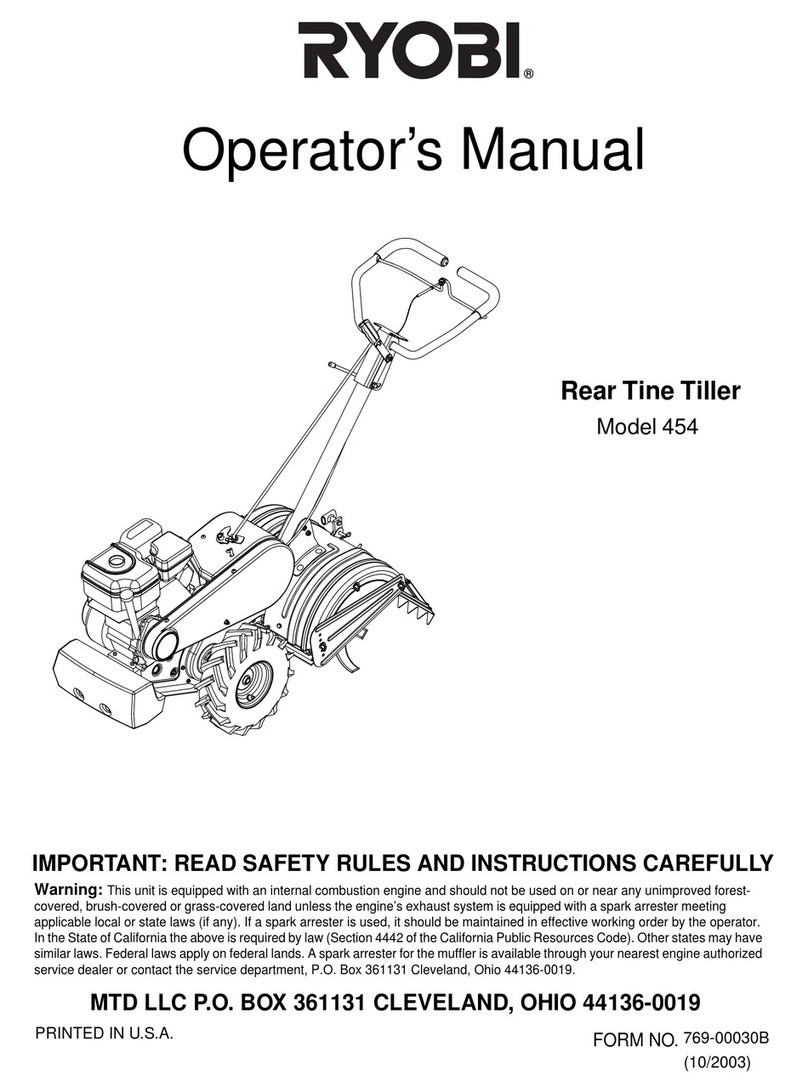
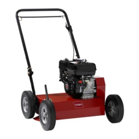
Mighty Mac 824 RT User manual

MIGHTY MAC
·z
MODEL 824RT RE AR-TINE TILLER
OWNERS
MANUAL
Phone: 215-495-7181
AMERIND-MacKISSIC
P,O, Box 111
Parkerford, Penna,
19457
Form 824-77

ASSEMBLY INSTRUCTIONS
Your MIGHTY MAC tiller has been shipped to you almost completely assembled, leaving only
the handles and control rods to install. Before beginning assembly, make sure all parts have been
received and are in good condition. If there are shortages or damage, notify the company from whom
you bought the machine, and the delivery agent at once.
(Note: In the following instructions, the "item" number refers to the number encircled for that part
in the illustrations).
1) Release the shipping straps holding your tiller to the skid.
2) The handles and swivel assembly (item
19,
figure
1)
have been bolted to the right side frame of
the tiller for shipment. Remove the shipping bolt asshown in figure 1.
3) Install the swivel assembly to the tiller, asshown in figure 2 using the nut provided.
Fig. 1
Fig. 2
4) Position the handle height adjusting bolts asshown in Fig. 3. Use the shipping bolt and nut from
(2), above, and the matching bolt and nut from the small bag attached to the engine. We would
suggest you set the handles a little higher than a comfortable height to compensate for them
dropping a few inches when the Tines are in soil.
5) Install the Clutch Rod Swivel, (item 49, fig. 2) through the hole provided in the clutch lever plate
(item 44, fig. 2).
6) Insert the wheel engagement rod assembly, item 32, in the wheel engagement lever asshown in
fig. 14 using the
1/8/1
x
1/1
cotter pin from the small bag.
7) Install the throttle control assembly to the handle brace plate. Install the throttle cable clamp
(item 17, fig. 15), as shown.
-2-

-n
cpO
~
w
G'
~
I
I
~
f
()
I
t1'
f -

8) Remove the drag
bar
(item 13, fig. 6),
lift the hinged foot guard from it's
shipping position and re-install the foot
guard asshown in fig. 4.
9) Service the tiller transmission by
adding five
quarts of #90 gear lube or
SAE 50 wt. motor oil. The transmission
fill plug (item 64, fig. 5) is located on
the upper right side of the transmission
case.
10) Be sure to service the engine as
specified by the engine manufacturer
by filling the crankcase with 2% pints
of SAE 30 (or 10W30 or 10W40)
motor oil. Fill the gastank with
unleaded or regular gasoline.
Fig. 5
11) Your tiller now should appear as in fig. 6, below. Be sure to acquaint yourself thoroughly with the
Operating Instructions before using your tiller.
'~-""'l'O
":-..'..'•..., . .' ':.:_.'.'.',,'; : >-
"""<' •.-"
,.",-
,',
-'
,
6
Fig. 6
-4-

'.
('"
,i' ,
.
,-
OPERATING INSTRUCTIONS
Your Mighty Mac 824 RT tiller has been designed to be the smoothest operating tiller possible. It is
very easily controlled but, as with any machine, requires that you
familiarize
yourself with its features
-and
follow a few important rules to get the most from it.
To operate your tiller SAFELY, there are several cardinal rules you must follow:
1) NEVER ATTEMPT
TO TILL WITH THE WHEELS DISENGAGED.
2) NEVER START
THE ENGINE WITH THE CLUTCH ROD (item
46, fig. 12)
ENGAGED IN
FORWARD OR REVERSE DRIVE.
3)
NEVER PUSH DOWN ON THE HANDLES HARD ENOUGH TO RAISE THE WHEELS
OFF THE GROUND.
To understand the importance of these rules, you should understand that the wheels are not intended
to pull the machine along; rather, they are there to hold back
against
the tines pushing the tiller forward.
For this reason, the wheels must be engaged and on the ground at all times; otherwise, the tines will
push it along too fast and the
tiller
will be out of control. Obviously, this creates a potentially
dangerous situation.
We have made
it
possible to
disengage
the wheels to make it easier to move the
tiller
about
with
the
engine "off". This is particularly useful in maneuvering the tiller in confined areas such as your garage
or tool shed or in moving it to and from your garden.
You may feel that the
tires
are installed backwards from the conventional way
tires
of this type
-are used. They are, however, correct as shown, because
oftheir function
of holdlngthe machTne -back:-
To start your
tiller
and get under way, first make sure the engine crankcase and tiller transmission
::=--=-_---==--=:case are:properl
v
f
lied with lubricant.
T
hen:---- -----:------.--------- ------------------: _
1) Make sure the clutch rod is in neutral.
2) Make sure the sheels are engaged by pushing "in" on the wheel engagement rod assembly, item
32
(fig.
8)
and rolling the tiller ahead slightly until the wheels "lock". If
it
will roll
2
inches, the
wheels are not yet engaged. Continue to push
in
on the wheel engagement rod and roll the machine
forward until the wheels engage.
3)
Open the engine throttle about half way and close the choke as shown in fig.
7.
Fig. 7
-5-

4) Pull the starter rope to start the engine. Open the choke as the engine warms.
5) Set the throttle to the
desired engine speed. We
would suggest you start off
at a slow speed until you
become more familiar with
the performance of the
tiller and then adjust it to
your preference.
6) To engage the clutch for
forward drive, push the
clutch rod, item 46, forward
as far as it will go with mild
pressure. The clutch will
remain engaged in forward
drive until you pull the
clutch rod back to neutral.
7) To engage the clutch for
reverse drive,
pull back on
the clutch rod until reverse Fig. 8
is engaged. It will be necessary for you to hold the clutch rod in the reverse position. When you release
it, it will automatically spring back to the neutral position. This safety feature prevents the tiller from
backing in to you should you stumble or fall.
(Note: to prevent excessive belt wear, you should pause for a moment in neutral when changing from
forward to reverse).
I·
-6-

·
.,'
8'j'
To swing the handles approximately
30°
right or left, simply raise the handle swivel lever, item
20,
as
shown in fig. 8 and swing them to the position provided. The handle swivel lever will drop
into a matching slotwhen the proper postition is reached.
9}
To adjust the drag barto control tilling depth, pull the drag bar lock pin, item
29,
out (to the left)
as illustrated in fig,
9.
Slide the drag bar up or down, asdesired, to the preferred setting. Release
the lock
pin and make sure it engagesone of the holes in the drag bar.
Fig. 9
You will find that your tiller will till deeper with a lower drag bar setting. The drag bar servesto hold
the machine back allowing it to till more in each spot. By raising the drag bar, the tiller can move
forward easier and won't till as deeply.
It is very important that you remember the critical rules mentioned earlier:
1) NEVER ATTEMPT TO TILL WITH THE WHEELS DISENGAGED. (SEE STEP 2, ABOVE, TO CHECK FOR
WHEEL ENGAGEMENT).
2) NEVER START THE ENGINE WITH THE CLUTCH ROD ENGAGED IN FORWARD OR REVERSE DRIVE.
3) NEVER PUSH DOWN ON THE HANDLES HARD ENOUGH TO RAISE THE WHEELS OFF THE GROUND.
J
.1
:1
,j
,1
:~
lJ
t
-7-

'lr B7
ePQOCKET---'~4
·A:'Q~~~.:l m
,.0<.,.
fl
IB
~~~~~~W 4rL~~~~~ml--
--~=========i=·..
==~====--l--+-
--++-.--+----+1---11-
: -."~oo.-_"
I--~
I --
1
1
I'
I'
I:
II
1
I
: I
f
1
'I
15~;
911.'
-. 15 1
L.H.I'"J<A.ME.
701-0183
14
1
Q.H.
i=RAME.
701-0182
'l~
I
INPUT 5HAFT S".bCE.1C
701-0197
-f64
I
peD~Ib'J-LTEO
07.0'0011·-'
-
.3
I''0'' RING
A"","5'Y.
63
I
9~1;.~E.v.;-t
701-0207
981
r=
C.~~T£Iia.A.T&
701-010'"
97 1
-ST.1:~\..EQ~ ••~U"jE.
701-010~
'lto 4
gHl.~~~~~
701-0107
'lIS 2
HeX.
I1D.NUT 7/16-14
94 2
He.~,Ho.C'\'P
Sew. 7/1b-14)(,.~ L..6.
CJ~
2
l -lT~~~~ATE.
701-0100
- 21 oI
REVE.1<5E. BEL.T
030-0131
- 25
7.
D~1\JE. B~LT
050-0100
-1.1
1
'Soc. Ho , S~T SeW•
'6 I(Q-18l
'?/I(Q'LG.
- 62 1
K~Y
>/lbxl'h·L.6.
- 61 I
TR~t~I~e.IOt-.l
701-01715
"12
1
).,Io.40CI1A1N,5d.PITCH
Oe,O-OI'2. 5
91 I
NOI40CHAI~J(;'bPITCH
030-0124
90 1
No.A.OCH,b,I~,50P1T'-H
0i >0'012.
69
I
j.Jo,~OCHAlNJ4oPITCH
osc-c.oe
66
IIN~UT·" lHAFT
PLUG
020-0035
67 I
5/ 1~')(\II4'i..C: , ROLL. PIN
' 701-00B~
6•••
1
If.JPoJT '.OHA..FTSE.AL
701-0060
6~
2
INPUT ~HAFT 61016,
701-0104
84
I
IhiPUT ~PQOCKE.T
701-0076
I::s~
~I- -:LNPUT";H~T 701-0164
- bO
I
;rAM
NUT
3/8-10
- 5"
I
BALL. PLUNGE.Q
701-007&
8"2.
I
WHEE.L E»3oAGE.'O·RING
70J-{1074
81 1GRlpCO NUT 3/B-16
-'35
I
WHEt\.
EHGA\JE,'5l'l~FT
701-007'2
7") I
WHEEL E.NGA,Ge..yO~
701-0070
76 I RETAINING"" >.IG 701-0D~~
772
ROTO~ ~PA.CEQ.
701-0014
7';'
1. TINESHAFTSHIM 701-01l~
7 l I TINE'SHAFTAS'#. 701-0101
74
I
Wt1EE:Lp~~~e
2.~~~
701- 00ID6
Ln>
1WHE't~~\lJl~gt<OCV::ET
701-01610
71
e
vJHUI..,TI~E SH~T -;'EAL.
a2e eeer.
o..po...
OO.l~
71
4.
WHE.LI-1T\NE 'foH"I=T
ees.
O~-OCl~1
70 I
WHUI. OQ.IVE. ~11"'FT
701-0195
-r
l
45
GRIR:.O NUT
1/41.-'20 GQ,o
-r
K
45
CA..SE. BOLT
1/4--'20y. 6/e:L.e,GQ.,Q
69 1
CA."OE
6A5kET
701- 0072>
';'8
1CA'SE. L.H. 701-0199
7
I
CASE.1R.H.
701-0I'1B
NO.
QTY.
PA.Q.T
NAME.
P,,"'TNO.
.,.,.
..
"
.....
,
AMERIND-MacKISSIC Inc
~«,•.•~.
T'" ..."."----
FULL
.,'.O"IO ••" ,~
'"'C<'O~H
·"·CASE ASS'V.
FOR
824RT
-
.~."c."
o;~:12_76 r-·"'~·HUM~~'
701-0160
f,i\
I,
"/
~
I'l
rr
~
----
~
~
~t:..
\",
tfL,) ,
V
_. 91
...
1(69
~"
II
®
L.H. "5\ClE..
90)
~.
®
--R.H,SIDE.
:-.1":-.
\ >
N ~~ II
C V
nH
II
II
.;>43:
I:
~
~ ~ II I ~
75
l II
"NE--~-++\lfI.';""-
INPUT,
WHEEL
6HA~T ~ SHI FT
t>-eSE.MBL\E.6. NO. 1INTE.RM~DIATE 'i5PROCK:ET
<l=
TINE.
=-HAFT
A";$EMBLIE.$
·9·
91

MAINTENANCE INSTRUCTIONS
,.
{
Your Mighty Mac tiller should require little routine maintenance or repair other than that necessary
for gasoline engines. These suggestions should help you keep your tiller running at peak efficiency:
Belt Tension Adjustment - Problems in the drive system can be due to a number of unusual conditions
that may be qu ite different from other belt drives you've encou ntered. Consu It the gu ide on page 11
before attempting to correct any problems or make adjustments.
Fig:10
-10-
,"
.:
...
I'
r
I
I
••
I
I
. ~:.
I

"
I ~
'.
'
"
.
,
DRIVE BELT PROBLEMS AND HOW TO CORRECT THEM
NOTE: Before proceeding with analyizing the cause of any, problem and attempting to correct it, you should make sure
the enqi ne is in the correct location for the length of your belts. With the belt guard removed, press down on all
three belts so that they touch the horizontal tube on the belt engagement lever, item 42, fig. -10. The forward
idler pulleys, nos. 51 &'52 shouldonly move about
~"-%".
If more movement is observed, the engine should
be moved backward
1/16 ~1/a
by
loosening the engine base plate as shown in fig. 13. Whenever the engine is
moved, it will be necessary to re-adjust the linkage as shown in fig. 11 to insure the clutch will stay engaged in
forward drive. It is essential that the engine be in the correct position before proceeding.
PROBLEM CAUSE REMEDY
Extreme Belt Shrinkage Slide engine base rearward 1/16"-1/8",
Forward readjust linkage (fig. 11)
Drive Won't Clutch rod spring beneath operating Back off collar (item 48), fig. 12
panel too tight
Stay Engaged Improper linkage adjustment Adjust as shown in fig. 11
Forward Clutch Rod spring beneath operating Tighten collar (item 48), fig. 12
panel too loose
Drive Does Slide engine base rearward 1/16"·1/8",
not Disengage Belt shrinkage readjust linkage (fig. 11)
Reverse Drive Insufficient reverse Reposition reverse idler pulley
Slips
-~
--
..
belttension ~
-- --
--~
--
(item 52, fig.-1O)--- -
~
--
- --
-----
--_
..
_._-
----.----
Reverse _SlidEulngintLbase rearward_JLtQ':~:.lL8-'-', _
': drive~d:Qes--~=-=--==== =~-Re'{e se-::t>..el.ts_hrinkag~~=_________________
not disengage -readjust forward linkage (fig:--1-1)-----
-.
--
-
--------_
..
-._--
-
-
-
Engine stalls
with smoke All belts are too tight Slide engine base rearward and
and/or noise in readjust all linkage
belt area
One or both Engage forward drive and sight
forward belts along belts to verify they are
smoke but Pulley misalignment parallel with frame. If they are
linkage appears not, correct by moving the engine
normal pulley in or out as required.
.-
Reverse belt Engage
reverse
drive and sight
smokes but Pulley misalignment along the belt as above. Correct
linkage appears by moving the engine pulley in or
normal
-
~
out as required.
Pushing clutch lever
to forward drive Reverse belt has slipped to Return reverse belt to top of reverse idler
position engages
reverse; clutch beneath
reverse
idler pulley pulley as shown in fig. 10.
in reverse
position does
nothing
When shifting
from reverse Clutch rod spring beneath operating Tighten collar as shown in fig. 12.
to neutral, panel too loose.
forward drive
is engaged
-11-

-12-

to. e'
{6 ~
I ~,
'..
....
.
\,
"
,.. ~ r
e-,
.'
Fig. 13
Wheel engagement Adjustment-
If the wheels tend to slip into the neutral position, the wheel engagement ball plunger, (item 59, Fig.
14) can be adjusted to hold the wheel engagement shaft, item 35, more firm Iy. Loosen the lock-nut as
shown in fig. 14 and carefully turn the screw in until it seats against the wheel engagement shaft (turn
the screw gently so as not to damage the spring inside). When the screw is seated, back it off
%
turn.
Tighten the lock nut.
Fig. 14
-13-

Transmission Lubricant-
The level of the lubricant in the transmission should be checked periodically as shown in fig 1'5. The
lubricant in the transmission case should reach the level of the screw located on the lower front of the right
side of the transmission as shown. Remove the screw and check that the level is at or near the hole. Add
sufficient #90 gear
lube
or SAE 50wt motor oil to bring the level up, as required.
( .\?1~>~;
.~' t ,'~
1
trJ,
r : \
I ~
I .
~12('~~:.
Engine-
Be sure to follow the engine ,
manufacturers maintenance recorn-]
mendations and specified oil
change intervals.
If your engine seems to be
losing power noticeably, it may
be due to a dirty air filter.
Remove the air filter element
and tap to remove loose dirt.
Replace every 50 hrs. or more
often under dusty conditions.
Fig. 16 illustrates how to
adjust the idle speed of the
engine. Other adjustments
should only be made by a
qualified mechanic.
Fig. 15
-14-

: .•: )'1,
.c..',,:~ . ~
• _. 0.
(>1
Item No.
t.
'11>
701-0153
Part No.
Qty.
Description
1 701-0161 8 H.P. Engine 1
2701-0160 Transmission Assembly 1
3 701-0083 Handle Bar Assembly 1
4701-0095 R. H Tire & Rim Assembly 1
5 701-0096 L. H Tire & Rim Assembly _ 1
6
701-0136~ Outside Tine, L.H
. if
t.lo-..)
'\o\-O~\O
\.. rt
~,~t
t.l.ts, 1
87 770°1'-_°00'338'~-\" Ou~side ine, R.H ~~ ~""
""'e\_o~h\
~~~'N~
~SS1
1
.•• Inside Tine, L.H 1
9 70'-0039
JIf ~
Inside Tine, R.H 1
10 701-0177 Tine Shroud
&
Foot guard 1
11 701-0155 Belt Guard 1
12 701·0097 Nose Weight 1
13 701-0119 Drag Bar 1
14 701-0182:~;·.. R.H Frame
'.c"''''
·1 ---,,,, ....
~~ 6~~~g6~~ "
ih~~~~:~~ntrol Assembly;.,~fd::: ".. ~•. ,~'"., , •
17 020-0026 Throttle Control Clamp 1
18 701-0124 Handle Swivel Base 1
19 701-0125 Handle Swivel Bracket
1
20 701-0126 Handle Swivel Lever 1
21 701-0171 Engine BasePlate 1
22 701-0170 Belt Guide Plate 1
23 701-0167 ~·'.~Forward Drive Pulley 1
24 701-0156 Reverse Drive Pulley 1
25 030-0130 3V600 Forward Drive Belts
2
26 030-0131 A48 Reverse Drive Belts 1
27 701-0186 Front Belt Guard Bracket 1
28- 701-018r-Rear BeltGuardBracket ..
1-'- ..
29 701-0150 Drag Bar Lock Pin 1
30 701-0128 " Drag Bar Lock Pin Spring 1
_-'----_-.-._.---aL__ ..
301-00-,-3'=--=---_-.----·9/16" L:G mag-BarS'-;;cp-::-:ac;:-::e:-:::r-·-.-.-.._-_-__-_.-._-.~~-_..-.- __-_----- ..
---.--.------.---2'--------
32- 701-0188 Wheel Engagement Rod-Assembly ·1
33 701-0113 Wheel Engagement Lever 1
34 701-0114 Wheel Engagement Link 1
35 701·0072 Wheel Engagement Shaft
1
36 701-0185 Vinyl Grip 1
37 701-0127 Handle Swivel Lever Grip 1
38 701-0192 Handle Grip 2
39
%
x 1 %" Lg Forward Drive Pulley Key 1
40 No.6 Forward Drive Pulley Woodruff Key 1
41 5/16 - 18 x 5/16 Lg Forward Set Screw 3
42
43
44
45
46
47
48
49
50
51
52
53
54
55
56
57
58
59
60
61
62
63
64
65
66
67
701-0181
701-0149
701-0158
701-0159
701-0196
701-0190
701-0191
701.0157
701-0168
701-0172
701-0147
701-0165
701-0164
701-0144
701-0154
701-0189
701-0135
701-0075
3/8 - 16
701-0175
3/16 x1'/," L.G.
5/16 - 24 x 3/8" L.G.
#01-11
020-0011
3/8 - 16 x
%
3/8 - 16
Clutch Assembly
Forward and Reverse Idler Pulley Engagement Lever
Clutch Lever Mounting Bracket
Clutch Lever
Spacer (for no. 44)
Clutch Rod Assembly
Clutch Rod Spring 8" Long
Clutch Rod Collar
Clutch Rod Swivel
Forward Drive Idler Pulley No.1
Forward Drive Idler Pulley No.2
Reverse "V" Idler
1
Forward and Reverse Engagement lever Spacer
Stand-Off Bolt Shaft (for no. 53)
Forward and Reverse Adjusting Sleeve
Forward and Reverse Engagement Rod
Forward and Reverse Spring
1 5/16 CaseSpacer
3/8 - 16 Ball Plunger
3/8 - 16 Ball Plunger Jamnut
Transmission Pulley
Transmission Pulley Key
Oil Lever Check Screw
"0"
Ring (for no. 63)
Oilfill Plug - vented
Shipping Bolt
Shipping Nut
1
1
1
2
1
1
1
1
1
1
1
1
1
1
1
1
2
1
1
1
1
1
1
1
1
<.
1..--....
1
~~--..
-15-
Table of contents

