Toro GREENS AERATOR 09120 User manual

FORM NO. 3319-713 Rev. B
The Toro Company 1997, 1998, 2001
OPERATOR'S
MANUAL
GREENS AERATOR
MODEL NO. 09120 - 80001
thru 90001 & UP
To assure maximum safety, optimum performance,
and to gain knowledge of the product, it is essential
that you or any other operator of the aerator read
and understand the contents of this manual before
the engine is ever started. Pay particular attention
to the SAFETY INSTRUCTIONS highlighted by this
symbol
The safety alert symbol means CAUTION,
WARNING or DANGER personal safety
instruction. Failure to comply with the instruction
may result in personal injury.

2
FOREWORD
The Greens Aerator has advanced concepts in engineering, design and safety; and if maintained properly, will give
excellent service.
Since this is a high-quality product, Toro is concerned about the future use of the machine and safety of the user.
Therefore, read this manual to familiarize yourself with proper set-up, operation and maintenance instructions. The
major sections of the manual are:
1. Safety Instructions 3. Before Operating 5. Maintenance
2. Set-up Instructions 4. Operation
Certain information in this manual is emphasized. DANGER, WARNING and CAUTION identify personal safety
related information. IMPORTANT identifies mechanical information demanding special attention. Be sure to read
this directive because it deals with the possibility of damaging a part or parts of the machine. NOTE identifies general
information worthy of special attention.
The engine exhaust from this product
contains chemicals known to the State of
California to cause cancer, birth defects,
or other reproductive harm.
OPTIONAL SPARK ARRESTER
In some places a spark arrester muffler must be used because of local, state or federal regulations. The spark
arrester available from your local Toro Distributor is approved by the United States Department of Agriculture and
the United States Forest Service. Order the following part from your local authorized Toro Distributor:
1-Spark Arrester Screen, Part No. 94-5301
When the Aerator is used or operated on any California forest, brush or grass covered land, a properly
operating spark arrester must be attached to the muffler. The operator is violating state law, Section 442
Public Resources Code if a spark arrester is not used.
Whenever you have questions or need service, contact your local authorized Toro Distributor. In addition to having a
complete line of accessories and professional turf care service technicians, the distributor has a complete line of
genuine TORO replacement parts to keep your machine operating properly. Keep your TORO all TORO. Buy
genuine TORO parts and accessories.

3
TABLE OF CONTENTS
Page
SAFETY INSTRUCTIONS 4-5. . . . . . . . . . . . . . . . . . .
SAFETY AND INSTRUCTION DECALS 6. . . . . . . . .
SPECIFICATIONS 7. . . . . . . . . . . . . . . . . . . . . . . . . . . .
LOOSE PARTS 8. . . . . . . . . . . . . . . . . . . . . . . . . . . . . . .
SET-UP INSTRUCTIONS 9. . . . . . . . . . . . . . . . . . . . .
BEFORE OPERATING 10-12. . . . . . . . . . . . . . . . . . .
Activate and Charge Battery 10. . . . . . . . . . . . . . . . .
Check Crankcase Oil 10. . . . . . . . . . . . . . . . . . . . . . .
Fill Fuel Tank with Gasoline 11. . . . . . . . . . . . . . . . . .
Check Hydraulic System Fluid 12. . . . . . . . . . . . . . .
CONTROLS 13. . . . . . . . . . . . . . . . . . . . . . . . . . . . . . . . .
TINE SELECTION 14-15. . . . . . . . . . . . . . . . . . . . . . .
OPERATING INSTRUCTIONS 16-19. . . . . . . . . . . . .
Starting/Stopping Engine 16. . . . . . . . . . . . . . . . . . .
Install Tines 16. . . . . . . . . . . . . . . . . . . . . . . . . . . . . . .
Adjust Coring Depth 16. . . . . . . . . . . . . . . . . . . . . . . .
Check Frame Height 17. . . . . . . . . . . . . . . . . . . . . . .
Operating Procedure 17. . . . . . . . . . . . . . . . . . . . . . .
Check Interlock System 17. . . . . . . . . . . . . . . . . . . . .
Override System 17. . . . . . . . . . . . . . . . . . . . . . . . . . .
Training Period 19. . . . . . . . . . . . . . . . . . . . . . . . . . . .
Before Aerating 19. . . . . . . . . . . . . . . . . . . . . . . . . . . .
Aerating Procedure 19. . . . . . . . . . . . . . . . . . . . . . . . .
Transport Operation 19. . . . . . . . . . . . . . . . . . . . . . . .
Page
Inspection and Cleanup After Use 19. . . . . . . . . . . .
DAILY MAINTENANCE CHECKLIST 20. . . . . . . . . . .
LUBRICATION 21. . . . . . . . . . . . . . . . . . . . . . . . . . . . . .
HOLE QUALITY TROUBLESHOOTING 22. . . . . . . . .
MAINTENANCE 23-29. . . . . . . . . . . . . . . . . . . . . . . . .
Changing Hydraulic System Oil 23. . . . . . . . . . . . . .
Change Transaxle Oil 23. . . . . . . . . . . . . . . . . . . . . . .
Belt Adjustments 23. . . . . . . . . . . . . . . . . . . . . . . . . . .
Adjusting Service Brake 25. . . . . . . . . . . . . . . . . . . .
Check Coring Head Chains 25. . . . . . . . . . . . . . . . .
Servicing Roller Chains 25. . . . . . . . . . . . . . . . . . . . .
Coring Head Timing 26. . . . . . . . . . . . . . . . . . . . . . . .
Removing Coring Head 26. . . . . . . . . . . . . . . . . . . . .
Adjusting Brake Assembly 27. . . . . . . . . . . . . . . . . .
Adjusting Clutch Solenoid 27. . . . . . . . . . . . . . . . . . .
Adjusting Throttle Control Rod 28. . . . . . . . . . . . . . .
Battery Care 28. . . . . . . . . . . . . . . . . . . . . . . . . . . . . . .
Battery Storage 28. . . . . . . . . . . . . . . . . . . . . . . . . . . .
ELECTRICAL SCHEMATIC 29. . . . . . . . . . . . . . . . . . .
HYDRAULIC SCHEMATIC 29. . . . . . . . . . . . . . . . . . . .
MAINTENANCE SCHEDULE 30. . . . . . . . . . . . . . . . . .
IDENTIFICATION AND ORDERING 31. . . . . . . . . . . .
THE TORO PROMISE Back Cover. . . . . . . . . . . . . . . .

4
SAFETY INSTRUCTIONS
Improper use or maintenance of the machine can
result in injury. To reduce the potential for injury,
comply with the following safety instructions.
BEFORE OPERATING
1. Read and understand the contents of this
Operator's Manual before operating the machine.
Become familiar with all controls and know how to stop
quickly. A free replacement manual is available by
sending complete Model and Serial Number to:
The Toro Company
8111 Lyndale Avenue South
Minneapolis, Minnesota 55420
2. Do not allow children to operate the machine. Do
not allow adults to operate the machine without proper
instruction.
3. Before attempting to start engine, disengage
traction drive and move gear shift to neutral.
4. Remove all debris or other objects that might
interfere with operation. Keep all bystanders away from
the work area.
5. Locate and mark all under ground obstructions
such as irrigation components, electrical or telephone
lines.
6. Keep all shields and safety devices in place. If a
shield, safety device or decal is defective or damaged,
repair or replace it before operation is commenced.
Also tighten any loose nuts, bolts and screws to assure
machine is in safe operating condition.
7. Do not operate machine while wearing sandals,
tennis shoes, sneakers or shorts. Also, do not wear
loose fitting clothing which could get caught in moving
parts. Always wear long pants and substantial shoes.
Wearing safety glasses, safety shoes, ear protection
and a helmet is advisable and required by some local
ordinances and insurance regulations.
8. Fill fuel tank with gasoline before starting the
engine. Avoid spilling gasoline. Since gasoline is
flammable, handle it carefully.
A. Use an approved gasoline container.
B. Do not fill tank while engine is hot or running.
C. Do not smoke while handling gasoline.
D. Fill fuel tank outdoors and up to about one inch
(25 mm) from top of the tank, not the filler neck.
E. Wipe up any spilled gasoline.
WHILE OPERATING
9. Start engine when traction drive is disengaged,
and gear shift lever is in neutral.
10. Do not run the engine in a confined area without
adequate ventilation. Exhaust fumes are hazardous
and could possibly be deadly.
11. Using the machine demands attention, and to
prevent loss of control:
A. Use only in daylight or when there is good
artificial light.
B. Watch for holes or other hidden hazards.
C. Do not transport machine close to a sand trap,
ditch, creek or other hazard.
12. If the tines strike a solid object or the machine
vibrates abnormally, shut the engine off. Remove high
tension wires from spark plugs to prevent possibility of
accidental starting. Check coring head and traction
unit for damage and defective parts. Repair any
damage before restarting the engine and operating the
tines. Be sure tines are in good condition and all bolts
are tight.
13. Do not touch engine or muffler while engine is
running or soon after it is stopped. These areas could
be hot enough to cause a burn.
14. Before leaving the operator's position behind
handle or leaving machine unattended, raise coring
head, raise lockup brackets, disengage traction drive,
move gear shift to neutral and shut OFF engine.
MAINTENANCE
15. Disconnect high tension wires from spark plugs to
prevent accidental starting of the engine when
servicing, adjusting or storing the machine.
16. If traction unit must be tipped to perform
maintenance or an adjustment, drain gasoline from
fuel tank and oil from crankcase.
17. To reduce potential fire hazard, keep the engine
free of excessive grease, grass, leaves and
accumulations of dirt. Never wash a warm engine or
electrical connections with water.
18. Be sure machine is in safe operating condition by
keeping nuts, bolts and screws tight. Check the tine
mounting bolts and nuts frequently to be sure they are
tightened to specification.
19. If the engine must be running to perform a
maintenance adjustment, keep hands, feet, clothing
and other parts of the body away from the tines and
other moving parts.
20. Make sure all hydraulic line connectors are tight,
and all hydraulic hoses and lines are in good condition
before applying pressure to the system.
21. Before disconnecting or performing any work on
the hydraulic system, all pressure in system must be
relieved by stopping engine and lowering implement to
the ground.

5
SAFETY INSTRUCTIONS
22. Keep body and hands away from pin hole leaks or
nozzles that eject hydraulic fluid under high pressure.
Use paper or cardboard, not hands, to search for
leaks. Hydraulic fluid escaping under pressure can
have sufficient force to penetrate skin and do serious
damage. If fluid is ejected into the skin it must be
surgically removed within a few hours by a doctor
familiar with this form of injury or gangrene may result.
23. Do not overspeed the engine by changing
governor settings. To be sure of safety and accuracy,
have an Authorized TORO Distributor check maximum
engine speed with a tachometer.
24. Engine must be shut off before checking oil or
adding oil to the crankcase.
25. Allow engine to cool before storing machine in any
enclosure such as a garage or storage shed. Make
sure the fuel tank is empty if machine is to be stored in
excess of 30 days. Do not store machine near any open
flame or where gasoline fumes may be ignited by a
spark. Always store gasoline in a safety approved, red
metal container.
26. Perform only those maintenance instructions
described in this manual. If major repairs are ever
needed or assistance is desired, contact an Authorized
Toro Distributor. To ensure optimum performance and
safety, always purchase genuine TORO replacement
parts and accessories to keep the Toro all TORO.
NEVER USE WILL-FIT" REPLACEMENT PARTS AND
ACCESSORIES MADE BY OTHER
MANUFACTURERS. Look for the TORO logo to assure
genuineness. Using unapproved replacement parts
and accessories could void the warranty of The Toro
Company.
SOUND PRESSURE LEVEL
This unit has an equivalent continuous Aweighted
sound pressure at the operator ear of: 92 dB(A), based
on measurements of identical machines per Directive
84/538/EEC and amendments.
SOUND POWER LEVEL
This unit has a sound power level of: 104 dB(A)/1 pW,
based on measurements of identical machines per
Directive 84/538/EEC and amendments.
VIBRATION LEVEL
HandArm
This unit does not exceed a vibration level of 8.5 m/s
at the hands based on measurements of identical
machines per ISO 5349 procedures.
6
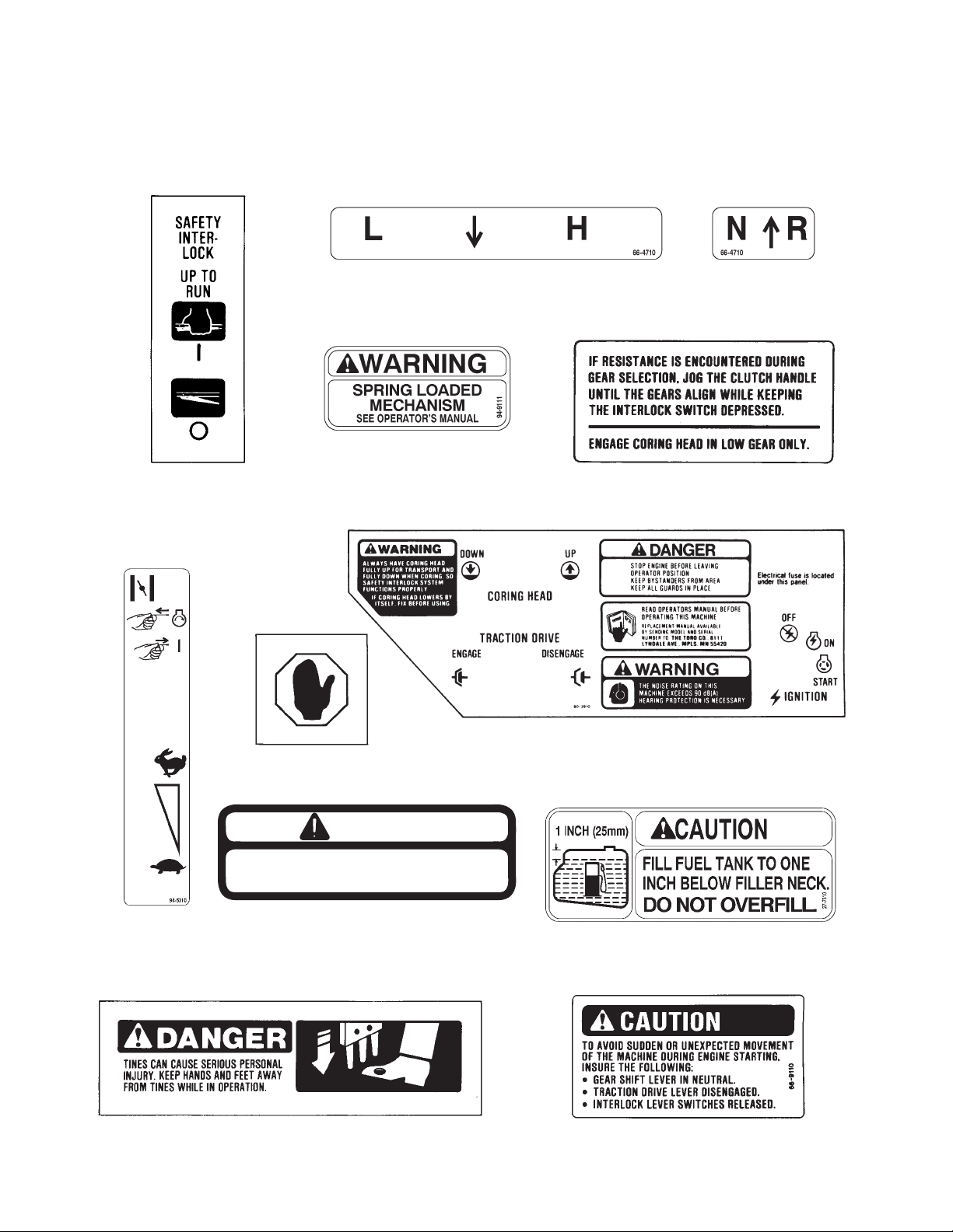
SAFETY AND INSTRUCTION DECALS
The following decals are installed on the machine. If any become damaged or illegible, replace it. The decal part
number is listed below and in your parts catalog. Replacement can be ordered from your Authorized Toro
Distributor.
On Shift Lever Retainer
(Part No. 66-4710)
On Engine
(Part No. 66-9050)
On Brake Handle
(Part No. 59-9860)
On Interlock Switch Assemblies
(Part No. 53-4420)
On Engine
(Part No. 94-5310)
On Control Panel
(Part No. 80-3910)
Near Fuel Tank Cap
(Part No. 27-7310)
On Front of Coring Head Cover
(Part No. 59-9930)
On Engine
(Part No. 66-9110)
On Pulley Guard
(Part No. 94-9111)
On Right and Left side of Frame
and on Coring Head
(Part No. 67-5360)
DANGER
DO NOT OPERATE THIS UNIT UNLESS
ALL SHIELDS ARE FIRMLY SECURED.

7
SPECIFICATIONS
Engine: Briggs & Stratton, Vanguard, 4 cycle, air
cooled, 2 cylinder 16 hp @ 3600 rpm, 29.3 cu. in
displacement. Electric start. Large capacity dual
element air cleaner. Full pressure lubrication 3.5 pint oil
capacity. Solid state electronic ignition.
Electrical: 12 volt battery, 32 amp-hour. 16 amp
alternator. Ignition switch and interlock switches on
control handle, transmission and coring head clutch.
Fuel Capacity: 4.5 gallons unleaded gasoline.
Traction Drive: Double banded V-belt from
mechanical clutch on engine to Peerless Model 2361
transaxle. Two speeds forward and one reverse.
Wheels driven individually by chains from transaxle.
Ground Speed:
1st Gear Forward: 1.04 mph @ 3600 rpm (coring)
2nd Gear Forward: 3.10 mph @ 3600 rpm (transport)
Reverse: 1.88 mph @ 1800 rpm.
Ground Clearance: 4 inches.
Tires/Wheels: Two steering tires (front): 13 X 5.00-6,
2 ply, rib tread tubeless.
Two drive tires (rear): 18 X 9.50-8, 4 ply, Rib Terra
tubeless. Drop center demountable rims, greaseable
tapered roller bearings.
Recommended tire pressure for front and back tires
is10 psi.
Frame: Welded steel construction tricycle.
Service Brake: Disc type mounted to transaxle.
Controls: Traction clutch, coring head hydraulic lift
and key switch on control console. Throttle and choke
on engine. Transaxle shift lever on frame. Interlock
switches and service brake on steering handle.
Implement Drive: Triple banded V-belt from engine
to coring head.
Coring Unit Construction: Welded steel frame
construction with four crankshafts mounted in
precision ball bearings. Crankshafts drive four coring
arms/tine heads.
Drive: No. 50 O-ring sealed roller chain from
countershaft to coring crankshafts.
Lift: Single hydraulic cylinder powered by a vane type
pump. Control valve actuated by lift control lever.
Tine Heads: 4 individual heads each holding three
tines. Deflector chutes direct cores rearward away
from drive components.
Coring Width: 27 inches
Hole Pattern: 2.25 inches X 2.5 inches
Coring Depth: Up to 3.5 inches.
Tines: Case hardened tubing, hollow tapered design.
5/8" tines standard.12 tines required per unit.
Dimensions:
Length: 76 inches
Width: 55.5 inches
Height: 39 inches
Wheelbase: 44 inches
Weight: 1236 pounds
Optional Accessories:
Windrower Model 09150
Coring Head Stand Model 09152
Tire Scrapers Model 09151
See Tine Chart on page 14 for list of tines.

8
LOOSE PARTS
NOTE: Use this chart as a checklist to assure all parts have been received. Without these parts, total set-up cannot
be completed.
Note: Some parts may already be installed on machine.
Set Screw 1
Key 1 Install Handle Assembly
Roll Pin 1
Rear Wheel 2 Install Rear Wheels
Lug Nuts 8
Tine-5/8" 12 Install on Coring Head
Ignition Key 1
Frame Height Gauge 1
Timing Rods 4 Use to Time Coring Head
Operator's Manual 1 Read Before Operating Machine
Parts Catalog 1
Engine Manual 1
Registration Card 1 Fill Out And Return To Toro
Description UseQty.
9
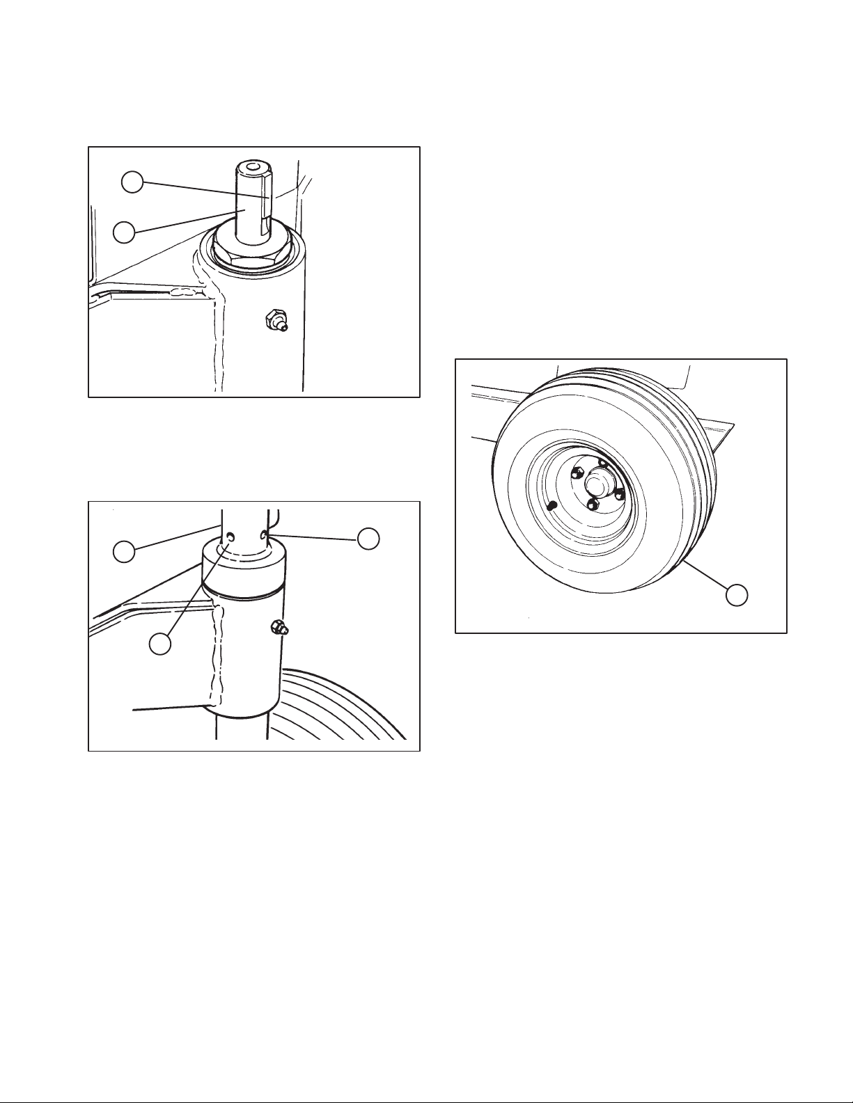
SET-UP INSTRUCTIONS
INSTALL HANDLE ASSEMBLY
1. Insert key into keyway on handle mounting shaft
(Fig. 1).
Figure 1
1. Key
2. Handle mounting shaft
1
2
2. Align keyway in handle assembly with key and
slide handle onto shaft (Fig. 2).
Figure 2
1. Handle assembly
2. Set screw
3. Roll pin
1
3
2
IMPORTANT: Make sure wire harness hangs freely
and is not wrapped around handle.
3. Insert roll pin into mounting hole and drive pin in
until flush with edge of handle assembly (Fig. 2).
4. Apply loctite #242 to set screw. Install screw to
handle assembly and tighten (Fig. 2).
INSTALL REAR WHEELS
1. Secure wheels to spindle hubs with lug nuts
(Fig. 3). Torque nuts to 65-90 ft-Ib.
1. Rear wheel
Figure 3
1
CHECK TIRE PRESSURE
The tires are over-inflated for shipping. Therefore,
release some of the air to reduce the pressure. Correct
air pressure is 10 psi.

10
BEFORE OPERATING
ACTIVATE AND CHARGE BATTERY
1. Since battery is not filled with electrolyte or
activated, bulk electrolyte with 1.260 specific gravity
must be purchased from a local battery supply outlet.
Wear safety goggles and rubber gloves
when working with electrolyte. Charge
the battery in a well ventilated place so
gasses produced while charging can
dissipate. Since the gases are explosive,
keep open flames and electrical spark
away from the battery; do not smoke.
Nausea may result if the gases are
inhaled. Unplug charger from electrical
outlet before connecting to or discon
necting charger leads from battery
posts.
CAUTION
2. Remove wing nuts and washers securing battery
clamp to battery bolts and remove battery from
machine. Remove filler caps from battery and slowly fill
each cell until electrolyte is just above the plates
(Fig. 4).
1. Wing nuts & washers
2. Battery clamp
Figure 4
3
3. Battery pad
4. Support rods
1
2
4
3. Replace filler caps and connect a 3 to 4 amp
battery charger to the battery posts. Charge the battery
at a rate of 3 to 4 amperes for 4 to 8 hours.
4. When battery is charged, disconnect charger from
electrical outlet and battery posts.
5. Remove filler caps. Slowly add electrolyte to each
cell until level is up to fill ring. Install filler caps.
IMPORTANT: Do not over fill battery. Electrolyte will
overflow onto other parts of the machine and severe
corrosion and deterioration will result.
6. Mount battery on battery pad with terminal posts
toward rear of machine (Fig. 4).
7. Secure battery with to battery bolts with clamp,
washers and wing nuts (Fig. 4).
8. Install the positive cable (rubber boot over end) to
the positive (+) terminal and the negative cable (black)
to the negative (-) terminal of the battery and secure
with carriage bolts, lockwashers and nuts. Slide the
rubber boot over the positive terminal to prevent
possible short-out from occurring (Fig.4).
CHECK CRANKCASE OIL
The engine is shipped with 3-1/2 pints of oil in the
crankcase; however, level of oil must be checked
before and after the engine is first started.
1. Position machine on a level surface.
2. Remove dipstick and wipe it with a clean rag. Insert
dipstick down into dipstick tube and tighten. Make
sure it is seated fully. Remove dipstick and check level
of oil (Fig. 5). If oil level is low, add enough oil to raise
level to FULL mark on dipstick.
1. Dipstick
2. Filler cap
Figure 5
1
2
3. Remove filler cap and pour oil into filler neck until
level is at the FULL mark on dipstick. The engine uses
any high-quality oil having the American Petroleum
Institute APl service classification" SE, SF or SG.
Oil viscosity weight must be selected according
to ambient temperature. Temperature/ viscosity
recommendations are:

11
BEFORE OPERATING
F–20 0 20 40 60 80 100
°
C
–30
°–20 –10 0102030 40
32
*SAE 30 oil, if used below 40F (4C) will result in
hard starting and possible engine bore damage due
to inadequate lubrication.
30*
5W30,10W–30
SYNTHETIC 5W20, 5W–30
IMPORTANT: Check level of oil every 8 operating
hours or daily. Initially, change oil after the first 8
hours of operation; thereafter, under normal
conditions, change oil after every 50 hours of
operation and filter after every 100 hours of
operation. However, change oil more frequently
when engine is operated in extremely dusty or dirty
conditions, under heavy load or in high ambient
temperatures.
FILL FUEL TANK WITH GASOLINE
This engine is certified to operate on unleaded
gasoline. Use clean, fresh, unleaded gasoline with
a minimum of 85 octane. Do not mix oil with
gasoline. Purchase fuel in quantity that be used
within to 30 days assure fuel freshness. Use Briggs
& Stratton Gasoline Additive (See your Authorized
Briggs & Stratton Service Dealer for Part No. 5041
or the single-use pouch.)
In countries other than the U.S.A., leaded gasoline
may be used if it is commercially available and
unleaded is unavailable.
Note: Some fuels called oxygenated or
reformulated gasolines, are gasoline blended with
alcohols or ethers. Excessive amounts of these
blends can damage the fuel system or cause
performance problems. Do no use gasoline which
contains Methanol. If any undesirable operating
symptoms occur, use gasoline with a lower
percentage of alcohol or ether.
1. Remove cap from the fuel tank (Fig. 6) and fill the
4.5 gallon tank to within 1 inch from the top with
unleaded gasoline. Install fuel tank cap tightly.
Because gasoline is flammable, caution
must be used when storing or handling it.
Do not fill fuel tank while engine is
running, hot or when machine is in an
enclosed area. Vapors may build up and
be ignited by a spark or flame source
many feet away. DO NOT SMOKE whiIe
filling the fuel tank to prevent the possibil
ity of an explosion. Always fill fuel tank
outside and wipe up any spilled gasoline
before starting engine. Use a funnel or
spout to prevent spilling gasoline before
starting engine and fill tank to about I inch
(25 mm) below the filler neck. Store
gasoline in a clean safety- approved
container and keep the cap in place on the
container. Keep gasoline in a cool, well-
ventilated place; never in an enclosed
area such as a hot storage shed. To
assure volatility, do not buy more than a
30 day supply of gasoline. Gasoline is a
fuel for internal combustion engines;
therefore, do not use it for any other
purpose. Since many children like the
smell of gas, keep it out of their reach
because the fumes are explosive and
dangerous to inhale.
DANGER
1. Vented fuel tank cap
Figure 6
1
2. Wipe up gasoline that may have spilled to prevent
a fire hazard.

12
BEFORE OPERATING
CHECK HYDRAULIC SYSTEM FLUID
The hydraulic system is designed to operate on SAE 10
W-30 engine oil or, as a substitute, SAE 10 W-40
engine oil. The machine's reservoir is filled at the
factory with approximately 2.7 pints of SAE 10 W-30
engine oil. However, check level of hydraulic fluid
before engine is first started and daily thereafter.
1. Position machine on a level surface and raise
coring head to the full up position.
2. Remove dipstick cap (Fig. 7) from filler neck and
wipe it with a clean rag. Insert dipstick cap into filler
neck; then remove it and check level of fluid. If level is
not within 1/2 inch from the full mark on dipstick, add
SAE 10W-30 engine oil to raise level to full mark. Do
not overfill.
3. Install dipstick filler cap onto filler neck.
4. Run engine for approximately 1 minute, recheck
level of fluid and add oil as required.
1. Dipstick cap
Figure 7
1

13
CONTROLS
Choke (Fig. 8) To start a cold engine, close
carburetor choke by pulling choke control outward to
the ON position. After engine starts, regulate choke to
keep engine running smoothly. As soon as possible,
open the choke by pushing it inward to the OFF
position. A warm engine requires little or no choking.
Figure 8
1
1. Choke
2. Throttle
3. Gear shift lever
2
3
Throttle (Fig. 8) Throttle is used to operate engine at
various speeds. Moving throttle upward increases
engine speed FAST; rearward decreases engine
speed SLOW. The throttle controls the speed of the
coring head and, in conjunction with traction clutch,
controls ground speed of the machine.
Gear Shift Lever (Fig. 8) Transmission has two
forward speeds, neutral and reverse, and has an inline
shaft pattern. Do not shift while unit is moving, as
transmission damage may occur.
Ignition Switch (Fig.9) The ignition switch, which is
used to start and stop the engine, has three positions:
OFF, ON and START. Rotate key clockwise START
position to engage starter motor. Release key when
engine starts. The key will automatically return to the
ON position. To shut engine off, rotate key
counterclockwise to the OFF position.
Traction Drive Lever (Fig. 9) Shift to desired gear
and move traction drive lever to engage position to
move forward or reverse. One of the hand operated
interlock levers (Fig.10) must be engaged to shift
traction drive lever. Also, parking brake is automatically
engaged or disengaged with traction drive lever and
interlock lever operation .
Coring Head Lever (Fig. 9) Raises and lowers
coring head and engages and disengages drive.
Figure 9
3
1. Traction drive lever
2. Coring head lever
3. Ignition switch
21
Interlock Lever Switches (2) (Fig. 10) Switches
permit engine operation when coring head is lowered.
They also hold the traction drive lever in engaged
position. One handle switch must be activated before
engaging traction drive or lowering the coring head,
when engine is running.
1. Interlock lever switches
2. Service brake
Figure 10
1
1
2
Service Brake (Fig. 10) Used to slow down traction
operation.
14
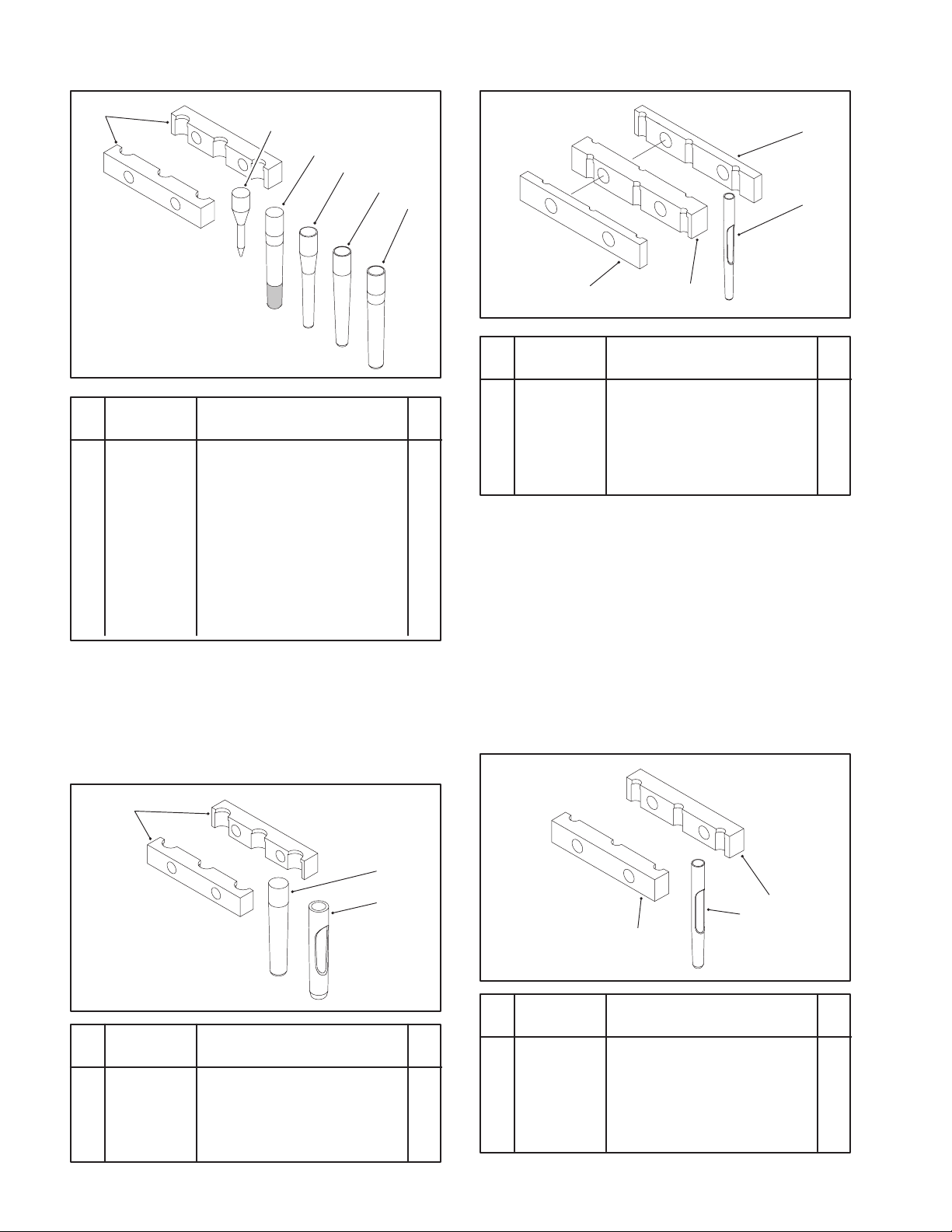
TINE SELECTION
12
3
4
5
6
1 59-2500 Block 8
2 77-5320 Tine - Spiker,
5/16" x 3 1/4" 12
3 59-9770 Tine - Coring, Long Wear
5/8" x 4 3/4" 12
4 59-3690 Tine - Coring,
3/8" x 4 3/4" 12
5 94-3419 Tine - Coring,
1/2" x 4 3/4" 12
6 59-3670 Tine - Coring,
5/8" x 4 3/4" 12
DescriptionPart No. No.
Used
Ref.
No.
1
2
3
DescriptionPart No. No.
Used
Ref.
No.
1 62-4610 Block 8
2 62-4600 Tine - Coring,
3/4" x 4 3/4" 12
3 92-7941 Tine - Open Center,
3/4" x 4 3/4" 12
1
13
2
DescriptionPart No. No.
Used
Ref.
No.
* 94-6823 Kit- 1/4" Open Center Tine
(Opt.) 1
1 94-3421 Block - Outboard 8
2 94-3417 Tine - Open Center
1/4" x 4 1/4" 24
3 94-6822 Block - Inboard 4
1
2
1
DescriptionPart No. No.
Used
Ref.
No.
* 94-6814 Kit - 3/8" Open Center Tine
(Opt.) 1
1 94-3420 Block 8
2 94-3418 Tine - Open Center,
3/8" x 4 3/4" 12
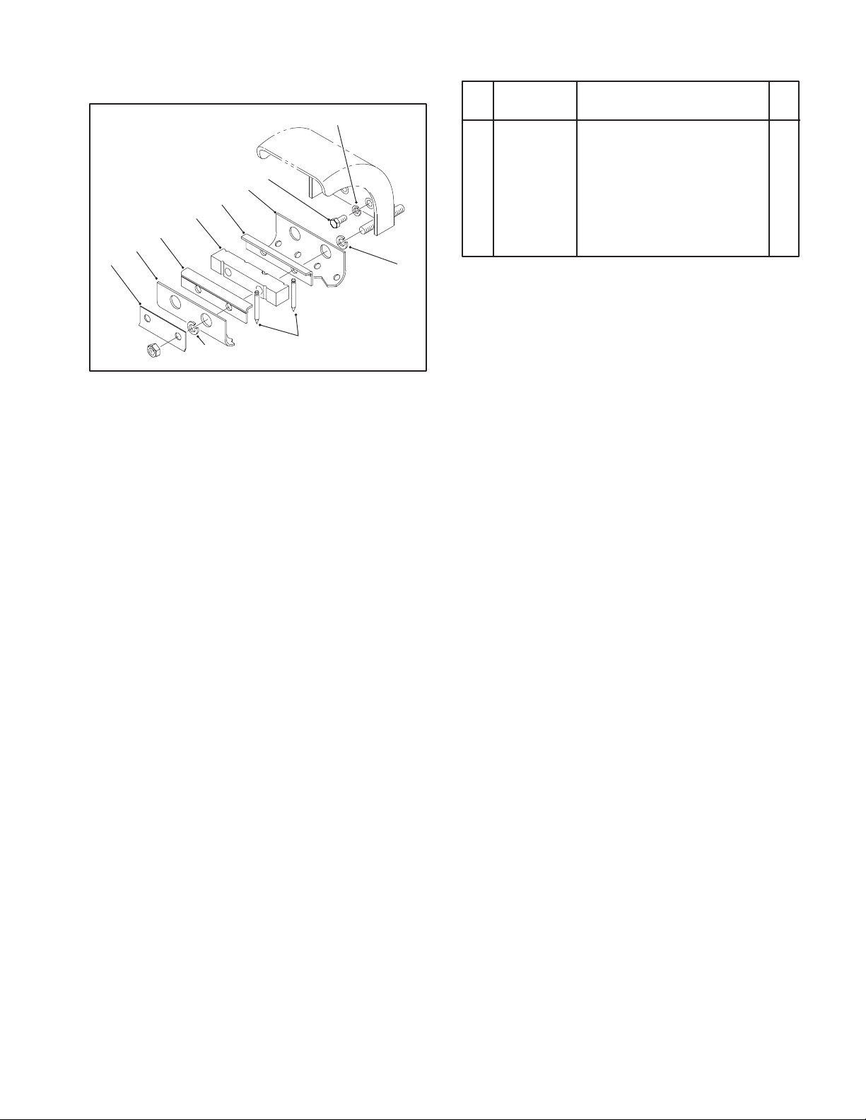
15
TINE SELECTION
1/4" SPIKER KIT - MODEL NO. 09153
1
2
3
4
5
7
2
3
78
61 77-5360 Plate - Holder, Turf 4
2 77-5380 Guard - Turf 4
3 77-5350 Clamp - Holder, Tine 8
4 77-5370 Holder - Tine 4
5 323-4 Screw - HH 16
6 3253-21 Washer - Lock 16
7 3253-7 Washer - Lock 16
8 77-5340 Tine - Spiker, 1/4" x 2 1/2" 28
DescriptionPart No. No.
Used
Ref.
No.

16
OPERATING INSTRUCTIONS
STARTING/STOPPING ENGINE
1. Make sure both wires are installed on spark plugs.
2. Make sure traction drive is disengaged and gear
shift lever is in Neutral.
3. Pull choke lever out to ON position when starting
a cold engine and throttle lever to Mid position.
4. Insert key into ignition switch and rotate it
clockwise to start the engine. Release key when
engine starts. Gradually return the choke lever to the
OFF position (lever all the way in) after the engine starts
and warms up.
IMPORTANT: To prevent overheating of the starter
motor, do not engage starter longer than 10
seconds. After 10 seconds of continuous cranking,
wait 60 seconds before engaging starter motor
again.
5. Make sure coring head is in the raised position.
Note: When engine is started for the first time, or after
overhaul of the engine, transmission or axle, operate
the machine in forward and reverse for one to two
minutes to be sure of proper operation of all parts.
6. To stop the engine, move throttle control
downward to SLOW position and turn ignition key to
OFF".
INSTALL TINES
(Refer to Tine Chart on Page 14 for tine selection)
1. Start the engine: refer to Starting/Stopping
instructions.
2. Move coring head lever to UP" position to raise
coring head.
3. Stop engine and raise lock-up brackets on each
side of chassis (Fig. 11). Lower coring head until it rests
on brackets.
1. Lock-up bracket
Figure 11
1
4. Loosen (2) hex nuts on each tine block until tines
can be inserted. Insert tines, from bottom, until they
bottom out on flange in top of tine block (Fig. 12).
1. Tine block
2. Mounting nut
Figure 12
1
2
5. Tighten mounting nuts to 100-110 ft/Ib. torque
(Fig. 12).
6. Check clearance between tines and slots in turf
guards. If side play is evident in the tine arms, adjust
both wear plates outboard to eliminate the possibility of
the tines contacting turf guard and damaging tines.
1. Tine
Figure 13
1
ADJUST CORING DEPTH
1. Raise coring head and engage lock-up brackets.
2. Loosen jam nut on top of adjusting bracket
(Fig. 14).
3. Thread adjusting screw into bracket to increase
coring depth and out to decrease depth (Fig. 14).
4. Best performance and coring depth is achieved
when distance from end of screw head to bracket is
11/16" (Fig. 14).
IMPORTANT: Do not adjust screw to a setting less
than 11/16" or damage to turf guards may occur.
5. Make sure adjustments are the same on both
sides of coring head and tighten jam nuts.
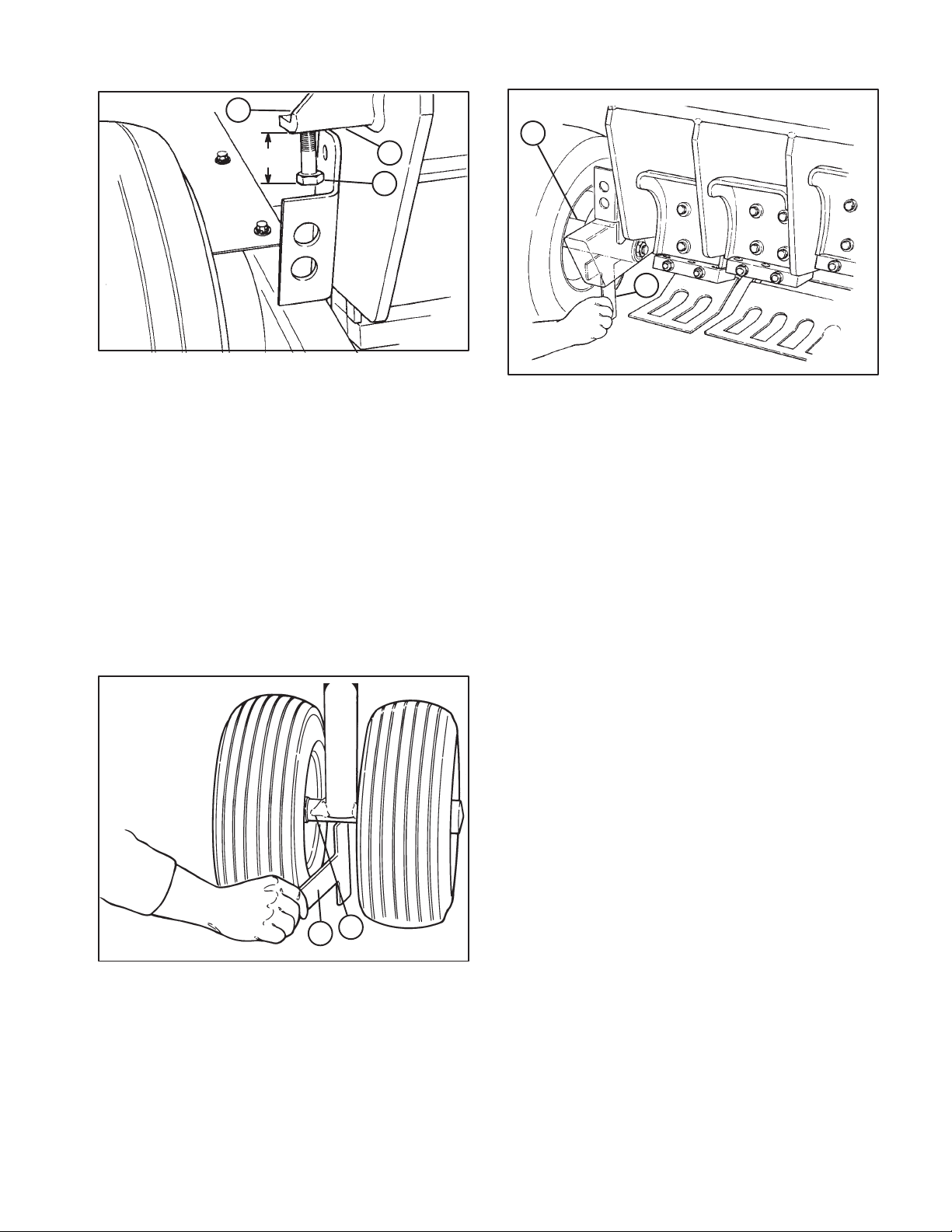
17
OPERATING INSTRUCTIONS
1. Coring depth adjustment screw
2. Adjusting bracket
3.Jam nut
Figure 14
1
2
3
11/16"
CHECK FRAME HEIGHT
1. Position machine on a level surface.
2. Check tire pressure. Tire pressure should
be10 psi. Make sure all tires are equal pressure.
3. Slide short end of frame height gauge under front
axle to verify height. Gauge should contact axle when
on floor. Check both sides (Fig. 15).
1. Front axle
2. Height gauge
Figure 15
1
2
4. Increase or decrease tire pressures to attain
required height.
5. Repeat procedure using long end of height gauge
on each rear wheel spindle (Fig. 16).
6. Regulate tire pressure as required. Minimum tire
pressure is 6 psi.
1. Rear wheel spindle
2. Height gauge
Figure 16
1
2
OPERATING PROCEDURE
1. Make sure wires are installed on spark plugs.
2. Start the engine: refer to Starting/Stopping
instructions.
3. Make sure coring head is in the up position.
4. Squeeze left interlock lever against handle.
5. Move shift lever to L" (low) for Coring or H" (high)
for Transport.
Note: If resistance is encountered during gear
selection, jog the clutch handle until the gears align. Do
not shift gears while machine is moving. DO NOT
FORCE SHIFT LEVER AS DAMAGE WILL OCCUR.
6. Move traction drive lever to engage position.
7. To engage and lower coring head, move coring
head lever to down position and hold until coring head
is completely lowered.
CHECK INTERLOCK SYSTEM
The purpose of the safety interlock system is to prevent
the engine from cranking or starting unless the traction
drive lever is disengaged and the coring head is raised.
It also interrupts engine operation if a handle mounted
interlock lever is not activated.
To check interlock system:
1. Position machine on a flat, open area. Start the
engine: refer to Starting and Stopping instructions.
2. Check traction switch (Fig. 17) with a continuity
tester or ohm meter and replace if damaged. The
switch must be closed when the gear shift lever is in a
gear. The switch must open when shifting between
Neutral, First, and Second gears.
3. To adjust switch, loosen mounting screws and
reposition switch as required.

18
OPERATING INSTRUCTIONS
1. Traction switch
2. Mounting screws
Figure 17
1
2
4. If coring head is in raised position and engine will
not start, or engine continues to run when coring head
is down and interlock lever(s) released, there is a
defect in the interlock system, proceed to step 5.
5. Check coring head switch (Fig. 18) with a
continuity tester or ohm meter and replace if damaged.
The switch plunger must be depressed when the
coring head is in the raised position.
Note: Before coring head switch can be adjusted,
coring head drive belt must be properly adjusted; refer
to instructions for adjusting coring head drive belt on
page 24.
6. If an adjustment to the switch is required, proceed
as follows:
A. Stop engine and lower coring head onto
stand.
B. Remove override pin from storage bracket on
front of coring head cover (Fig. 19).
C. Push down on override lever (Fig. 20) until
holes in lever bracket and coring bracket are
aligned, then insert pin thru holes.
D. Loosen adjusting screw jam nut and (2) flange
nuts (Fig. 18).
E. Turn ignition switch to start position, but do not
start engine.
F. While holding ignition switch in the start
position, tighten adjusting screw until engine
cranks.
G. Release ignition switch and tighten adjusting
screw one more turn.
H. Tighten adjusting screw jam nut and (2) flange
nuts.
I. Restart the engine and raise the coring head.
J. Stop the engine, remove the override pin and
reinstall in storage bracket.
K. Start engine and check all modes of operation.
Coring head should not run when on coring head
lock-up brackets.
1. Coring head switch
2. Adjusting screw & jam nut
3. Mounting screws
Figure 18
1
2
3
OVERRIDE SYSTEM
The coring head is equipped with a release
mechanism which allows the engine to be started
when the coring head is in the lowered position.
1. Remove override pin from storage bracket on front
of coring head cover (Fig. 19).
1. Override pin
Figure 19
1
2. Push down on override lever until holes in lever
bracket and coring head are aligned, then insert pin
thru holes (Fig. 20).

19
OPERATING INSTRUCTIONS
1. Override lever
2. Lever bracket
3. Override pin
Figure 20
1
2
3
3. Restart the engine and raise the coring head.
4. Stop the engine, remove the pin and reinstall in
storage bracket.
TRAINING PERIOD
Before aerating greens with the Greens Aerator, it is
suggested that you find a clear area and practice
starting and stopping, raising and lowering coring
head, turning, etc. This training period will be beneficial
to the operator in gaining confidence in the
performance of the Greens Aerator.
BEFORE AERATING
Inspect the work area for debris and determine the
best direction and pattern to operate machine. Mark all
sprinkler head and obstructions
AERATING PROCEDURES
1. Approach the work area with the gear shift lever in
the L" (low) position.
2. Lower coring head when desired starting position
is attained. Make sure coring head is engaged before
the tines are within one inch of the turf.
3. Use rubber guides hanging from front of chassis to
align rows.
Always have coring head fully raised
when transporting and fully lowered when
coring so safety interlock system func
tions correctly. If coring head lowers by it
self, correct malfunction before continu
ing operation.
CAUTION
TRANSPORT OPERATION
Make sure coring head is in the up position and coring
head lock-up brackets are up. Set the gear shift lever
in the H" (high) position if faster ground speed is
required. Use the service brake to slow the machine
while going down steep hills to avoid loss of control.
Always approach rough areas at a reduced speed and
cross severe undulations carefully.
INSPECTION AND CLEAN-UP AFTER
USE
At the completion of operation, thoroughly wash the
machine with a garden hose without a nozzle so
excessive water pressure will not cause contamination
and damage to seals and bearings. After cleaning, it is
recommended the machine be inspected for possible
hydraulic fluid leaks, damage or wear to hydraulic and
mechanical components and the tines checked for
sharpness. Lubricate grease fittings immediately after
every washing.

20
DAILY MAINTENANCE CHECKLIST
Daily Maintenance: (duplicate this page for routine use)
Check proper section of Operator's Manual for fluid specifications
Maintenance Daily Maintenance Check For Week Of _________________
Maintenance
Check Item MON TUES WED THURS FRI SAT SUN
Safety Interlock Operation
Brake Operation
Fuel Level
Engine Oil
Frame Height
Air Filter/Pre–cleaner
Condition
Clean Engine Cooling Fins
Hydraulic System Oil Level
Unusual Operating Noises
Tine & Stomper Arm
Condition
Hydraulic Hoses for Damage
Fluid Leaks
Tire Pressure
Tighten Loose Fasteners
Lubricate Roller Chains1
Lubricate All Grease Fittings1
Touch–up Damaged Paint
1= Immediately after every washing, regardless of the interval listed.
Notation for areas of concern: Inspection performed by_____________________________
Item Date Information
1
2
3
4
5
6
7
8
Other manuals for GREENS AERATOR 09120
1
Other Toro Tiller manuals


Popular Tiller manuals by other brands


hecht
hecht 746 TRANSLATION OF ORIGINAL INSTRUCTIONS FOR USE

Husqvarna
Husqvarna RTT900 96093000901 owner's manual

AL-KO
AL-KO MH 5065 R operating manual

Craftsman
Craftsman 3.75 HP 17 INCH TINE WIDTH 917.2922 owner's manual

Schiller Grounds Care
Schiller Grounds Care Classen TA18HD Operator's manual

Texas
Texas TV 3 operating instructions


