Mighty Seven DW-401 User manual

Page 4
GERNERAL SAFETY RULES
GERNERAL POWER TOOL
SAFETY WARNINGS
WARNING: Read all safety
1. Keep the work area clean and well lit.
Cluttered or dark areas invite accidents.
2. Do not operate power tools in explosive
atmospheres, such as in the presence of
ammable liquids, gases or dust. Power
tools create sparks which may ignite the
dust or fumes.
3. Keep children and bystanders away
while operating a power tool. Distractions
can cause you to lose control.
ELECTRICAL SAFETY
1. Power tool plugs must match the
outlet. Never modify the plug in any way.
Do not use any adapter plugs with earthed
(grounded) power tools. Unmodified plugs
and matching outlets will reduce risk of
electric shock.
2. Avoid body contact with earthed
or grounded surfaces such as pipes,
radiators, ranges and refrigerators. There
is an increased risk of electric shock if your
body is earthed or grounded.
3. Do not expose power tools to rain or
wet conditions. Water entering a power tool
will increase the risk of electric shock.
4. Do not abuse the cord. Never use the
cord for carrying, pulling or unplugging the
power tool. Keep the cord away from heat,
oil, sharp edges or moving parts. Damaged
or entangled cords increase the risk of
electric shock.
5. When operating a power tool outdoors,
use an extension cord suitable for outdoor
use. Use of a cord suitable for outdoor use
reduces the risk of electric shock.
6. If operating a power tool in a damp
location is unavoidable, use a ground-fault
circuit interrupter (GFCI) protected supply.
Use of a GFCI reduces the risk of electric
shock.
PERSONAL SAFETY
1. Stay alert, watch what you are doing
and use common sense when operating a
power tool. Do not use the tool while tired
or under the inuence of drugs, alcohol, or
medication. A moment of inattention while
operating power tools may result in serious
personal injury.
2. Use personal protective equipment.
Always wear eye protection. Protective
equipment such as a dust mask, non-skid
safety shoes, hard hat, or hearing protection,
used for appropriate conditions, will reduce
personal injuries.
3. Prevent unintentional starting. Ensure
that the switch is in the off-position before
connecting to a power source and/or
battery pack, picking up or carrying the tool.
Carrying power tools with your finger on the
switch or energizing power tools that have
the switch on invites accidents.
4. Remove any adjusting key or wrench
before turning the power tool on. A wrench
or a key left attached to a rotating part of the
power tool may result in personal injury.
5. Do not overreach. Keep proper footing
and balance at all times. This enables better
control of the power tool in unexpected
situations.
warnings and instructions!
Failure to follow the warnings and instruc-
tions may result in electric shock, fire and /
or serious injury.
Save all warnings and instructions for
future reference.
The term “power tool” in the warnings refers
to your mains-operated (corded) power tool
or battery-operated (cordless) power tool.
WORK AREA SAFETY
11

Page 5
6. Dress properly. Do not wear loose
clothing or jewelry. Keep your hair, clothing
and gloves away from moving parts. Loose
clothes, jewelry or long hair can be caught in
moving parts.
7. If devices are provided for the connection
of dust extraction and collection facilities,
ensure that these are connected and
properly used. Use of these devices can
reduce dust-related hazards.
POWER TOOL USE AND CARE
1. Do not force the power tool. Use the
correct power tool for your application. The
correct power tool will do the job better
and more safely at the rate for which it was
designed.
2. Do not use the power tool if the switch
does not turn it on and off. Any power tool
that cannot be controlled with the switch is
dangerous and must be repaired.
3. Disconnect the plug from the power
source and/or the battery pack from the
power tool before making any adjustments,
changing accessories, or storing power
tools. Such preventive safety measures
reduce the risk of starting the power tool
accidentally.
4. Store idle power tools out of the reach
of children and do not allow persons
unfamiliar with the power tool or these
instructions to operate the power tool.
Power tools are dangerous in the hands of
untrained users.
5. Maintain power tools. Check for
misalignment or binding of moving parts,
breakage of parts and any other condition
that may affect the power tool’s operation.
If damaged, have the power tool repaired
before use. Many accidents are caused by
poorly maintained power tools.
6. Keep cutting tools sharp and clean.
Properly maintained cutting tools with sharp
cutting edges are less likely to bind and are
easier to control.
7. Use the power tool, accessories,
tool bits, etc. in accordance with these
instructions, taking into account the
working conditions and the work to be
performed. Use of the power tool for
operations different from those intended
could result in a hazardous situation.
BATTERY TOOL USE
AND CARE
1. Recharge only with the charger
specified by the manufacturer. A charger
that is suitable for one type of battery pack
may create a risk of fire when used with
another battery pack.
2. Use power tools only with specifically
designated battery packs. Use of any other
battery packs may create a risk of injury and
fire.
3. When battery pack is not in use, keep
it away from other metal objects, like
paper clips, coins, keys, nails, screws or
other small metal objects that can make a
connection from one terminal to another.
Shorting the battery terminals together may
cause burns or a fire.
4. Under abusive conditions, liquid may
be ejected from the battery; avoid contact.
If contact accidentally occurs, flush with
water. If liquid contacts eyes, additionally
seek medical help. Liquid ejected from the
battery may cause irritation or burns.
SERVICE
1. Have your power tool serviced by a
qualied repair person using only identical
replacement parts. This will ensure that the
safety of the power tool is maintained.
GERNERAL SAFETY RULES
22
Page 3
SAFETY INSTRUCTIONS
The purpose of safety symbols is to attract your attention to possible dangers. The safety
symbols and the explanations with them deserve your careful attention and understanding.
The symbol warnings do not, by themselves, eliminate any danger. The instructions and
warnings they give are no substitutes for proper accident prevention measures.
WARNING: Be sure to read and understand all safety instructions in this manual,
including all safety alert symbols such as “DANGER,” ”WARNING,” and “CAUTION”
before using this tool. Failure to following all instructions listed below may result in
electric shock, re, and/or serious personal injury.
SYMBOL MEANING
SAFETY ALERT SYMBOL: Indicates DANGER, WARNING, OR CAUTION.
May be used in conjunction with other symbols or pictographs.
DANGER: Indicates an imminently hazardous situation, which, if not avoided,
will result in death or serious injury.
WARNING: Indicates a potentially hazardous situation, which, if not avoided,
could result in death or serious injury.
CAUTION: Indicates a potentially hazardous situation, which, if not avoided, could
result in minor or moderate injury.
NOTICE: (Without Safety Alert Symbol) Indicates a situation that may result in property
damage.
SAVE THESE INSTRUCTIONS!
33
Page 2
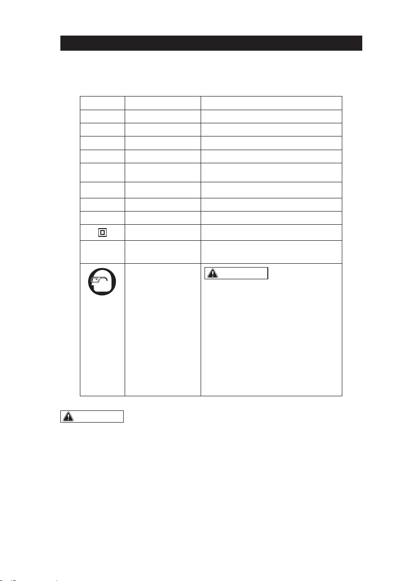
SAFETY SYMBOLS
Some of these following symbols may be used on this tool. Please study them and learn their
meaning. Proper interpretation of these symbols will allow you to operate the tool better and
more safely.
Symbol Name Designation / Explanation
V Volts Voltage
A Amperes Current
Hz Hertz Frequency (cycles per second)
W Watts Power
∿Alternating current Type of current
�Direct current Type or characteristic of current
noNo-load speed Rotational speed at no load
lbs Pounds Weight
Class II construction Double insulated construction
.../min Per minute Revolutions, strokes, surface speed
orbits, etc., per minute
Wear safety goggles WARNING: The operation of any
power tool can result in foreign objects
being thrown into your eyes, which can
result in severe eye damage. Before
beginning power tool operation, always
wear safety goggles or safety glasses
with side shields and a full-face shield
when needed. We recommend a Wide
Vision Safety Mask for use over eye-
glasses or standard safety glasses with
side shields. Always use eye protection
which is marked to comply with
ANSI Z87.1.
WARNING: To ensure safety and reliability, all repairs should be performed by a
qualied service technician.
4
4
Page 6
SPECIFIC SAFETY RULES
SPECIFIC SAFETY RULES FOR
IMPACT WRENCH
1. Hold power tool by insulated gripping
surfaces, when performing an operation
where the
fasterner
may contact hidden
wiring or its own cord.
Fasterner
contacting a “live” wire may make
exposed metal parts of the power tool “live”
and could give the operator an electric
shock.
2. Use only with the chargers and
batteries listed below:
Battery pack Charger
DB-1850 DC-18A
3. Always wear safety goggles and ear
protection when using this tool.
4. Ensure the switch is in the off position
before inserting battery pack. Inserting the
battery pack into power tools that have the
switch on invites accidents.
5. Check the impact socket carefully for
wear, cracks or damage before installation.
6. Bit, sockets and tools get hot during
operation. Wear gloves when touching
them after use.
7. Remove the battery pack before
changing accessories. Accidental starting
may occur, because battery appliances
with a battery inserted are in the operative
condition.
WARNING: Some dust created by
power sanding, sawing, grinding, drilling
and other construction activities contains
chemicals known to cause cancer, birth
defects or other reproductive harm. Some
examples of these chemicals are:
• Lead from lead-based paints
•Crystalline silica from bricks and cement
and other masonry products, and
•Arsenic and chromium from chemically-
treated lumber.
Your risk from these exposures varies,
depending on how often you do this type
of work. To reduce your exposure to these
chemicals: work in a well ventilated area,
and work with approved safety equipment,
such as those dust masks that are specially
designed to filter out microscopic particles.
55

SAFETY RULES FOR CHARGER
1) Before using battery charger, read all
instructions and cautionary markings in this
manual and on the battery charger, the battery
and the product using the battery to prevent
PLVXVHRIWKHSURGXFWVDQGSRVVLEOHLQMXU\RU
damage.
CAUTION: To reduce the risk of electric
shock or damage to the charger and battery,
charge only those lithium-ion rechargeable
EDWWHULHVDVVSHFL¿FDOO\GHVLJQDWHGRQ\RXU
charger’s label. Other types of batteries may
EXUVWFDXVLQJSHUVRQDOLQMXU\RUGDPDJH
2) Do not use the charger outdoors or expose it
to wet or damp conditions. Water entering the
charger will increase the risk of electric shock.
3) Use of an attachment not recommended or
sold by the battery-charger manufacturer may
UHVXOWLQDULVNRI¿UHHOHFWULFVKRFNRULQMXU\WR
persons.
4) Do not abuse the cord or charger. Never use
the cord to carry the charger. Do not pull the
charger cord to disconnect the plug from
receptacle. Damage to the cord or charger
could occur and create an electric shock
hazard. Replace damaged cords immediately.
5) Make sure that the cord is located so that it
will not be stepped on, tripped over, come in
contact with sharp edges or moving parts,
RURWKHUZLVHVXEMHFWHGWRGDPDJHRUVWUHVV
This will reduce the risk of accidental falls,
ZKLFKFRXOGFDXVHLQMXU\DQGGDPDJHWR
the cord, which could then result in electric
shock.
6) Keep cord and charger from heat to prevent
damage to housing or internal parts.
7) Do not allow gasoline, oils, petroleum-based
products, etc. to come in contact with plastic
parts. These materials contain chemicals that
can damage, weaken, or destroy plastic.
8) An extension cord should not be used unless
absolutely necessary. Use of an improper
H[WHQVLRQFRUGFRXOGUHVXOWLQDULVNRI¿UH
and electric shock. If an extension cord must
be used, make sure that:
The pins on plug of extension cord are the
same number, size and shape as those of the
plug on charger.
The cord is properly wired and in good electrical
condition
The size is large enough for AC ampere rating
RIFKDUJHUDVVSHFL¿HGEHORZ
25’ 50’ 100’The Cord Length (Feet)
Cord Size (AWG) 161616
NOTE: AWG = American Wire Gauge
9) Do not operate the charger with a damaged
cord or plug, which could cause shorting and
electric shock. If damaged, have the charger
repaired or replaced by an authorized service
technician at Service Center.
10)Do not operate the charger if it has received
a sharp blow, been dropped, or has
otherwise been damaged in any way. Take
it to an authorized service technician at
Service Center for an electrical check to
determine if the charger is in good working
order.
11)Do not disassemble the charger. Take it to
an authorized service technician at a
Service Center when service or repair is
required. Incorrect reassembly may result in
DULVNRIHOHFWULFVKRFNRU¿UH
12)Unplug the charger from the electrical outlet
before attempting any maintenance or
cleaning to reduce the risk of electric shock.
13)Disconnect charger from the power supply
when not in use. This will reduce the risk of
electric shock or damage to the charger if
metal items should fall into the opening. It
will also help prevent damage to the charger
during a power surge.
14)Risk of electric shock. Do not touch the
uninsulated portion of output connector or
uninsulated battery terminal.
15)Save these instructions. Refer to them
frequently and use them to instruct others
who may use this tool. If you lend this tool to
someone else, also lend these instructions
to them to prevent misuse of the product and
possible injury.
WARNING: Some dust created by power Cutting
contains chemicals known to cause cancer,
birth defects or other reproductive harm. Some
examples of these chemicals are:
Ƶlead from lead-based paints
ƵArsenics and chromium from chemically
reacted lumber.
Your risk from these exposures varies, depending
on how often you do this type of work. To reduce
your exposure to these chemicals: work in a well
ventilated area, and work with approved safety
equipment
6
6

FLINCTIONAL DESCRIPTION
OPERATING CONTROL
The tool is intended for driving in and loosening bolts and nuts.
1. MAIN PARTS
AUTOSTOP
L
H
1/2” Square Driver Vents
Trigger Switch
Direction-of-
rotation Selector
Mode-Selector
Belt Clip
LED Worklight
77

2. TOOL SPECIFICATIONS
DW-401M edo l
2/1 " ( 1 7.2 m m )
M6 ~ M16
iL - oi n
813 Nm / 600 ft-lb
1.48kg
Square driver
Bolt capacity
Battery
Max. torque
Weight
Allowable temperature range ( )0-40
NOTE: Due to
change without prior notice.
SPECIFICATIONS
No-load Speed I:0-1100 RPM
II:0-1600 RPM
III:0-2200 RPM
Impact Rate I:0-1500 I
I
PM
II:0-2500 I
I
PM
III:0-3000 I
I
PM
Torque I: 200 ft.lb 271
N
Nm
m
II: 400 ft.lb 542
N
Nm
m
III: 600 ft.lb 813
N
Nm
m
A
A
u
u
t
t
o
o
s
s
t
t
o
o
p
p
T
T
o
o
r
r
q
q
u
u
e
e
I: 80 ft.lb 108 N
N
m
m
II: 120 ft.lb 163 N
N
m
m
III: 160 ft.lb 217
N
Nm
m
Sound Pressure (dBA)
Sound pressure (Uncertainty K = 3 dB(A)) 98 dBA
Sound power level (Uncertainty K = 3 dB(A)) 109 dBA
Vibration level (m/s2)
(Uncertainty K = 1.5 m/s2)18.2 m/s2
8
8

1. LED FUNCTIONS OF CHARGER
2. POWER BAR
This Lithium-Ion battery pack is equipped with a POWER BAR, which is used to display the battery
pack’s remaining run time. Press the POWER BAR button to display the LED lights. The LED lights
will stay lit for approximately 4 seconds.
NOTE: The POWER BAR can be used whether the battery is attached or removed from tool.
LED INDICATOR BATTERY PACK RED LED GREEN LED ACTION
HI/LO TEMP.
(SEE MANUAL) Hot/Cold battery On Off Charging will begin when
battery returns to 0oC-40oC
DEFECTIVE
BATTERY Defective Flashing Off Battery pack or Charger is
defective
BATTERY
CHARGING Charging Off Flashing Charging
BATTERY
FULL Fully charged Off On Charging is complete
Maintenance charging
3. LOW-BATTERY CAPACITY INDICATOR
gIf LED worklights on the POWER BAR begins
trigger switch on the wrench is depressed,
the battery pack’s power has run out, and the
battery pack should be recharged.
gUnlike other battery pack types, Lithium-Ion
battery packs deliver fade-free power for their
entire run time. The tool will not experience a
slow, gradual loss of power as you work. To
signal that the battery pack is at the end of its
run time and needs to be charged, the power
to the tool will drop quickly. The POWER BAR
when the battery is completely discharged.
When this happens, remove the tool from the
workpiece, and charge the battery pack as
needed.
NOTE: The POWER BAR may also display four
temperature situation.
4. WHEN TO CHARGE THE
BATTERY PACK
GJH/!3
80-100% Charge
60-79% Charge
40-59% Charge
20-39% Charge
Under 20% Charge
Completely Discharged
High/low temperature
The Lithium-Ion battery can be charged at any
time and will not develop a “memory” when
charged after only a partial discharge. It is not
necessary to run down the battery pack charge
before recharging. Remove the battery pack
from the tool when convenient for you and your
job.
gUse the POWER BAR to determine when you
need to recharge the battery pack.
gYou can “top-off” your battery pack’s charge
before starting a big job or long period of use.
9
9

WARNING: If any part is broken
or missing, DO NOT attempt to attach the
battery pack, or operate the tool until the
broken or missing part is replaced. Failure
to do so could result in possible serious
injury.
WARNING: Do not attempt to
modify this tool or create accessories not
recommended for use with this tool. Any
such alteration or modication is misuse
and could result in a hazardous condition
leading to possibly serious injury.
WARNING: Your tool should
never be connected to the power source
when you are assembling parts, making
adjustments,
installing or removing
accessories
, cleaning, or when it is not
in use. Disconnecting the tool will
prevent accidental starting, which could
cause serious personal injury.
ASSEMBLY
UNPACKING
1. Carefully remove the tool and any
accessories from the carton. Make sure
that all items listed in the packing list are
included.
2. Inspect the tool carefully to make sure
that no breakage or damage occurred
during shipping.
3. Do not discard the packing material
until you have carefully inspected and
satisfactorily operated the tool.
ASSEMBLY
TO ATTACH BATTERY
PACK (FIG. 1)
FIG. 1
Attach
1. Make sure that the tool is switched off.
2. Align the raised rib on the battery pack
with the grooves on the bottom of the
Impact Wrench, and then slide the
battery pack onto the tool.
NOTICE: Make sure that the latch on the
battery pack snaps into place and the bat-
tery pack is secured to the tool before op-
eration.
TO DETACH BATTERY
PACK (FIG. 1)
1. Make sure that the tool is turned off.
2. Depress the battery release buttons
located on the front of the battery pack
to release the battery pack.
3. Pull the battery pack out and remove it
from the tool.
Release
Button
Detach
10
10

9
TRIGGER SWITCH (FIG. 2)
Direction-
of-rotation
Selector
Trigger
Switch
FIG. 2
1. To turn the Impact Wrench on, depress
the trigger switch.
2. To turn it off, release the trigger switch.
VARIABLE SPEED
The variable-speed trigger switch delivers
higher speed with increased trigger
pressure and lower speed with decreased
trigger pressure.
DIRECTION -OF-ROTATION
SELECTOR (FORWARD/CENTER-
LOCK/REVERSE) (FIG. 3)
FIG. 3
Forward Reverse
The direction of rotation is reversible and is
controlled by a selector located above the
trigger switch. With the Impact Wrench held in
normal operating position: Position the
direction-of-rotation selector to the left of the
tool for forward rotation. Position the direction-
of-rotation selector to the right of the tool
for reverse rotation. Setting the switch in the
OFF (center-lock) position helps to reduce
the possibility of accidental starting when not in
use.
NOTICE: To prevent gear damage, always
allow the Impact Wrench to come to a
complete stop before changing the direc-tion
of rotation.
NOTICE: The Impact Wrench will not run
unless the direction of the rotation selector is
engaged fully to the left or right.
AUTOSTOP
LH
FIG. 4
Mode Selector
Button
NOTICE: The Impact Wrench is designed
with 3-speed and auto-stop functions, but the
functions are available only when the tool is
operating in forward rotation.
NOTICE: The mode can change only while the
mode-indicator light is on. The mode-
indicator light will be off automatically af-ter
approximately one minute has elapsed.
OPERATION
11
MODE SELECTOR (FIG. 4)
WARNING: When using the Auto-stop
mode, engage the trigger only once. If you pull the
trigger once more, the new torque applied will be
added to the previously applied torque, risking to
damage the bolt/nut. 11

10
OPERATION
1. Attach the battery pack to the Impact
Wrench.
2. Position the direction-of-rotation selector
to the left of the tool for forward rotation,
and press the trigger switch to turn on
the mode-indicator light.
3. Press the mode-selector button; the
speed will change in three steps: low,
medium and high. Press and hold the
mode-selector button for three seconds:
the auto-stop mode is available and the
auto-stop indicator will be on. When
the bolt/nut is sufficiently tight, the
tool stops the impact and rotation after
approximately one second.
4. To turn off the auto-stop function, press
and hold the mode-selector button for
three seconds: the auto-stop will turn
off.
ELECTRIC BRAKE
The Impact Wrench is equipped with an
electric brake. When the trigger switch is
released, the electric brake engages auto-
matically to quickly stop the rotation.
LED WORKLIGHT (FIG. 5)
FIG. 5
LED Worklight
The LED worklight, located on the base of
the Impact Wrench, will illuminate when the
trigger switch is depressed. This provides
additional light on the surface of the
workpiece for operation in lower-light areas.
The light will automatically turn off within 10
seconds after releasing the trigger.
INSTALLING THE BELT
CLIP (FIG. 6)
FIG. 6
Belt Clip
1. Align the rib of the belt clip with the hole
on the base of the wrench.
2. Insert the screw and tighten the screw
securely with a screwdriver (available
separately).
REMOVING THE BELT CLIP
1. Use a screwdriver (available separately)
to loosen the screw that attaches the
belt clip to the wrench.
2. Remove the screw and the belt clip.
12
12

11
OPERATION
INSTALLING AND REMOVING
THE SOCKET (FIG. 7)
FIG. 7
Friction Ring
NOTICE: The friction ring, with certain
plasticity and strength, helps to prevent
the socket from disengaging from the
output drive of the impact wrench during
the operation.
Always use the correct size socket for bolts
and nuts. An incorrect socket will result
in inaccurate and inconsistent fastening
torque and/or damage to the bolt or nut.
1. Lock the trigger switch by placing the
direction-of-rotation selector in the OFF
(center) position.
2. To install the socket, push it onto the
output drive of the tool until it locks into
place.
3. To remove the socket, simply pull it off.
INSTALLING FASTENERS
NOTICE: Always keep the Impact Wrench
at a right angle to the fastener to avoid
damaging the fastener head.
To fasten:
1. Start threading the fastener by hand
onto or into its threaded counterpart
(e.g. nut onto bolt, or bolt into nut or
threaded hole).
2. With the proper impact socket securely
mounted to the Impact Wrench, slide the
impact socket onto the nut or bolt head.
3. Place the direction-of-rotation selector
in the FORWARD position, and select
a suitable speed or the auto-stop
function. Hold the tool firmly while
depressing the trigger switch. The
impact socket will turn the fastener and
the impacting action will begin when the
fastener encounters resistance.
To loosen:
1. With the proper impact socket securely
mounted to the wrench, slide the impact
socket onto the bolt head.
2. Place the direction-of-rotation selector
in the REVERSE position. Hold the
tool firmly while depressing the trigger
switch. The tool will start to impact
immediately.
3. Once the fastener has “broken loose,”
it will start to unthread. Be careful that
you do not allow a fastener to spin
freely once it is no longer engaged with
its threaded counterpart, as it may be
thrown out of the socket.
IMPACTING TIPS
The proper fastening torque may differ
depending on the type or size of the bolt, the
material of the workpiece to be fastened, etc.
NOTICE: Hold the tool straight along the
axis of the bolt or nut.
NOTICE: Excessive fastening torque may
damage the bolt/nut or socket. Before
starting your job, always perform a
test operation to determine the proper
fastening time for your bolt or nut.
Practice with various fasteners, noting the
length of time required to reach the desired
torque. Check the tightness with a hand-
torque wrench. If the fasteners are too tight,
reduce the impacting time. If they are not
tight enough, increase the impacting time.
13
13

12
Hold the tool firmly, and place the socket
over the bolt or nut. Turn the tool on, and
fasten the bolt or nut to the proper torque.
The torque that is required to loosen a
fastener averages 75% to 80% of the
tightening torque, depending on the
condition of the contacting surfaces.
However, if rust or corrosion causes seizing,
more torque may be required.
After fastening, always check the torque
with a torque wrench. The fastening torque
is affected by a wide variety of factors,
including the following:
• Socket
Failure to use the correct size socket will
cause a reduction in the fastening torque.
A worn socket (wear on the hex end or
square end) will cause a reduction in the
fastening torque.
• Bolt
Although the torque coefficient and the
class of bolt may be the same, the proper
fastening torque will differ according to the
diameter of the bolt.
OPERATION
Even if the diameters of bolts are the same,
the proper fastening torque will differ
according to the torque coefficient, the
class of bolt and the bolt length.
• Accessories
The use of a universal joint or an extension
bar (both available separately) will reduce
the fastening force of the Impact Wrench
somewhat. Compensate by fastening for a
longer period of time.
• Technique
The manner of holding the tool or the
material to be fastened will affect the torque.
WARNING: Always wear safety
goggles or safety glasses with side
shields during power tool operations, or
when blowing dust. If operation is dusty,
also wear a dust mask.
WARNING: Do not at any time let
brake uids, gasoline, petroleum-based
products, penetrating oils, etc. come in
contact with plastic parts. Chemicals can
damage, weaken or destroy plastic, which
may result in serious personal injury.
OPERATION
1.BATTERY CHARGING
The battery is supplied partially charged. To
ensure full capacity of the battery, completely
charge the battery in the battery charger before
A fully discharged battery pack will charge
in 50 minutes for DB1850 in a surrounding
temperature between 32° F (0° C) and 104° F
(40° C).
1. Charge the Lithium-Ion battery pack with the
correct charger.
2. Connect the charger to a power supply.
3. Align the raised ribs of the battery pack with
the slot in the charger.
4. Slide the battery pack onto the charger .
5. The charger will communicate with the
battery pack to evaluate the condition of the
battery pack.
6. The POWER BAR LED lights will cycle from
right to left during charging. This is part of the
normal charging operation.
7. After charging is complete, the green LED on
the charger will come on and the POWER BAR
LED lights will go displayed when the POWER
BAR button is pressed while the battery pack is
on the charger.
8. The battery pack will fully charge if left on the
charger, but it will not overcharge.
NOTE: For your convenience, the charger can
operate with most generators and inverters
rated at 300 watts or higher.
14
14

13
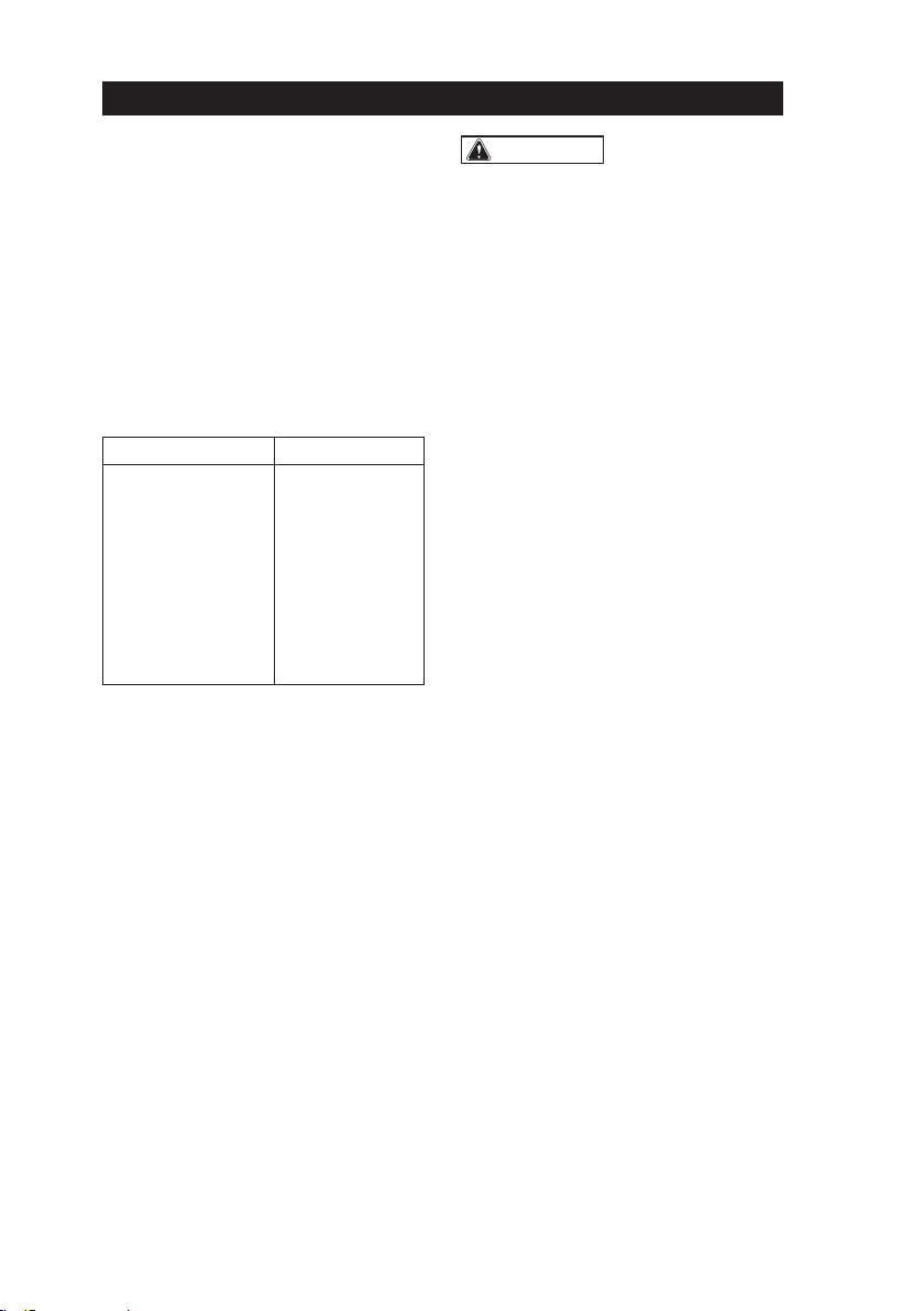
TROUBLESHOOTING
PROBLEM CAUSE SOLUTION
The Impact Wrench does not
work. The battery is depleted. Charge the battery.
The Impact Wrench does
not work and the tool LED
worklight flashes.
The tool is overheated. Allow the tool to cool down.
The impact wrench does not
work and the battery pack
LED light flashes.
The battery is overheated. Allow the battery to cool
down.
ACCESSORIES
NO
MAINTENANCE
The tool may be cleaned most effectively
with compressed dry air. Always wear
safety goggles when cleaning tools with
compressed air.
Avoid using solvents when cleaning plastic
parts. Most plastics are susceptible to
damage from various types of commercial
solvents and may be damaged by their use.
Use clean clothes to remove dirt, dust, oil,
grease, etc.
BEFORE EACH USE
1. Inspect the Impact Wrench, the on/off
switch and the accessories for damage.
2. Check for damaged, missing, or worn
parts.
3. Check for loose screws, misalignment
or binding of moving parts, or any other
condition that may affect the operation.
4. If abnormal vibration or noise occurs,
turn the tool off immediately and have the
problem corrected before further use.
5. Detach the battery from the Impact
Wrench before cleaning or performing any
maintenance. Using compressed air may
be the most effective cleaning method.
Always wear safety goggles when
cleaning tools using compressed air.
LUBRICATION
All of the bearings in this tool are lubricated
with a sufficient amount of high grade
lubricant for the life of the unit under normal
conditions. Therefore, no further lubrication
is required.
15
15

.
Serial Number: Please refer to the tool
Brand Name : Mighty Seven
Cordless Impact Wrench
Item No.:DW-401 (Tool)
to which this declaration applies, complies with these normative documents:
•Machinert Directive : 2006 / 42 / EC
•EMC : 2014 / 30 / EU
and conforms to the following EN standard,
•EN 62841-2-2:2014+AC:2015•EN 62841-1-1:2015+AC:2015
•EN 55014-1:2017 •EN 55014-2:2015
Battery Charger
Item No.: DB1850 (Battery) DC18A(Charger)
to which this declaration applies, complies with these normative documents:
•LVD : 2014 / 35 / EU
•EMC : 2014 / 30 / EU
and conforms to the following EN standards
•EN 60335-1:2012+A11+A13+A1+A14+A2 •EN 60335-2-29:2004+A2+A11
•EN 55014-1:2017 •EN 61000-3-2:2014
•EN 55014-2:2015 •EN 62233:2008 •EN 61000-3-3:2013
Declared in: Taichung, Taiwan
Dated:2020/07/01
Jay Lin
Declared by: QA Manager
Manufacturer:
Mighty Seven International Co.,
Ltd.
No. 70-25, Ching Quang Rd., Wujih Dist.,
Taichung City, 41466 Taiwan
http://www.mighty-seven.com
King Tony France
3 Rue des imprimeurs ZI République Nord 1.
86000 POITIERS FRANCE
TEL: (+33)5-49-30-30-90
E-MAIL: christian.aubineau@kingtony.eu
Signature
Original Language
EC DECLARATION OF CONFORMITY
16
16

Cordless Impact Wrench
ltem No:DW-401
17

NO. PART NO. DESCRIPTION Q'TY
1 DW-401P01 Decorative Cover 1
2 DW-401T02 Tapping Screw(4PCS) 1SET
3 DW-401P03 Front Gear Housing
ASSY 1
4 DW-401P04 Washer 1
5 DW-401P05 Output Shaft ASSY 1
6 DW-401P06 Impact Block ASSY 1
7 DW-401P07 Rear Gear Housing
ASSY 1
8 DW-401P08 Rotor Assembly 1
9 DW-401P09 Stator 1
10 DW-401P10 Left Housing ASSY 1
11 DW-401T11 Rubber Stick(2PCS) 1SET
12 DW-401P12 Right Housing ASSY 1
13 DW-401T13 Tapping Screw(9PCS) 1SET
14 DW-401P14 Electric Assembly 1
15 DW-401P15 F/R Button 1
16 DW-401P16 Indicator Label 1
17 DW-401P17 Switch Button Cover 1
18 DW-401P18 Screw 1
19 DW-401P19 Hook 1
20 DW-401T20 Nut(2PCS) 1SET
ltem No:DW-401
18

17
19
Warranty Card
Manufacturer's limited warranty
M
M
i
i
g
g
h
h
t
t
y
y
S
S
e
e
v
v
e
e
n
n
I
I
n
n
t
t
e
e
r
r
n
n
a
a
t
t
i
i
o
o
n
n
a
a
l
l
C
C
o
o
.
.
,
,
L
L
T
T
D
D
.
.
offers limited warranty to the products
manufactured by
M
M
i
i
g
g
h
h
t
t
y
y
S
S
e
e
v
v
e
e
n
n
and sold by its worldwide authorized dealers. The limited
warranty only applies to products that are defective in material and workmanship and
does not apply to products which have been abused, misused, service representatives.
If there is a defective product of
M
M
i
i
g
g
h
h
t
t
y
y
S
S
e
e
v
v
e
e
n
n
, please send it prepaid to the dealer
where it was purchased from along with address and contact information. Repairs or
replacements are warranted as described above; otherwise, the service of repairs or
replacements will be charged.
Please Keep This card For Warranty
19

Page 4
ALLGEMEINE LEISTUNGSWERKZEUG
SICHERHEITS-WARNUNGEN
Warnung:
ELEKTRISCHE SICHERHEIT
Persönliche Sicherheit
Lesen Sie alle Anweisungen!
SICHERHEIT DES
ARBEITSBEREICHS
1
ALLGEMEINE SICHERHEITSBESTIMMUNGEN
Die Nichtbeachtung der unten aufgeführten
Sicherheitshinweise kann zu Stromschlägen,
Feuer und / oder schweren Körperverletzungen
führen.
4. Niemals das Kabel missbrauchen.
Verwenden Sie niemals das Kabel zum Tragen,
Ziehen oder Herausziehen des Elektrowerkze-
ugs. Halten Sie das Kabel von Hitze, Öl und
scharfen Kanten fern. Beschädigte oder
verwickelte Kabel erhöhen Sie das Risiko eines
Stromschlags.
5. Wenn Sie ein Elektrowerkzeug im Freien
betreiben, verwenden Sie ein Verlängerungs-
kabel, das für den Außenbereich geeignet ist,
es verringert das Risiko eines Stromschlags.
6. Wenn Sie ein Elektrowerkzeug an einem
feuchten Ort betreiben müssen, verwenden
Sie ein Fehlerstromschutzgerät (RCD) für eine
geschützte Versorgung. Die Verwendung
eines Fehlerstromschutzgerät reduziert das
Risiko eines Stromschlags.
Der Begriff „Elektrowerkzeug“ in den Warnungen
bezieht sich auf Ihr netzbetriebenes (schnurge-
bundenes) Elektrowerkzeug oder batteriebetrie-
benes (schnurloses) Elektrowerkzeug.
1. Halten Sie den Arbeitsbereich sauber und gut
beleuchtet. Überfüllte oder dunkle Bereiche
führen zu Unfällen.
2. Betreiben Sie Elektrowerkzeuge nicht in
explosionsgefährdeten Bereichen, z. B. in
Gegenwart von nicht brennbaren Flüssigkeiten,
Gasen oder Staub. Powertools erzeugen
Funken, die Staub oder Dämpfe entzünden
können.
3. Halten Sie Kinder und Umstehende fern,
während Sie ein Elektrowerkzeug bedienen.
Ablenkungen können dazu führen, dass Sie die
Kontrolle verlieren.
1. Seien Sie wachsam. Achten Sie darauf, was
Sie tun, und arbeiten Sie ruhig und überlegt
mit einem Elektrowerkzeug. Verwenden Sie
das Gerät nicht, wenn Sie müde sind, sich
nicht konzentrieren können oder wenn Ihre
Reaktionsfähigkeit durch die Einnahme von
Drogen, Alkohol oder Medikamenten beein-
trächtigt ist. Ein Moment der Unaufmerksam-
keit beim Bedienen eines Elektrowerkzeugs
kann zu schweren Verletzungen führen.
2. Tragen Sie Kleidung, persönliche Schutzaus-
rüstung und immer eine Schutzbrille. Das Tragen
persönlicher Schutzkleidung und -ausrüstung
wie Atemmaske, rutschfeste Schuhe, Helm oder
Gehörschutz verringert das Verletzungsrisiko.
3. Vermeiden Sie versehentliches Zünden.
Stellen Sie sicher, dass sich das Elektrowerk-
zeug in der Position "OFF" (= Aus) befindet,
bevor Sie den Stecker in die Steckdose stecken
und /oder die Batterie anschließen. Das Tragen
des Geräts mit dem Finger am Schalter oder
das Einstecken des Geräts im eingeschalteten
Zustand kann zu Unfällen führen.
4. Entfernen Sie alle Werkzeuge oder
Schraubenschlüssel, bevor Sie das Elektrogerät
einschalten. Ein Werkzeug oder ein Schrauben-
schlüssel in einem beweglichen Teil des Geräts
kann zu Verletzungen führen.
5. Vermeiden Sie unsichere Körperpositionen.
Finden Sie eine sichere Position und halten Sie
Ihr Gleichgewicht jederzeit aufrecht. Auf diese
Weise können Sie das elektrische Gerät im Falle
einer unerwarteten Situation besser steuern.
1. Power Tool Stecker müssen mit der
Steckdose übereinstimmen. Ändern Sie den
Stecker niemals in irgendeiner Weise. Verwen-
den Sie keine Adapterstecker mit geerdeten
Elektrowerkzeugen. Unveränderte Stecker und
passende Steckdosen verringern das Risiko
eines Stromschlags.
2. Vermeiden Sie den Kontakt des Körpers mit
geerdeten Oberflächen wie Rohren, Heizkörpern,
Herden und Kühlschränken. Wenn Ihr Körper
geerdet ist, besteht ein erhöhtes Risiko eines
Stromschlags.
3. Setzen Sie Elektrowerkzeuge weder Regen
noch Nässe aus. Wasser, das in ein Elektrow-
erkzeug eindringt, erhöht das Risiko eines
Stromschlags.
Bewahren Sie alle Warnungen und Anweisun-
gen zum späteren Nachschlagen auf.
20
Table of contents
Languages:
Other Mighty Seven Impact Driver manuals


