Mikuni MY Series Manual

Installation of the heater
.
The Mikuni MY series heaters are blown air diesel fired heaters running off either a
12
or
24
volt DC supply
.
To ensure good service from your heater it is important to install it correctly
paying attention to all the details laid out
within this instruction leaflet
.
Planning the Installation
Take time to plan your installation
!
The heater should be sited in an area where
:
(i
)
It will not have items stored against it.
(
ii
)
It will not be exposed to weather
.
(
iii
)
It is within the parameters set out in this manual regarding fuel and power supply.
(
iv
)
It is within the parameters set out in this manual regarding heater mounting
.
(v
)
The exhaust outlet skin fitting is well clear of the water line.
(
vi
)
The exhaust pipe is not touching anything inside the boat which could be damaged by
heat
-The exhaust pipe does get hot even though it is insulated!
Tools for your installation
:
Here is a list of some of the tools required to help with your installation
:
1.
Electric drill with slow speed
.
2.
Crimping pliers
.
3.
Wire cutters
.
4.
Metric spanners
8
mm to
13
mm
.
5.
Flat blade
& posidrive screwdrivers.
6
.
Sharp knife
.
Application
Hot air outlets
Ducting
Skin fitting
Fuel standpipe
MY
16
95
mm
60
mm
42
mm
22
mm
MY
30
95
mm
90
mm
42
mm
22
mm
Hole saws
-
1
-

The heater is supplied with a stainless
steel
'L
'
shaped mounting bracket which is
designed to be fitted on a vertical
bulkhead with the heater sat in it
(
see dia
1
.)
The heater has to be mounted in this
way for correct operation
.
22
0
22
o
Examine the chosen mounting place
carefully to make sure that it has enough
strength to support the heater and that it is
free from excessive vibration while the
boat is in use
.
MY
16
:
Fix the mounting bracket to the bulkhead
using the
4
x
3/4
"
No
10
self tapping
screws provided
.
The heater can now be
fitted in place either way round
(
whichever
is the most convenient for the ducting run
)
with the
4
x s
/
s M
6
x
20
set screws
provided
.
MY
30
:
Fix the mounting bracket to the bulkhead
using the
6
x
3/4
"
No
10
self tapping
screws provided and mount the heater
using the
4
x s
/
s M
8
x
20
set screws
.
Now screw the s
/
s exhaust stub into the
bottom of the heat exchanger
,
and slide
the combustion air manifold
'A
'
over the
top
.
1.
Mounting the heater
.
The heater should be mounted in a well ventilated locker which should be dry and within
2
metres of a suitable site
for the exhaust skin fitting
.
It should also give consideration to servicing and access to cleaning the glow plug
.
The
heater should be mounted in such a way that the axis through the hot air outlet and fresh air inlet is horizontal
.
Bulkhead
s/
s exhaust stub
.
s/
s mounting bracket
glow plug
Permissible inclination angles
.
Dia
1.
2
.
Exhaust and combustion air system
:
The exhaust skin fitting needs to be fitted as far above the water line as possible to prevent any ingress of water into
the
heater
.
An ideal place for the skin fitting is on the transom
.
Once you have planned the siting
,
drill a
4
mm pilot hole as guidance for the pilot drill on the hole saw arbour
.
Now
drill the correct size hole
:
MY
16/
MY
30
=
42
mm
.
When you have completed this re
-
drill the hole at an angle at a slow
speed
(
see dia
2
)
to allow the skin fitting to fit in a snug hole
.
Now drill
4
x
5
mm holes for the fixing bolts
,
apply
silicon to the rear of the face and secure in place with the
4
x M
5
x
40
button head s
/
s screws provided
.
Drill with hole saw at angle
after you have drilled the
perpendicular hole
.
BE CAREFUL
!
Transom
4
x fixing screws
Dia
2.
Fix the s
/
s exhaust to the skin fitting and secure with
the heavy duty clamp
.
Cut the exhaust at a
convenient place to insert the silencer
,
(
MY
30
Only
)
and secure with a tridon hose clip
.
IMPORTANT TIP
: (
MY
30
Only
.)
Put an exhaust clamp
on one end of the remaining exhaust
,
now take the
combustion air manifold and insert the split spigot into
the end
.
Push this assembly onto the exhaust spigot
of the heater making sure that it slides home over the
heat exchanger casting
,
and tighten the clamp
.
The MY
16
does not require an exhaust silencer
.
NOTE
:
THE EXHAUST DOES GET HOT
-
DO NOT
CLAMP IT TO ANY COMBUSTIBLE MATERIALS
.
The exhaust lagging should now be wrapped around
the full length of the exhaust pipe and secured at each
end with the hose clips supplied
.
Silicon sealant
-
2
-
'A'

2.
Continued
:
MY
30
Only
:
Take the combustion air inlet silencer and fix to the front of the heater s
/
s mounting bracket with the
cable ties provided
.
Cut the black combustion air tube to length and fix to the silencer and the heater with the two
32
mm hose clips
.
3
.
Fuel system:
The heater is supplied with a fuel standpipe to be fitted into the top of the fuel tank
.
Use this wherever possible
-
it is
the preferred method because it does not interfere with the engine fuel supply
.
Find a suitable location in the fuel tank that has no obstructions inside
,
put some grease around the chosen location
and drill a
22
mm hole
-
the grease should help prevent any debris falling into the fuel tank
.
Now cut the standpipe so
that it is about
30
mm off the bottom of the fuel tank
,
slide into place and tighten the fixing nut
. (
see dia
3
.)
NOTE
:
The fuel pump is a solenoid which is pulsed by the control box
-
be careful not to mount it on a board that may
resonate
.
If after installation the pump is noisy re
-
locate it
!
Installation of copper fuel line
.
1
.
Fit the
1/4
"
to
3/
16
"
reducer onto the standpipe
.
2
.
Cut the required length of copper pipe from the
amount supplied and fit to the fuel cock
.
3
.
Fit the straight connectors to the fuel pump
.
NOTE
:
3
connectors are fitted with 1
rubber olive and
1
copper
olive and
1
straight connector is fitted with 2 rubber
olives
.
The connector with
2
rubber olives is to be mounted
between the fuel pump outlet and the fuel damper
.
Item
'A'.
4
.
Mount the fuel pump near the fuel cock at a
45
o
angle as shown
.
5
.
Fix the remaining connector to the fuel inlet on the
heater with the rubber olive on the heater stub
.
6
.
Cut the copper pipe to length
,
fit to the pump and the
heater
.
30mm
Diesel
tank
Heater
.
Fuel standpipe
1/4
"
x
3/
16
"
Reducer
3/
16
"
Fuel cock
Fuel pump
.
These olives are
neoprene rubber
.
The fitting on the heater uses a
neoprene rubber olive
'A'.
Length of pipe
(
max
)
Standpipe to fuel pump
:
Fuel pump to heater
:
Head
(
max
)
Bottom of fuel tank to pump
centre
:
Pump centre to heater centre
:
(
mm
)
2000
5000
1000
<
2000
-
3
-
Dia
3.

4
.
Electrical
:
The Mikuni heaters come complete with simple plug together wiring looms
(a
)
MY
16
:
The MY
16
wiring loom comes in
2
parts
,
the main harness and the power loom
.
Plug all the parts together
,
mount the
motor fuse next to the control box using the plate provided
.
Now run the thin
2
core cable to the fuel pump and connect up
-
polarity is not important on the fuel pump
.
Run the 6
core loom to the thermostat
,
trim to length and connect up as shown in dia
4.
Connect the main power loom directly to the battery via a
30
amp fuse
.
NOTE
:
Do not connect the live feed to the main power switch
.
If the power is turned off at the supply whilst the
heater is running
,
it will not be able to perform its cool down purge cycle
,
which could cause internal damage to the
heat exchanger
.
Mounting the thermostat
:
Try and mount the thermostat in an area where it
will get reasonable air flow
,
but is not in a
doorway or direct sunlight
.
This would cause the
heater to cycle incorrectly
.
Prise the knob off with a screwdriver and then
remove
2
x self tapping screws A in dia
4
.
The
lid will now come off to expose the pcb inside
.
Remove the pcb by undoing
2
x self tapping
screws B
.
Now fix the base plate onto a flat
vertical surface with the
2
x screws provided
.
Fix the pcb back onto the base plate and wire as
per diagram below
.
The lid can now be screwed into place and the
knob pushed back onto the spindle
.
There are
2
x blanking plugs provided to cover screws A in
the lid
.
Mount the control box on a flat vertical surface with the
17
way housing at the bottom
.
Secure in place using the
4
x
3/4
"
No
10
self tappers provided
.
Now plug the main harness into the control box and then the heater and glow plug
terminals ensuring that they are a tight fit
.
Plug the
2
core fuel pump loom into the main harness
,
trim to length
,
attach the
2
bullet receptacles and plug into the fuel pump
-
polarity is not important
.
Now run the
6
core loom to the thermostat
,
trim to length and connect up as shown in dia
6.
Plug the main power loom into the harness and run directly to the battery via the
30
amp fuse supplied
.
NOTE
:
Do not connect the live feed to the main power switch
.
If the power is turned off at the supply whilst the
heater is running
,
it will not be able to perform its cool down purge cycle
,
which could cause internal damage to the
heat exchanger
.
MY
16
Wiring Instructions
+ =
Blue
/
Yellow
-
=
Black
1
=
White
2
=
Green
3
=
Red
4
=
Red
/
Yellow
-
4
-
(b)
MY
30
:
The MY
30
wiring loom is pre
-
assembled as shown in Dia
5.
6
core loom to Thermostat unit
2
core cable to fuel pump
black
red
main power feed
MY
30
main
harness
.
Yellow
/
red
black
/
white
heater plug
glow plug terminals
17
way housing
to control box
.
Dia
5.
MY
16
Thermostat unit
:
Dia
4.
1
234
+
_
25
A Glow plug fuse
A
B

Dia
6.
MY
30
Thermostat unit
:
5.Air distribution:
The hot air ducting should be run through the boat in the most direct route possible
-
the less bends the better the air
flow
!
The MY
16
uses
55
mm ID ducting so use a
60
mm hole saw to allow clearance when running the ducting through
bulkheads and partitions
,
the MY
30
uses
80
mm ID ducting so use a
90
mm hole saw
.
The hot air outlets require a
95
mm hole saw for mounting
.
There are
2
types
,
the directional vent and the open
/
close
vent
.
There must always be at least one permanently open vent on the installation to prevent overheating of the unit
.
The MY
16
vents have an extra plug in reducer on the back of the outlet to accept the
55
mm hot air ducting
. (
see
dia
7
).
PLASTIC DIRECTIONAL VENT
55.00
38
.
00
42
.
00
80.00
104
80
.
00
55
mm Reducer
-
MY
16
only
.
Dia
7.
80.00
95.00
80.00
104.00
When the holes have been drilled for mounting the hot air outlets they should be secured using the 4
x
1/2
"
No
8
black c
/
s self tapping screws provided
.
It is advisable to secure the
55
mm reducers with a self tapping screw to
prevent them working
loose
-
especially on motor boats
.
Air inlet
:
This is usually taken from within a well ventilated locker
,
but if for instance the heater was mounted in an engine
room then it would be necessary to duct the inlet air to the heater to prevent any fumes being drawn into the cabin
area
.
The inlet ducting should always be kept to a minimum length to prevent any restriction in air flow
.
MY
30
Wiring Instructions
+ =
Red
-
=
Black
1
= Green
2
=
Red
/
Yellow
3
=
Blue
/
Yellow
4
= White
-
5
-
1
234
+
_
A
B
NOTE
:
The mounting instructions are the same as
MYH
16
but note that the cable colours are different
!

TRIAL OPERATION
:
Trial operation procedure
:
(a
)
Fuel priming
:
The fuel should be primed to the inlet of the pump by either syphoning or with a syringe
.
Note
:
A priming pump is
available to distributors part no
:
SP
21
.
MY
16
:
Switch the heater on at the thermostat and turn the dial clockwise until the green light comes on
.
The red LED
will be flashing slowly and the heater motor will start
.
After approximately
40
seconds the fuel pump will start to pulse
and fuel will start pumping up to the heater
.
This may take several attempts depending on the length of the fuel line
between the pump and the heater
.
Note that the heater will go through
2
cylces and stop
,
you should then wait
5
minutes switch the thermostat off and then on again to reset the electronics
.
The cycle will now be repeated
.
When the
fuel reaches the heater it will ignite and after approimately
80
seconds the glow plug will switch off and the red LED on
the thermostat will be on constant
.
Final check
:
Confirm that all the wires are connected according to the wiring diagram and that all the connectors are
firmly in place
.
Check that the wiring loom is secured neatly in place and will not be subjected to any chafing or
excessive heat
.
ie
:
Keep away from the heater exhaust pipe
.
Check that the exhaust clamps are tight and that the pipe is secured away from any combustible
materials
.
ie
:
Bilge pipes
-
recommended min air gap
=
10
mm
.
Check that all hose clips on the hot air ducting are in place and are correctly tightened
.
Ensure that the
ducting has not been deformed to cause any restriction in air flow
.
Check that the fuel line is all clipped in place O
.
K and that the clips are all tight
-
ensure there is fuel in the
tank
.
Check that the battery has sufficient charge to operate the heater
.
-
6
-
H
L1
Specifications
Ducting Dia
(
mm
)
Max length L
1
(
mm
)
Max starting head H
.
Max No of
90
o
bends
MY
16
55
5000
1200
4
MY
30
80
8000
1500
7
H-
Dia
8.
NOTE
:The max length of ducting shown
is to the first permanently open outlet
.
Ducting parameters
:
90o
90o
MY
16
/
MY
30
HEATER
.
Hot Air
Outlet

MY
30
:
The thermostat on the MY
30
has a 3
position switch to allow the heater to blow cold air as well
.
First
disconnect the fuel line at the heater end and put into a suitable receptacle
.
Now disconnect one of the cables going to
the glow plug
.
Push the switch on the left side for heat
;
the red LED will illuminate and the heater motor will start
slowly
,
after approximately
40
seconds the fuel pump will start to pulse
.
The heater will go through a cycle and stop
;
switch the thermostat off and then on again to repeat the cycle until fuel is starting to pulse into the receptacle
.
Now
reconnect the fuel line and glow plug terminal and switch the heater back on
.
It should ignite and after approximately
80
seconds the glow plug will switch off and the right hand light will come on on the thermostat
.
The thermostat on the
MY
30
operates the heater between high and low heat
.
Final checks
(
both models
).
Any heater when it is new requires running in to clear any odours from ducting
,
exhaust lagging etc
.
After the heater
has ignited any smoke from the exhaust should clear within
5
minutes
(
unless the heater has been flooded during
priming
).
Continue running the heater and recheck all the items in the final check list
.
Run the heater for two hours at full heat to clear any odours from the ducting etc
.
WARNING
:
1
.
Ensure that no flammable substances are near the heater exhaust pipe
.
2
.
Ensure that there are no obstructions near the exhaust outlet ie
:
Fender or pontoon
.
Note that
exhaust gases are hot
!
3
.
If the heater overheats whilst operating
,
first turn off the operation switch
,
investigate the cause
and rectify before operating the heater again
.
4
.
Always switch the heater off when filling fuel tanks
.
5
.
If ignition fails do not attempt to start the heater more than
3
times
,
you will flood it with diesel
!
-
Investigate the cause and rectify
.
-
7
-
Specifications
Heat output
Air Flow
Rated voltage
Operating voltage
Current consumption
Fuel
Fuel consumption
Operating temperature
CO
2
value in exhaust gas
Smoke value in exhaust
gas
Safety device
Heater dimensions
Weight
Model
:
(
kw
/h)
m3/h
D.C.V
D.C.V
A
L/h
Gallon
/h
oC
oF
Vol
%
No
.
mm
kg
MY
16
1.9
50
12
/
24
12
v=
10
.5-
14 24
v=
21
-
28
12
v=3.4
A
24
v=1.7
Diesel fuel
0.
22
0.
06
-
40
-
plus
40
-
40
-
plus 104
10
-
11
.5
Max
:3
See operation manual
364
x
146
x
141
3.6
MY
30
Hi
=3.
5
Lo
=1.
75
Hi
=
136
Lo
=
92
12
/
24
12
v=
11
-
14 24
v
=
22
-
28
12
v=3.8/1.
9 24
v=2.0/1
Diesel fuel
Hi
=0.
42
Lo
=0.
21
Hi
=0.
11
Lo
=0.
058
-
40
-
plus
80
(
control box
:
-
40
-
plus
40
)
-
40
-
plus
176
(
control box
-
40
-
plus
104
)
Hi
=
10
-
11.
Lo
=
7- 8
Max
:2
See operation manual
426
x
182
x
179
5.
65
Specifications.

02 October 2006
Mikuni Heating (UK) Ltd. MY16 Wiring diagram
HeaterControl Box
2R
Q6
Q3
Q4
Q5
SELF DIAGNOSTIC
LAMP
Solenoid Fuel
Pump
FUSE
5A 24VOLT.
7.5A 12 VOLT.
L L
B B
12 or 24V
DC.
Fuse 30A
B R
M
Overheat Thermostat
Bl
B
G
Br
R
WR
Heater connector
Pin Layout
w
w
Br
L
R
B
WR
G
R B Br L WR G
Flame sensor
Motor
1 2 3 4 5 6 7 8 9 10 11 12 13 14 15 16
W B RR BWBr L YRG LY 123456789
L L W W B B WR R R
WR
W W
R R
Glow Plug
W B R R
BW Br L YR LY
1 8
169
Wiring Instructions for
"Solid State" Thermostat.
+ = Blue/Yellow
- = Black
1 = White
2 = Green
3 = Red
4 = Red/Yellow
1
2
3
4
+
-
G RY
RY
"Solid State" Thermostat
1
234
+
_
-8-

02 October 2006
Mikuni Heating (UK) Ltd. MY30 Wiring Diagram using solid state thermostat
GlowResistor
24VModels
Only
Notes:
1.Theglowresistorisfittedon24Vheatersonly. Thisisa
'dropper'resistortoreducethevoltageontheglowplugto
12V.
2.*Fuse:Thisisa20mmglassfusetoprotecttheairmotor.
12V=10A. 24V=8A
3.OverheatTrips:Resetbuttonstoprotect theheaterifthe
ductinggetsblockedetc
M
MotorResistor
7 10 13
14 15 16 2
Glowplug
OverheatTrip
8
8
OverheatTrip
FlameSensor 14
13
3
3 4
4
ElectronicThermostat
1
234
+
_
2
2
13
7
15
10
14
13
10
14
7
15
Motor *Fuse
10
7
ControlBox
1
1
1
1
2
2
3
3
3
3
6
6
7
7
10
10
11
11
13
13
14
14
15
15
16
16
17
17
20
20
21
21
14
15 16
21
2
13 1
1
3
10
3
17
20
6
11
7
Fuel SolenoidPump
10
11
Fuse 25A
Fuse30A
12Or24VDC.
1 2
21
Heater Body
Heater
Plug layout
152
13 15
+
-
1
2
3
4
1
2
21
6
14
20
Thermostat terminal blocks
Mikuni cable numbers
Cable Ref
1
2
3
6
7
10
11
13
14
15
20
21
Cable Colour
Red
Black
White
Red/Yellow
Green
Yellow/Red
Black/White
Brown
Blue/Yellow
Red
White
Green
FUEL SOLENOID
VALVE.
RELAY
FUSE 3 A.
OPTIONAL ELECTRIC FUEL
VALVE KIT.
+12/24v
No 6
Neg
+
-
1
2
3
4
Red
Black
Green
Red/Yellow
Blue/Yellow
White
+12/24 Volts
Negative
Cold Air
Switch return Heat
Hi Lo Heat
Hi Lo Heat
Cable Colour Function
Thermostat wiring
-9-

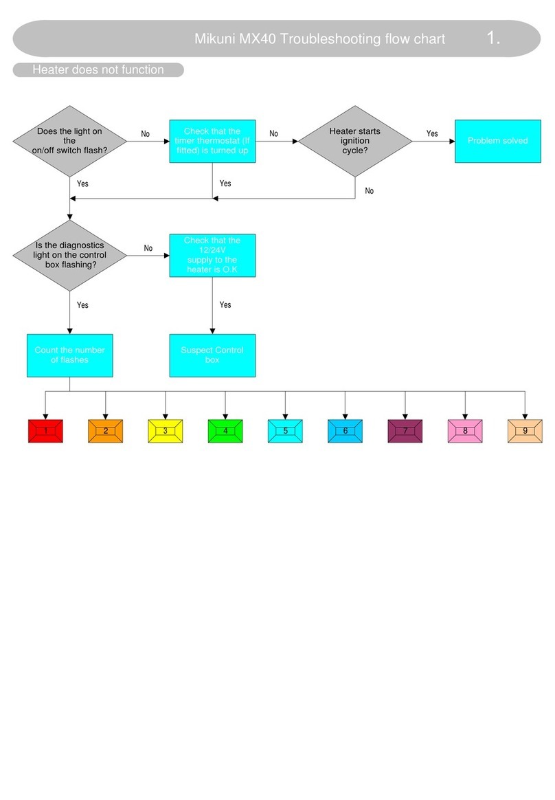
The MY16 heater is equipped with a self diagnostic fault finding system to aid repair should a fault occur. NOTE: Should any
part fail or if there is a loose connection then the control box will not allow the heater to start at all and a fault code should flash
in the control box window. The following table should assist you in repairing the heater if you follow the instructions step by
step. This list has been compiled from experience of the MY16 on the UK market. If you discover any new anomalies please
inform us so that we may add them to our list.
ON/OFF FREQUENCY
1.
2.
5.
6.
7.
8.
CAUSE
IGNITION FAILURE
NO FLAME SENSING.
MOTOR FAILURE
FUEL PUMP FAILURE
GLOW PLUG FAILURE
BATTERY VOLTAGE ABNORMAL
REMEDY-MOVE FROM POINT TO POINT IN ORDER UNTIL FAULT IS LOCATED
CHECK FUEL SUPPLY > FROZEN FUEL LINE? > CHECK AND CLEAN FILTER IN FUEL PUMP > CHECK FOR BLOCKED STANDPIPE > COMBUSTION AIR OR
EXHAUST PIPE BLOCKED OR DAMAGED? > IF HEATER RUNS OK FOR APPROX 3 MINS AND STOPS-SUSPECT FLAME SENSOR > IF HEATER SMOKES
BADLY AND STOPS AFTER 3 MINS STRIP DOWN AND DECOKE.
CHECK ALL PLUGS AND SOCKETS IN WIRING LOOM > LOOK AT FLAME SENSOR;IF THE SEALANT IS PUSHING OUT OF THE RETAINING NUT REPLACE
WITH A NEW FLAME SENSOR.IF NOT CHECK FOR BAD CONNECTIONS ON PCB INSIDE GLOW PLUG COVER > CHECK CONTROL BOX.
CHECK MOTOR FUSE 12V=7.5A 24V=5A > IF FAILED ENSURE THAT MOTOR SPINS FREELY > CHECK WIRING LOOM CONTINUITY > CHECK MOTOR >
CHECK CONTROL BOX > CHECK FOR BAD CONNECTION ON PCB INSIDE GLOW PLUG COVER.
CHECK CONTROL BOX > CHECK CONTINUITY OF WIRING LOOM AND INSPECT FUEL PUMP TERMINALS FOR CORROSION > CHECK CONTINUITY OF
FUEL PUMP.
CHECK GLOW PLUG FUSE=25A (IF APPLICABLE) > CHECK GLOW PLUG AND GLOW PLUG RESISTOR ON 24V MODELS. > CHECK CONTROL BOX > CHECK
WIRING LOOM. NOTE:THE GLOW PLUG RESISTOR IS A DIFFERENT PART TO THE GLOW PLUG -DO NOT INTERCHANGE! [24 VOLT ONLY].
THE HEATER WILL CUT OFF IF THE BATTERY VOLTAGE IS TO HIGH OR TO LOW.OPERATING RANGE FOR THE 12V MODEL IS 10.5 > 14VOLTS AND THE
24V MODEL IS 21 > 28 VOLTS.CHECK THE VOLTAGE AT THE HEATER WHILE IT IS RUNNING (SO THAT THE BATTERY IS UNDER LOAD) WITH THE BOAT
ENGINE OFF AND AGAIN WITH THE ENGINE RUNNING TO ENSURE THAT THE VOLTAGE IS WITHIN THE OPERATING RANGE OF THE HEATER.
9. OVERHEATING MAKE SURE THAT THE HEATER HAS COOLED DOWN AND CHECK THE MOTOR FUSE > CHECK THE AIR INLET AND THE HOT AIR OUTLET FOR
BLOCKAGETHE HOT AIR OUTLET FOR BLOCKAGE OR RESTRICTION. NOTE: OVERHEAT CUT-OUT WILL AUTOMATICALLY RE-SET WHEN THE HEATER
COOLS DOWN.
NOTES: (a)
(b)
(C)
IF THE HEATER FAILS TO START BUT THE DIAGNOSTIC IS NOT FLASHING-CHECK THE THERMOSTAT BY LINKING THE TWO RED WIRES TOGETHER.
ON INTIAL OPERATION OR IF THE VEHICLE HAS RUN OUT OF FUELTHE SYSTEM WILL NEED TO BE RE-PRIMED.THIS SHOULD BE DONE BY PUSHING
FUEL THROUGH THE PUMP WITH A SYRINGE OR BY USING THE MIKUNI SP21 PRIMING PUMP.
IF THE GLOW PLUG FAILS, INSPECT THE BOSS FOR CARBON DEPOSIT OR STRAY STRANDS OF S/S GAUZE.CLEAN AS NECESSARY AND ENSURE THAT
THE GAUZE IS NOT BURNT OR DAMAGED.IF IT IS REPLACE THE GLOW PLUG BOSS ASSY.
MY16 Self Diagnostic Fault Finding System.
-
10
-

MY16 FAULT FINDING SEQUENCE
RED LIGHT ON
THE THERMOSTAT
FLASHES SLOWLY.
IS THE 12/24V
SUPPLY CORRECT? SUSPECT ELECTRONIC
CONTROL BOX.
DO YOU HAVE A
12/24V SUPPLY? IS THE MAIN
30A FUSE O.K?
CHECK FOR LOOSE CONNECTION
OR CORROSION OF TERMINALS
ON THE MAIN POWER FEED.
REPLACE!
HEATER MOTOR
STARTS
CHECK THE SELF DIAGNOSTIC
LAMP IN THE CONTROL BOX AND READ
NUMBER OF FLASHES.
IS THE LIGHT
FLASHING 5 TIMES?
REFER TO SEPERATE SHEET
DESCRIBING SELF DIAGNOSTICS.
IS THE MOTOR
FUSE BLOWN? CHECK MOTOR BY APPLYING
SUPPLY VOLTS DIRECTLY TO IT.REPLACE
MOTOR.
SUSPECT CONTROL BOX
AND CHECK CONTINUITY
OF WIRING LOOM.
REPLACE!
12V = 7.5A
24V = 5A .
IF THE MOTOR FUSE FAILS AGAIN
SUSPECT MOTOR. IF THE MOTOR RUNS
CONTINUOUSLY AT FULL SPEED FROM SWITCH
ON, CHANGE THE CONTROL BOX.
IF THE VOLTAGE IS LOW CHECK THE
VEHICLE BATTERIES OR CORROSION
OF TERMINALS ON THE MAIN BATTERY FEED.
IF THE FUSE BLOWS AGAIN CHECK THE
GLOW PLUG.IF IT IS COVERED WITH CARBON
CLEAN THOROUGHLY OR REPLACE.
IS THE GREEN LIGHT
ON THE THERMOSTAT
ILLUMINATED?
TURN UP
THE DIAL
ON STAT.
SWITCH
ON
FUEL PUMP STARTS
15 SECS AFTER SWITCH ON. SUSPECT FUEL PUMP OR
BLOCKAGE IN FUEL LINE.
HEATER IGNITES AND
CONTINUES TO RUN
DOES THE HEATER EMIT
WHITE SMOKE FROM
THE EXHAUST
CHECK THE FUEL SUPPLY
AND ALSO FOR FOULING OF
THE GLOW PLUG.
DOES THE HEATER RUN FOR
ABOUT 3 MINS AND STOP? IF THE HEATER EMITS WHITE SMOKE AND POPS
THEN IT WILL REQUIRE DISMANTLING AND CLEANING
SUSPECT FLAME SENSOR-
REPLACE!
OVERHEAT THERMOSTAT
IS ACTIVATED
1.CHECK AIR INLET FILTER
2.CHECK FOR DAMAGED DUCTING
3.CHECK FOR BLOCKAGE OF AIR OUTLET GRILL
4.SUSPECT OVERHEAT THERMOSTAT.
AFTER 2 MINS COOL DOWN
CYCLE THE HEATER STOPS
TEST COMPLETE!
SUSPECT CONTROL BOX
OR ON/OFF SWITCH FAILURE
SWITCH OFF
NO
NO
NO
NO
NO
NO
NO
NO
NO
NO NO
NO
YES
YES
YES
YES
YES
YES
YES
YES
YES
YES
YES
NO
NO GO.
O.K.
-
11
-

SWITCH ON
MOTOR STARTS CHECK 12V SUPPLY DOES FUEL PUMP START
AFTER 40 SECONDS? CHECK MOTOR
FUSE SUSPECT MOTOR
30 AMP FUSE
BLOWN? CHECK OVERHEAT
CUT-OUTS REPLACE WITH 10 AMP
SLOW BLOW TYPE.
IF THE TOP TRIP HAS FAILED
THE SUPPLY HAS PROBABLY
BEEN CUT WHILST THE HEATER
IS RUNNING-RESET!
IF THE NOSE CONE TRIP HAS
FAILED CHECK FOR RESTRICTION
IN AIR FLOW i.e:BLOCKED INLET
FILTER OR OBSTACLE IN FRONT
OF HOT AIR OUTLET.
SUSPECT CONTROL
BOX REPLACE
CHECK FOR SHORT
OR FOULING OF
GLOW PLUG
CLEAN OR IF COILS
ARE DAMAGED-REPLACE!
HEATER RUNS COLD
FOR APPROX 3 MINS
AND THEN STOPS
NO
YES
NO
O.K.
YES YES O.K.
FAILED
NO
O.K.
FAILED
YES
NO
MIKUNI MY30 FAULT FINDING SEQUENCE.
HEATER RUNS HOT
FOR APPROX 3 MINS
AND THEN STOPS
CHECK FIRING CONTROL
(FLAME SENSOR) INSUFFICIENT FUEL
SUPPLY AIR LEAKS
IN FUEL PIPE REPAIR!
REPLACE!
CHECK COMBUSTION AIR
INLET & EXHAUST FOR
BLOCKAGE OR DAMAGE
FUEL RESTRICTION.
CHECK:
1.FUEL FILTER
2.TANK STANDPIPE
3.FUEL PUMP.
OVERHEAT CUT-OUTS
TRIP AFTER A FEW
MINUTES.
CHECK FOR RESTRICTED
AIR FLOW. REMOVE OBSTACLE OR
CLEAN AIR INLET FILTER.
HEATER WILL REQUIRE
SERVICING
SWITCH OFF
DOES HEATER CONTINUE
WITH A 2 MINUTE COOL
DOWN CYCLE?
SUSPECT FIRING CONTROL
(FLAME SENSOR) REPLACE!
TEST COMPLETE
O.K.
YES
YES YES
YES
YES
YES
YES YES
O.K.
FAILED
NO
NO NO
NO
NO
CHECK GLOW PLUG REPLACE AND CHECK
FOR CARBON IN G.P. BOSS
CHECK VOLTAGE ON
GLOW PLUG. SUSPECT WIRING OR
CONTROL BOX
SUSPECT FUEL SUPPLY
CHECK:
1.DAMAGED FUEL LINES
2.AIR LOCK IN FUEL PUMP
3.FUEL PUMP OPERATION
FAILED
O.K.
ZERO
O.K.
NO
-
12
-

-
13
-
Mikuni MY Series Marine Installation Manual
.
Part No
:
MY
30
Marine ins
-
NT
.
9
th Edition
:
Sep
2006
Mikuni Heating
(
UK
)
Ltd
Unit
6
& 7
,
Second Avenue Business Park
,
Millbrook
,
Southampton
,
SO
15 0
LP
.
Tel
:
023 8052 8777
.
Fax
:
023 8052 8808
.
Specifications
,
designs
,
etc in this manual are subject to change without prior notice
.
All rights reserved
.
No reproduction or reprinting are allowed
without our consent
.
This manual suits for next models
2
Table of contents
Other Mikuni Heater manuals
Popular Heater manuals by other brands

Trotec
Trotec TIH 300 S operating manual
Ozeanos
Ozeanos OT-FH-2000T instruction manual
STIEBEL ELTRON
STIEBEL ELTRON Eltronom SHU 5 S Operating and installation instructions
Empire Comfort Systems
Empire Comfort Systems RH-50-6 Installation instructions and owner's manual
Broan
Broan 114 owner's manual
HJM
HJM 624 Using instructions
