Milennia HV-316 User manual
HV-316 Remote Control
Microphone Preamplifier
Owner’s Manual

Millennia Media HV-316 page 2 of 17
Table of Contents
INTRODUCTION........................... 3
SAFETY PRECAUTIONS ................ 3
FRONT PANEL FUNCTIONS .......... 5
1. Unit ID Display .......................................5
2. Power Indicator ......................................5
3. Input Level & Phantom Power Indicator .....5
4. Auxiliary Power ......................................5
5. Power Switch .........................................5
REAR PANEL FUNCTIONS ............ 5
1. AC Power...............................................5
2. MIDI Connection.....................................5
3. Ethernet ................................................5
4. Network Reset........................................5
5. 12 Volt Redundant (Auxiliary) Power .........5
6. Unit ID Selector......................................5
7. Mic Inputs..............................................5
8. Analog Output Option..............................5
9. Reserved DB25.......................................5
GETTING STARTED ...................... 6
Installing the Ælogic Software ..........................6
Setting Unit ID(s) and IP Addresses ..................7
Setting the Host Computer’s IP Address (Windows
10)................................................................7
Dynamic Host Configuration Protocol (DHCP)......8
Default Settings ..............................................8
ÆLOGIC OPERATION ................... 9
Unit Status Window.........................................9
Red Icon ........................................................9
Green Icon .....................................................9
Flashing Green Icon ........................................9
Purple Icon.....................................................9
Blue Icon .......................................................9
Gray Icon.......................................................9
Unit ID Conflict ...............................................9
Unit Status Dialog ...........................................9
Overview .....................................................10
Control Section ..........................................10
Control Layout ...........................................10
Unit Naming and Unit Name Dialog Box ...........11
POLarity Flip................................................. 11
PAD.............................................................11
48V .............................................................11
MUTE...........................................................11
Channel Gain Faders/Gain Display...................11
Meter Preferences Dialog ...............................11
SPLIT ..........................................................11
SAFE ...........................................................11
RBN ............................................................11
HPF .............................................................11
Link Assignment ...........................................12
Scribble Strip................................................12
Link Matrix .................................................12
Scene Window ...........................................13
Project and Scene Management .................13
Creating a Project .........................................13
Scene Window.............................................. 13
Safety Prompts ............................................ 13
Creating New Scenes .................................... 13
Renaming Scenes ......................................... 13
Reordering Scenes........................................ 13
Recalling Scenes........................................... 13
Deleting Scene ............................................. 14
Locking Scene Window Functions.................... 14
Appending and Saving Scenes........................ 14
Saving Scene Changes .................................. 14
Loss of Power............................................... 14
Setup Menu ................................................. 14
Diagnostics .................................................. 14
Setup System Status .................................... 14
Soft Reset ................................................... 14
Restart Program ........................................... 14
APPENDIX ................................. 15
Ælogic Keyboard Shortcuts ............................ 15
Microphone input wiring diagram .................... 15
SPECIFICATIONS ...................... 16
ARCHITECTS AND ENGINEERS
SPECIFICATION ........................ 17
WARRANTY ............................... 17

Page 3 of 17 rev 103020 Millennia Media HV-316
Introduction
Congratulations on your purchase of the Millennia
Media HV-316 Remote-Controllable Microphone
Preamplifier.
We will refer to both the HV-316/8 8-Channel
and HV-316 16-Channel as the HV-316 unless
there is an operational difference.
The HV-316 is the result of meticulous blind listening
tests on innumerable circuit topologies and E/M
designs. Your HV-316 is a finely tuned instrument
intended for critical professional applications —we
feel it offers the world's most sonically neutral
microphone preamplification.
Up to 16 HV-316s can be simultaneously controlled
plus an additional 16 HV-3Rs –a total of 384
channels on one system. A high-speed Ethernet
control interface makes this possible without any
significant system control latency, even if all 384
channels were to change parameters simultaneously.
Future Update: The MIDI control interface is
compatible with Avid’s Pro Tools®“PRE” remote
microphone preamplifier protocol. As defined by
Avid, up to 4 HV-316 (8 HV-316/8) units can be
simultaneously controlled with MIDI in Pro Tools.
FCC Notice Information for the User
This equipment has been tested and found to comply
with the limits for a Class A digital device, pursuant
to part 15 of the FCC Rules. These limits are
designed to provide reasonable protection against
harmful interference when the equipment is operated
in a commercial environment. This equipment
generates, uses, and can radiate radio frequency
energy and, if not installed and used in accordance
with this instruction manual, may cause harmful
interference to radio communications. Operation of
this equipment in a residential area is likely to cause
harmful interference in which case the user will be
required to correct the interference at his or her own
expense.
Safety Precautions
For your safety and the safety of others, be sure to
read and understand all safety and operational
instructions before attempting to use the HV-316.
WARNING: The HV-316 internal circuitry carries
lethal voltages. Carefully observe all warnings,
precautions, and instructions on the HV-316 and as
described in the instructions supplied with the unit.
Water, Moisture, and Spillage –Do not attempt
to use the HV-316 in, near, or around water or in
unusually moist environments, such as near a sink or
swimming pool. Prevent liquids or any other
materials or objects from spilling or falling into the
HV-316 unit.
Heat & Ventilation –Be sure to allow adequate
ventilation on both sides of the HV-316 and avoid
blocking the fan air intake and exit vents.
Power Sources & Power Cord Protection –The
HV-316 Power Supply should be connected to a
power source only of the type described in the
operating instructions or as marked on the Power
Supply. Route the power cord so that it is not likely
to be walked on or pinched by having objects placed
on it. Pay particular attention to plugs, receptacles,
and the point where the AC power cord exits the
HV-316.
Grounding –For your safety, it is extremely
important that the grounding pin of the 3-wire power
cable (included with 110 Volt units) be inserted into
a grounding type 3-pin power outlet. If you are
unable to insert the plug into an existing outlet,
contact an electrician to install a properly grounded
3-pin power outlet, preferably that with OFI / GFI
protection, if available.
Damage Requiring Service –This unit should be
repaired or serviced by qualified personnel
whenever:
•The AC power cord has been damaged, or
•Objects have fallen or liquid has spilled into
any HV-316 unit, or
•The unit does not function properly or
exhibits a marked change in performance,
or
•The unit has been abused, dropped, or
damaged, or
•The unit has been exposed to rain or
moisture.
Servicing –Lethal voltages are found inside the
HV-316 chassis. The user should not attempt to
repair or service this unit. All servicing and/or repairs
should be referred to Millennia.
If, after reading all instructions, precautions, and
warnings, you have remaining questions, please
contact Millennia directly before attempting to use
your HV-316.
The HV-316 enclosure measures approximately 17”
wide x 1.75” high x 16” deep and is designed for
mounting into a standard 1U, 19” equipment rack. If
the HV-316 is mounted in a road case or other rack
which is prone to strong vibration or shock, it is
highly recommended that the rear of the HV-316 be
supported or otherwise reinforced to withstand such
conditions.
HV-316 is designed on a common ground topology.
For high quality operation, and for your own safety
and the safety of others, do not defeat the power
cord earth grounding pin.

Millennia Media HV-316 page 4 of 17
HV-316 Front-End Protection –Millennia Music &
Media Systems enjoys a reputation for what many
top engineers and producers call the world’s most
musically accurate and dynamically uniform
microphone preamplifier —the HV-3. But this
thoroughbred design is not achieved without certain
operating criteria. To maintain top performance and
protect the HV-316’s sensitive HV-3 front-end, it is
advised that you do not insert or extract
microphones with phantom power on. Get in the
habit of waiting about ten seconds for the phantom
power to fully “ramp down” before inserting or
removing a microphone. This is good advice for
protecting your microphone investments, as well.
Any changes or modifications not expressly approved
by MILLENNIA MEDIA, FPC (Millennia) could void
your authority to operate this equipment under the
EC, ICAN, or FCC rules.
Copyright –You acknowledge that no title to the
intellectual property in the HV-316 is transferred to
you.
Inspection –Inspect packing box(es), HV-316, and
cable(s) for damage, unusual marks, or shortages. It
is your responsibility to report damage, shortage, or
mis-shipments in a timely manner. Millennia and/or
its dealers will not be responsible for claims arising
from damage in shipping, nor will claims for shortage
or mis-shipments be honored, more than 10 days
after ship date.
Read this manual carefully and completely before
attempting to use the HV-316. Improper operation
could result in damage to product. It is the user’s
responsibility to understand the safe use and
operation of this device.
The shipping box of the HV-316 system will include:
•Quick Start Guide
•UL approved power cord (110 V countries only
except Japan)
The material contained in this manual consists of
information that is property of Millennia and is
intended solely for use by the purchasers of the
equipment described in this manual. Without express
written permission, Millennia prohibits the duplication
of any portion of this manual or the use thereof for
any purpose other than the operation and/or
maintenance of the equipment described in this
manual. This manual may not be duplicated in whole
or in part without the written consent of Millennia.
The HV-316 serial number is located on the rear and
bottom of each unit. We suggest that you record the
serial number in the space provided below. Refer to
it whenever you call an authorized Millennia repair
facility or the manufacturer. Make sure that you
register your Millennia product(s) online.
Features and specifications subject to change
without notice.
© 2020 –Millennia Media, FPC., all rights reserved
Serial Number
__________________________________________
Purchase Date
__________________________________________
Where Purchased
__________________________________________
Page 5 of 17 rev 103020 Millennia Media HV-316
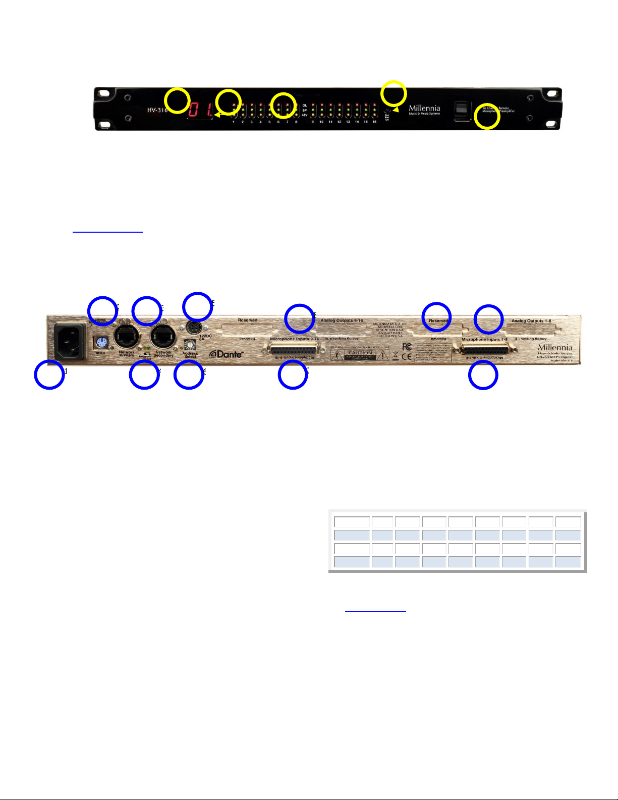
Front Panel Functions
The 3/8” thick hand-machined aluminum front panel
consists of 48 LED status indicators and a two-digit
numerical display.
Ælogic software is required to operate the HV-316.
The most current version can be downloaded at
Ælogic Weblink. Scroll down to the Downloads
section. It requires a computer running MS Windows
10 or higher.
1. Unit ID Display –Indicates unit number assigned
to preamp.
2. Power Indicator –Decimal point indicates unit
has power. It takes about 20 seconds after
power up before the Unit ID Display comes on.
3. Input Level & Phantom Power Indicator –
Green indicates levels -46 dBFS and higher. Red
indicates 0 dBFS. Amber indicates phantom
power is on.
4. Auxiliary Power –Indicates 12V auxiliary
(redundant) power source is powering unit.
5. Power Switch –Turns the unit on and off.
Rear Panel Functions
1. AC Power –IEC power inlet, 80-264 VAC 47-63 Hz
2. MIDI Connection –Allows remote control of the
HV-316 using MIDI protocol. Use with Yamaha
break-out cable ZP893500
3. Ethernet –Dante audio networking and Ælogic
control. Ælogic is only available on the Network
Primary connector
4. Network Reset –Restore to factory default
settings. Static IP address 192.168.1.221, Netmask
255.255.255.0
HV316 must be powered off.
Insert a small non-metallic object into the reset
opening on the read of the unit. You should feel a
slight click when the reset button is depressed.
Turn on the unit while continuing to hold the reset
button.
When the unit processor has reset it will display “00”
in the Unit ID display on the front of the unit.
Release the reset switch on the rear. The unit will
continue to boot.
When the ID Display switches to the selected Unit
ID, the device is ready to use. It will have the factory
profile and will be set to Static IP address
192.168.1.221, Netmask 255.255.255.0.
5. 12 Volt Redundant (Auxiliary) Power –
Connect only Millennia approved optional backup
power supply here.
6. Unit ID Selector –Address Select Rotary
Switch sets Unit ID. The front panel numeric
display changes to reflect the value selected
here. If connected to a network, the power
needs to be cycled for the change to take effect
in Ælogic.
7. Mic Inputs –Eight channels of
microphone-level input wired in the AES59/
Tascam format.
8. Analog Output Option –DB25s wired in the
AES59/Tascam format for analog outputs. This
option must be added at the factory.
9. Reserved DB25 –for future options.
Address
1
2
3
4
5
6
7
8
Unit ID
1
2
3
4
5
6
7
8
Address
9
A
B
C
D
E
F
0
Unit ID
9
10
11
12
13
14
15
16
2
1
3
5
3
4
1
5
2
4
2
3
1
5
6
8
7
5
2
3
8
9
9
1
4
6
7
7
8
Millennia Media HV-316 page 6 of 17
Getting Started
Millennia’s Ælogic software (Windows 10 only, other
versions may work but are not supported) is used to
control the unit and should be installed on your
computer before connecting the HV-316 to the
network. It can be downloaded at Ælogic Software
Scroll down to the Downloads section.
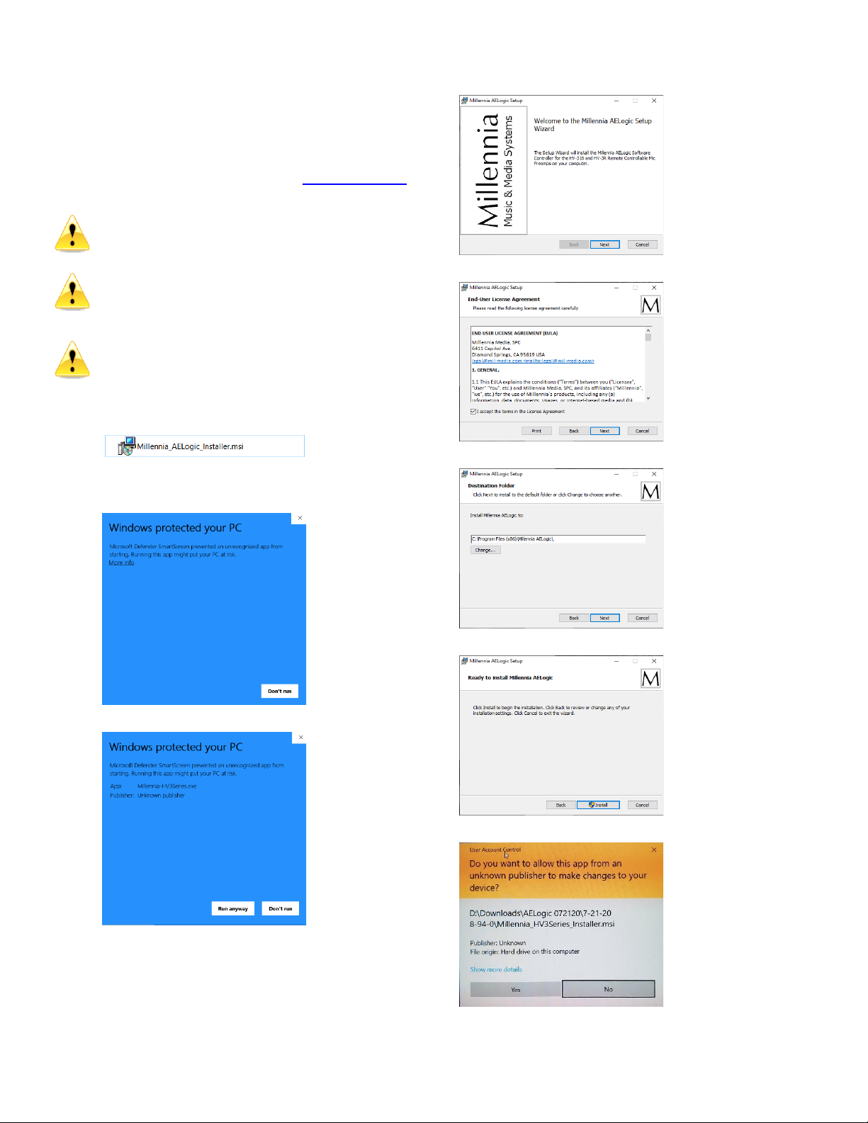
Installing the Ælogic Software –Turn off virus
protection software before installing. Remember to
turn the protection software on when finished.
You need to allow Ælogic all permissions to access
your network. Failing to do so will prevent the
software from seeing the Millennia Preamps
connected.
If you are using Wi-Fi®, turn it off and use the wired
Ethernet connection to be sure all the permissions
are applied to it so you connect the HV-316 directly
to your computer to initialize its IP address.
Extract the zipped files and Open
The following screen will appear.
Click on more info.
Click on Run Anyway
Click on Next
Check Accept and click on Next
Select the location to save the file and click Next
Click on Install
Click on Yes
Page 7 of 17 rev 103020 Millennia Media HV-316
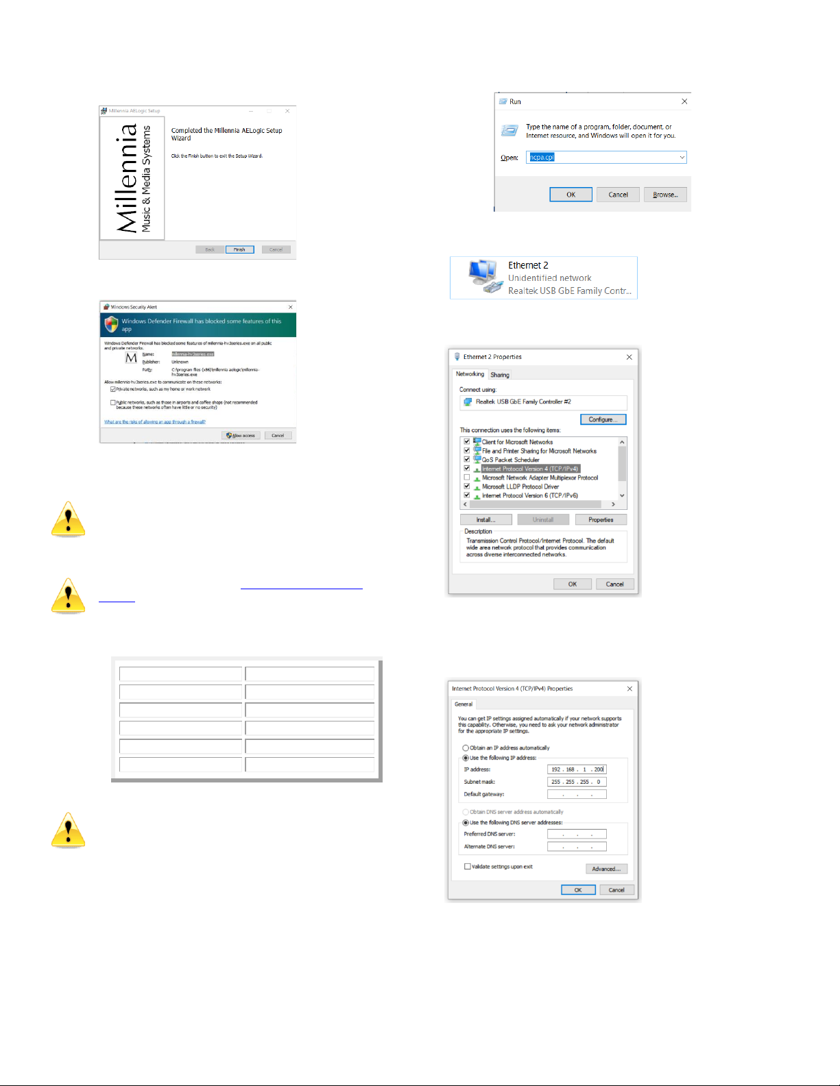
Click on Finish
Select Private Network and Click on Allow Access
Setting Unit ID(s) and IP Addresses –Each
HV-316 needs to be set to its own unique Unit ID
and IP address. If units have the same ID or IP
addresses there will be a conflict and the system will
not work properly.
Set the Unit ID using the Address Select Rotary
Switch on the rear panel before connecting the HV-
316 to the computer or network.
The table below is a suggested addressing scheme.
IP Address
Unit ID
192.168.1.200
Host Computer
192.168.1.221
HV-316 ID 01
192.168.1.222
HV-316 ID 02
192.168.1.223
HV-316 ID 03
192.168.1.2nn
HV-316 ID nn
Be sure the computer’s wired Ethernet connection is
set to IP address 192.168.1.200.
There are many ways to do this and Microsoft
occasionally changes the setup menus. As of this
writing, this method allows quick IP address setting.
Setting the Host Computer’s IP Address
(Windows 10)
1. Press the Windows key and the Rkey at
the same time to open the Run box.
Type ncpa.cpl and press Enter to access
Network Connections immediately.
2. Double click on the HV-316 Ethernet Connection
to open its properties.
3. Double Click on Internet Protocol Version 4
(TCL/IPv4)
4. Select “Use the following IP addresses”.
5. Enter 192.168.1.200 in IP Address.
6. Enter 255.255.255.0 in Subnet mask.
7. Click OK and continue to exit Network
Connections.
8. Connect the Host Computer directly to the
HV-316’s Ethernet Port
9. Run the Ælogic Software.
Millennia Media HV-316 page 8 of 17
If you have everything set correctly when Ælogic
opens, the icon of the HV-316’s Unit ID in the Unit
Status window will turn green. Double click on it to
open the Unit Status dialog box.
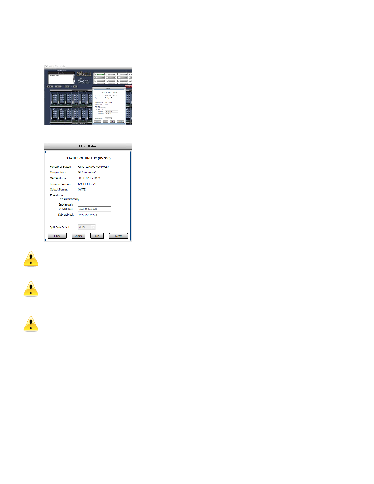
Set the HV-316 IP address and click OK
You will lose connection if you select an IP
Address other than 192.168.1.xxx and will need
to change your computer’s IP Address to access the
network that you have chosen to use your HV-316s.
Dynamic Host Configuration Protocol (DHCP) is
also an option for “IP Address”, but we don’t
recommend using it unless you are familiar with
networking and have the proper network hardware
that supports it.
Ethernet and MIDI control cannot be used
simultaneously –only one remote control protocol
can be used in an HV-316 network.
Default Settings –The HV-316 is shipped to
startup with the default settings:
•All functions turned off (POL, PAD, 48V,
MUTE, SPLIT, SAFE, RBN and HPF).
•IP Address set to 192.168.1.221
•Netmask 255.255.255.0
•Unit ID 1
Page 9 of 17 rev 103020 Millennia Media HV-316
Ælogic Operation
Millennia’s Ælogic remote control software is
intuitive. What follows is an in-depth description of
its available functions. Refer to Appendix for a list of
keyboard shortcuts.
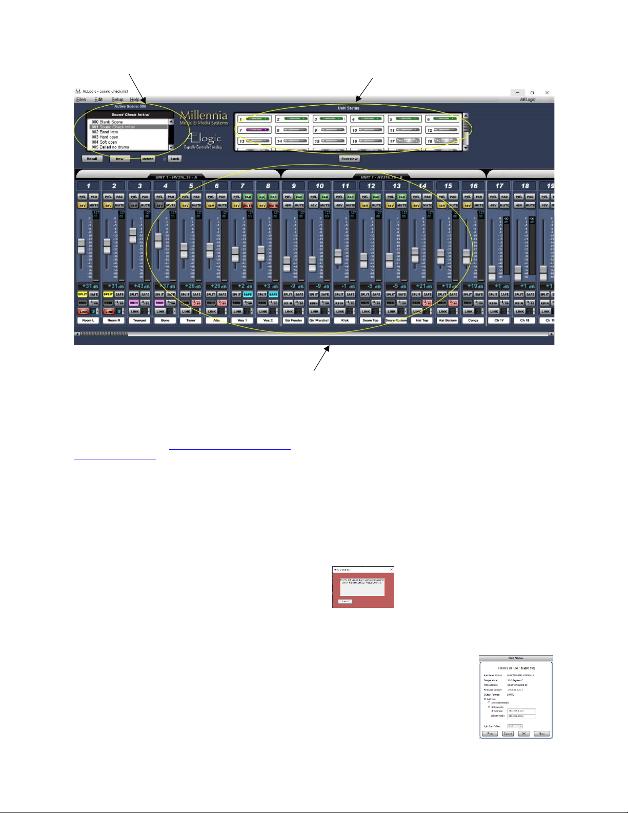
Unit Status Window –The example screen above
shows a Unit Status window in which seven HV-316
units (112 channels) are connected to the remote
network. The Unit Status window displays an icon of
each HV-316 unit on the network. The status of each
HV-316 is represented by its icon’s color code, as
follows:
Red Icon –“Unit ID Has a Conflict with Another
Unit”. If two or more HV-316s share the same Unit
ID number or IP address, their icons will turn red
and will show identical IDs or IP addresses until the
conflict is resolved.
Setting a Unit ID or IP address must be done locally
on each HV-316. Other errors could also cause a red
icon, such as over-temperature, power supply out of
range, other networking errors, etc.
Green Icon –“Functioning Normally”. Remote unit
functioning normally.
Flashing Green Icon –HV-3R only. “Functioning
Normally, Local Mode”. Remote unit is functioning
normally but is in the local mode.
HV-3R only: if the unit is in Local mode when Ælogic
is started, it won’t appear. Be sure to change the
unit to Remote mode so the software can recognize
the HV-3R.
Purple Icon –“Unit ID Is Offline”. A unit was
previously connected to the network and set to this
Unit ID but is missing from the network. It was
either turned off or the Ethernet was disconnected or
both.
Blue Icon –The Redundant Power Supply is
powering the unit and the internal power supply is
offline due to either failing or losing AC mains power.
Gray Icon –“Unit ID Is Inactive”. No unit is
connected to the network and set to this Unit ID.
Unit ID Conflict –If more than one unit has the
same ID number this warning will
appear. You must correct the
problem before you can continue.
Unit Status Dialog –Double left mouse click on
any icon brings up that unit’s Unit Status dialog box
displaying the following information:
1. Unit Functionality
2. 48v Monitor (HV-3R)
3. 24v Monitor (HV-3R)
4. 5v Monitor (HV-3R)
5. 3.3v Monitor (HV-3R)
6. Temperature
7. MAC Address
8. Firmware Version
9. Output Format
10. IP Address
11. Split Gain Offset
Scene Window
Unit Status Window
Control Section
Millennia Media HV-316 page 10 of 17
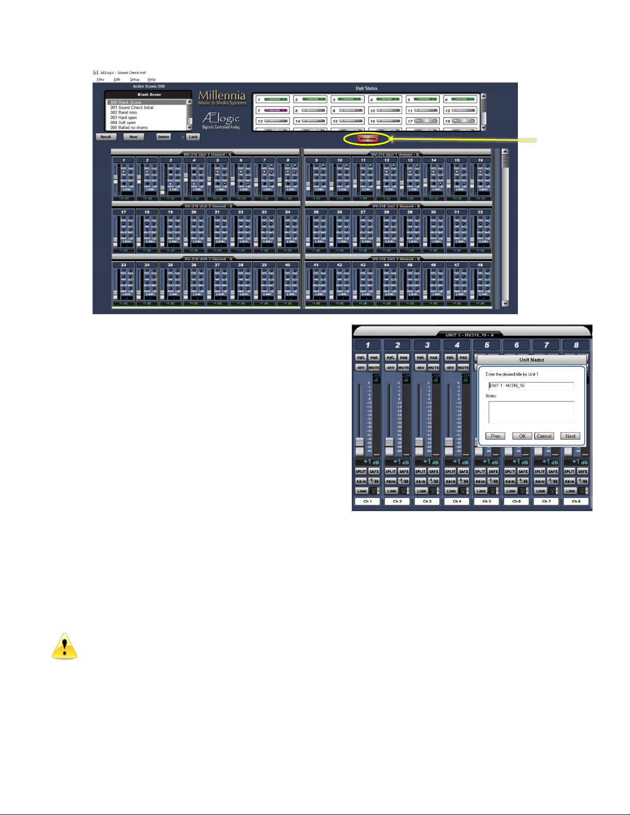
Overview –This is the default view. It expands
the channel control area to show multiple units.
Virtual switches are replaced by small virtual
LEDs. Link switch is replaced by link group
number only. Other attributes are shrunk to fit.
All functions remain accessible and adjustable
on the Overview Screen.
Above is a screen-shot of the OVERVIEW.
Control Section
Basic Navigation & Behavior
The channel controls are grouped into their
respective HV-316 8-channel Units. The screen
shot on the previous page shows units #1
through #7. You can left-click on any unit icon
shown in the Unit Status window to immediately
bring that unit’s channel controls into the main
screen.
Note the scroll bar at the bottom of the screen.
It allows the user to quickly scroll to any unit in
the network. You can also move the Control
Section by using the Left and Right arrow keys
on the keyboard. Pressing an arrow key once
corresponds to scrolling in that direction by one
channel strip.
HV-3R only: Ælogic is always the master control
when the unit is in Remote Mode. Any changes
made to the unit’s front panel in Local mode will
be overwritten when the HV-3R is put back into
Remote Mode.
Control Layout
The main control section, starting from the top
down, graphically represents these features:
1. Unit Name
2. Channel Number
3. Polarity Invert Button
4. Pad (20 dB Attenuator) Select Button
5. 48V Phantom Select Button
6. Mute Select Button
7. Gain fader
8. Plasma-type Metering
9. Channel Gain numeric
10. Split Gain Mode
11. Safe
12. Ribbon
13. High Pass Filter
14. Link Assignment
15. Scribble Strip
Overview

Page 11 of 17 rev 103020 Millennia Media HV-316
Unit Naming and Unit Name Dialog Box
(right-click on unit name) –Each Unit’s name is
shown above its eight-channel grouping. The default
name for each unit is its Unit ID. For instance, “UNIT
1”corresponds with channels 1-16 and “UNIT 2”
corresponds with channels 17-32. Right-clicking on
the Unit Name area opens the Unit Name dialog
(shown above) which allows textual naming of that
unit. A section for notes is also available to include
any supplementary information about the unit.
In order to name multiple units quickly, the “Prev”
and “Next” buttons allow the user to scroll through
units without closing the dialog box. If a unit has
been re-named from the default, the new Unit Name
will now be displayed in the Unit Name box. The
Naming Window can also be accessed from the
pull-down menus (Edit>Unit Naming).
Channel Strip Display and Functions
Channel Number –Channel numbers appear at the
top of the channel strip.
The preamp (HV-316) with Unit ID 1 will be assigned
channels 1-16. Unit ID 2 will be assigned channels
17-32 etc. The HV-316/8 and HV-3R are assigned 8
channels. Each HV-316 8-ch group is assigned “A” or
“B”.
POLarity Flip –Inverts channel audio output polarity
(180 degrees). The channel’s output waveform
becomes a mirror of the input signal. This is not a
“phase adjustment” as the output signal does not
shift in time relative to the input signal. Button
illuminates green.
PAD –Attenuates channel output by 20 dB (14 dB
HV-3R).The gain setting reflects the change.
Button illuminates green.
48V –Applies 48-volt phantom power to the
respective mic input channel. Phantom power is
applied equally to both pin 2 and pin 3 of that
channel’s mic input. Button illuminates yellow. You
must disable RBN before 48V can be enabled.
Caution –do not insert or extract a mic with
the phantom power on. It can damage the
microphone and/or the preamp input
MUTE –Mutes channel output. When channel is
muted, the meter will continue to operate allowing
the user to view audio activity on that channel
without passing live audio. Mute parameter is
linkable. Button illuminates red.
Channel Gain Faders/Gain Display –A traditional
looking “mixer fader” that adjusts preamp channel
gain. A text box below the fader indicates the actual
channel gain setting in decibels.
HV-316 gain range is 1 dB to 64 dB (HV-3R gain
range is 8 dB to 69 dB with 80 dB optional). Gain is
segmented in 1 dB steps. The Up and Down
keyboard arrow keys can also be used to adjust the
channel gain in 1dB steps.
Meter Preferences Dialog –The Meter Preferences
dialog box provides for customization of meter
display and functions.
You can select Meter Scale as dBu (usually for an
analog system) or dBFS, typically for digital systems.
Peak Hold Time affects the numerical level
indicator above the meter and the floating line over
it.
SPLIT –Future update: For the HV-316/8 and HV-
316 only. Provides two Dante outputs per channel,
this turns on the split’s gain compensation to provide
an inverted (constant) level (within +/- 12dB) of the
channel. Typically used to split signals between FOH
console and stage monitor console.
SAFE –The channel is not modified when a new
scene is loaded. All settings remain as they
currently are.
RBN –Turns off the 48V phantom power and DC-
couples the mic to the gain stage. Use with any
Ribbon or Dynamic mic (like an SM-57). A mic
requiring phantom power will not work in this mode.
You must disable 48V before RBN can be enabled.
HPF –High Pass Filter, when engaged, is -3dB
down at 80Hz, with 6 dB per octave roll off.
Millennia Media HV-316 page 12 of 17
Link Assignment –The Link parameter provides a
Gain and Mute linking utility. Linking applies to Gain
and Mute parameters only; no other parameters are
linkable.
The LINK button links and unlinks a channel from a
selected “link group”. There are ten selectable link
groups that can be chosen from the drop-down box
next to the LINK button or the Link Matrix. When a
link group is chosen, the LINK button is
automatically selected and illuminates red. One link
group can be assigned per channel. If no link group
is selected, a depressed LINK switch will effectively
do nothing.
Linked Gain –Linked Gain faders move together
maintaining the same distance they had when first
linked together. Once one fader reaches the upper or
lower extreme, the other faders in the same link
group stop moving in that direction.
Linked Gains can be trimmed by holding down the
Alt key while using the left mouse button. When the
Alt key is released, the channel reverts to linked
mode.
Linked Mute –Linked Mute parameters will turn on
and off together unless “Mute linked channels” is
unchecked in the Preferences dialog box (Setup>
Preferences>“Mute linked channels”). If this box is
unchecked, the mute parameters will act
independently just like the other parameters.
Scribble Strip –(right-click on scribble strip)
A text box in which channels can be named and
notes can be written and stored. See the screenshot
on the previous page.
To name multiple channels quickly, “Prev” and
“Next” buttons allow the user to scroll through
channels without closing the dialog box. If a channel
has been re-named from the default, the new
Channel Name will now be displayed in the Unit
Name box. The Naming Window can also be
accessed from the pull-down menus (Edit>Channel
Naming).
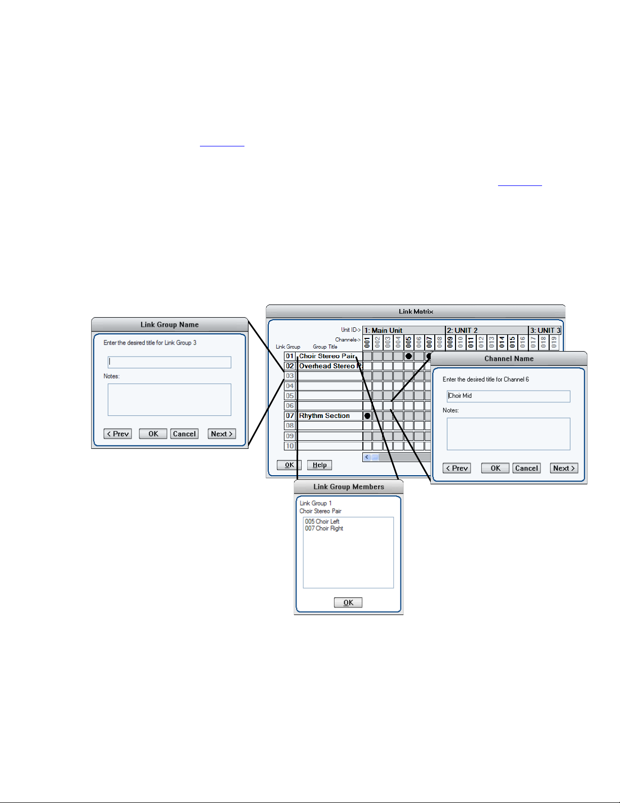
Link Matrix
The Link Matrix dialog box provides for easier linking
and unlinking of channels and can be accessed via
shortcut ctrl-L or from the pull-down menus
(Edit>Link).
•Name a Link Group by right clicking a Link
Group number.
•See the members of a group by double clicking
the group’s name.
•Right click a link to bring up the channel naming
dialog box.

Page 13 of 17 rev 103020 Millennia Media HV-316
Scene Window
The Scene Window is found in the upper left corner
of the screen. A Scene remembers and recalls all
parameters of the current software environment
(gains, mutes, links, etc.). Scenes are used for
applications such as concerts or stage plays in which
new acts or set changes require different microphone
gains, mutes, links, metering, etc.
There are a few physical aspects to the scene
window worth noting before creating new scenes and
projects:
“Active Scene: ###” –The active scene number
displays the number of the scene that is currently
active.
Scene Name Display –Just below the active scene
number is a text display that defaults to “Blank
Scene.” This area displays the user designated name
of the currently active scene.
“000 Blank Scene” –The default scene that is
automatically opened when the Ælogic is first loaded
or when a Project, New or Saved, is opened. The
Blank Scene is to be used as a null starting point.
Selecting scene 000 will force all parameters of all
networked units to their “off” or “lowest” settings.
This default scene cannot be overwritten.
The Scene List –Scenes are arranged sequentially
within the Scene Window (000, 001, 002, etc.). The
Scene List is a scrollable list of all Scenes within the
Scene Window. Left-clicking a Scene Number/Name
will highlight it. No system functions will change until
the Recall button is clicked or until the desired scene
is double-clicked.
Project and Scene Management
Creating a Project –Before anything (new scenes,
changes to scenes, etc.) can be saved, a project
itself must be created by doing a Save. Use
File>Save to name the Project and find a location to
save it. File>Save (ctrl-S) will save any updates or
changes to the project unless a new name is desired
(use File>Save As (shift+ctrl S)).
Scene Window –Underneath the Scene Window
there are four buttons “Recall”, “New”, “Delete”,
and “Lock.” The functions of these buttons are
explained below.
Safety Prompts –In order to exercise caution when
using the Scene Window Functions, safety prompts
are available in case buttons are pressed
accidentally. Safety prompts can be enabled for:
•New Scene
•Recall Scene
•Scene Delete
•Scene Re-Ordering
To turn safety prompts on and off go to
“Edit>Preferences” in the pull-down menus. The
section labeled “Scene Prompts” will have check
boxes for the four choices.
Creating New Scenes –Scenes are created by
using the “New” button below the scene window.
Once this button is pressed the “Enter Scene Name”
dialog box appears.
The scene name can be entered in the upper text
box and a section for Notes is also available to
include any supplementary information about the
scene. Once the scene is named it will be appended
to the Scene Window (next available scene number).
A newly created scene will assume all parameters
and settings of the active scene. Creating or naming
a scene does not make it active. Only Recall or
double-clicking can activate a scene.
Renaming Scenes –Once scenes are created, they
can be renamed by right-clicking on them. A dialog
box labeled “Rename Scene” will appear with the
same choices as the “Enter Scene Name” dialog box.
Reordering Scenes –Scenes are moved by
left-clicking and dragging them to the desired
location. Once a scene is moved, Ælogic will
automatically update the numbers in front of each
scene name.
Recalling Scenes –Scenes can be recalled two
different ways:
1. Highlight the desired scene and click the “Recall”
button.
2. Double click the scene name.
The scene’s parameters will be transmitted to all
of the units on the network.
Millennia Media HV-316 page 14 of 17
Scenes are not saved until you save the
project. (see Saving Scene Changes below for
information on how to save a scene)
Deleting Scenes –Scenes can also be deleted two
different ways: either highlighting the desired scene
and pressing the “Delete” button or highlighting it
and pressing the delete key on the keyboard.
Be careful when deleting scenes as the “Undo”
function does not work on deleted scenes.
When a scene is deleted, higher scene numbers will
automatically decrement. If an attempt to delete the
currently Active Scene is made, a prompt will pop up
explaining that it is active and cannot be deleted.
Locking Scene Window Functions –Sometimes it
may be necessary to disable the functions of the
Scene Window. The “Lock” button serves this
purpose. When the button is engaged, the other
three functions will turn dark grey and will no longer
be functional. Parameters in the Control Section
(faders, Links, function buttons, etc.) will still be
functional.
Appending and Saving Scenes –Whenever a
change is made to any parameter or function, an
asterisk (*) will appear next to the active scene in
the Scene Window (with the exception of the Blank
Scene). The asterisk will remain visible until the
Project is saved. The asterisk indicates a “dirty
event” – meaning that changes have been made
since the last Project save.
Saving Scene Changes –All Scenes shown in the
Scene Window are saved each time the Project is
saved (File>Save OR ctrl-S). Any changes to a
Scene (a “dirty event”) will be lost if the Project is
not saved before recalling another Project or if the
Project is not saved before exiting the GUI.
Loss of Power –If the HV-316 loses power or
ÆLogic crashes it will come back online with the
parameters set the same as when it went off except
parameters Link, Safe and Split will be off.
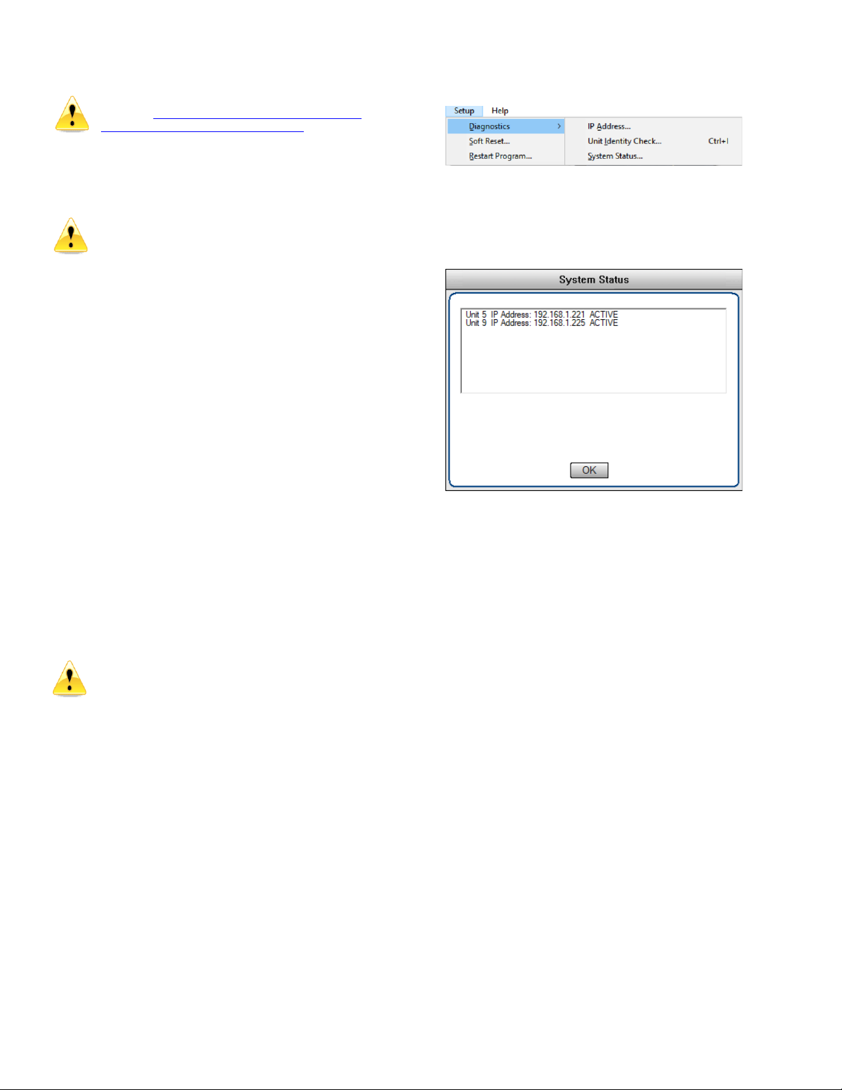
Setup Menu
Diagnostics –Check the IP Address, Flash the
display and shows the IP addresses and state of all
connected units
Setup System Status –shows the IP address and
state of all connected units
Soft Reset –Allows you to select a unit and reset it
to a state where all buttons are off and channel gain
is set to minimum.
Restart Program –Restarts ÆLogic

Page 15 of 17 rev 103020 Millennia Media HV-316
Appendix
Ælogic Keyboard Shortcuts
Keys
Function
Alt Click-and-Drag fader of linked group
Allows you to trim member of group
Alt E
Edit Menu
Alt F
File Menu
Alt F4
Close program
Alt S
Setup Menu
Click and Drag on Link Matrix
Drag across to link/unlink channels
Click and Drag POL or Pad or 48V or Mute
or Split or Safe or RBIN or HPF or Link
Drag across channel buttons to select or unselect
Click and Drag Scene name
Drag to new place in list
Ctrl H
Help Menu
Ctrl I
Unit identity check
Ctrl L
Brings up Link Matrix
Ctrl M
Meter preferences
Ctrl N
Create new project
Ctrl O
Open project
Ctrl S
Save
Ctrl Z
Undo (10 levels)
Double Click Group Title in Link Matrix
Lists channels that are members of the group
Double Click on unit icon in Unit Status box
Gives voltage, temperature and network data of
unit.
Double Click Scene name
Loads Scene
F1
Help Menu
Left/Right keys (on controls)
Move channels one over
Right Click Group title name in Link Matrix
Edit name
Right Click link box in Link Matrix
Edit channel name
Right Click on channel name below fader
Edit channel name
Right Click on meter
Edit meter settings
Right Click on unit name above faders
Edit unit name
Right Click scene name
Edit scene name
Shift Ctrl S
Save as
Up/Down keys (on controls)
Increment/Decrement gain by 1dB
Microphone input wiring diagram –DB-25 to XLR Female AES59/Tascam Format
Channel
1
2
3
4
5
6
7
8
+ Pins
24
10
21
7
18
4
15
1
–Pins
12
23
9
20
6
17
3
14
Gnd
Pins
25
11
22
8
19
5
16
2

Millennia Media HV-316 page 16 of 17
Specifications
Minimum Gain
1 dB
Maximum Gain (1 dB per step)
64 dB
Attenuator Pad
-20 dB
Frequency Response (analog output option) (+0 / -3 dB)
sub 3 Hz to beyond 300 kHz
Noise (60 dB Gain, 10 Hz - 30 kHz, Inputs common)
-130 dB EIN
Total Harmonic Distortion + Noise (35 dB Gain, 10 Hz - 20 kHz
bandwidth, 0 dBFS Out
< .005%, Typ.
Intermodulation Distortion (50 Hz & 7 kHz), 35 dB Gain, 0 dBFS
< .0009%
Phase Response (35 dB Gain, 50 Hz - 20 kHz bandwidth, 0 dBFS
< 2 degrees deviation
Common Mode Rejection Ratio (35 dB Gain, 10 Hz - 20 kHz
bandwidth, 100 mV C.M.)
> 65 dB, Typ > 85 dB
Slew Rate (35 dB Gain)
> 25 Volts per microsecond
Maximum Input Level (20 Hz - 40 kHz)
+34 dBu (pad in)
Maximum Output Level (20 Hz - 40 kHz) (analog output option)
+22 dBu (analog option)
Phantom Input Impedance (1 kHz)
6,750 ohms
Output Impedance
24.3 Ohms (analog option)
Phantom Powering
+48 V dc, +/- 2 V dc, 15 ma per channel
Power Consumption
100 watts maximum
AC: Universal 90-240V, 50/60 Hz
DC: 12V
Dimensions/Shipping Weight
19" W x 1.75" H x 16" D, 10 lbs (16ch), 9 lbs (8ch)
DANTE
Physical Layer
Ethernet
Connectors
Dual RJ-45
Cable Quality
CAT-5e or better
Transmission Speed
1Gbps
Supported Sample Rates
44.1kHz, 48kHz, 88.2kHz, 96kHz, 176.4kHz,
192kHz
Minimum Dante Latency
250 µS
Supported Modes
Redundant / Switched
AES67 Support
Planned
Certifications
FCC CFR 47 Part 15 Subpart B, Class A
ICES-03 Issue 6 (Canada)
ANSI C63.4-2014
Compliance
CE (EN55022 / EN55024)
RoHS 2002/95/EC
WEEE 2012/19/EU
REACH
Environmental
-10oto +65oC / +15oto +150oF
10% to 80% Relative Humidity
Millennia Media reserves the right to change specifications, delivery, and pricing without notice.

Page 17 of 17 rev 103020 Millennia Media HV-316
Architects and Engineers Specification
The Dante/AES67 interface will have 16 balanced mic/line
inputs available on DB-25 connectors.
The mic/line inputs for each channel will support up to 64dB
of digitally-controlled gain in 1dB increments.
Each input will have phantom powering available.
Each input will provide a selectable DC-coupled “ribbon mic”
path.
A DIN-type hardware MIDI control input will be provided.
A switchable attenuator will provide support for signal levels
up to +34dBu, when activated.
The front panel will include a power switch, along with display
that will show power active, aux power active, network unit
number, and LED status for each channel’s phantom, signal
present, and overload.
All mic/line input channels will have optional analog output
channels in addition to Dante output.
The device will support multiple digital-audio sample rates,
namely 44.1kHz, 48kHz, 88.2kHz, 96kHz, 176.4kHz, and
192kHz.
The device will have a 16-position rotary switch to select its
network ID number.
The device will have a reset button to restore all settings to
factory default.
The Dante interface will support a switched or redundant
network mode.
The device will have two integrated Gigabit Ethernet ports on
RJ-45 connectors.
The device will support Ethernet and power redundancy.
The device will operate from either 12 VDC power or 80-264
VAC power, 47 to 63 Hz.
All parameter settings shall be non-volatile and self-restoring
in the event of a power interruption.
The device will be compliant with FCC CFR47 Part 15 Class A,
ICES-03 Issue 6, ANSI 63.4-2014, CE EN55022 Class A and
EN 55024 Class A, RoHS 2002/95/EC, WEEE 2012/19/EU, and
REACH.
The device will be accompanied by Windows-based control
software called ÆLogic, offering visual access to hardware
control, functionality, and scene management.
The device shall be the Millennia HV-316.
Warranty
US and Canada: We will repair our products, free of charge,
in the event of defect of materials or workmanship for one (1)
year following date of purchase.
This limited warranty covers failures due only to defects in
materials and workmanship which occur during normal,
intended use and does not cover damage which occurs in
shipment or failures which are caused by products not
supplied by Millennia Media.
This limited warranty does not cover failures which arise from
accident, misuse, abuse, neglect, mishandling, misapplication,
faulty installation, improper adjustment, alteration or
modification of product, incompatibilities, line-power surges,
acts of God, or service performed by anyone other than
Millennia Media or its authorized agent.
Other Countries: In the event of defect of materials or
workmanship for two (2) years from the manufacturing date,
the authorized Millennia distributor will facilitate return of
product to our U.S. factory for repair.
This limited warranty covers failures due only to defects in
materials and workmanship which occur during normal,
intended use and does not cover damage which occurs in
shipment or failures which are caused by products not
supplied by Millennia Media.
This limited warranty does not cover failures which arise from
accident, misuse, abuse, neglect, mishandling, misapplication,
faulty installation, improper adjustment, alteration or
modification of product, incompatibilities, line-power surges,
acts of God, or service performed by anyone other than
Millennia Media or its authorized agent.
Shipping costs to/from factory are not covered under this
warranty. International warranty law may vary from country
to country, and Millennia will abide by the law of each
country.
This manual suits for next models
1
Table of contents
Other Milennia Amplifier manuals


