MN9000 Digital Lock Installation Steps
milesnelson.co.nz
2
1
4 5
INSTALL THE MORTISE LOCK FIRST
DOOR PREPERATION
INSTALL STRIKE PLATE
A selection of packers are supplied to suit dierent
aluminium joinery.
FIT BATTERIES SUPPLIED
Then follow programming instructions for lock operation
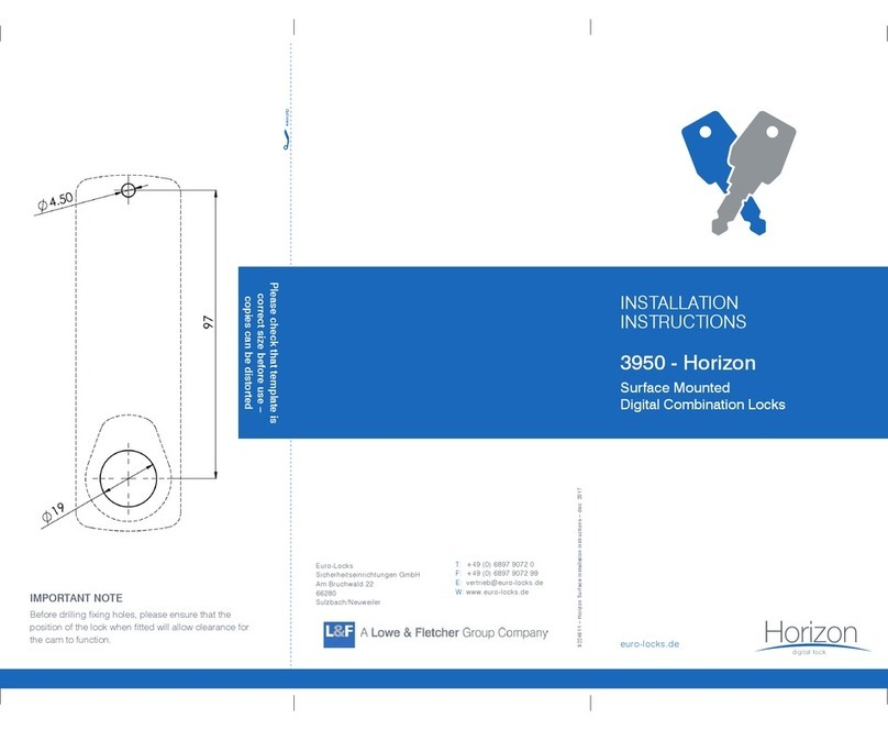
1. Mortise out a 95mm deep pocket (refer to the shaded section on
the template) for the latch body. You may use a 24mm drill bit
to remove most of the door material before you chisel out the
remaining material for the mortice lock.
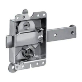
2. The Mortise lock body must be installed with the small security
bolt in the top position. Recess face flush with door edge.
3. We recommend you drill face holes from each side, meeting in
the middle.
1. Fold Template and place on door edge at desired height.
2. Mark square spindle height on middle of door edge (This will be the handle height).
3. Mark door face through holes on both sides of door.
Security bolt
3INSTALLING THE INTERIOR ASSEMBLY
WORK WITH THE DOOR OPEN FOR
EASY ACCESS
1. Unpack the interior unit first.
2. Remove the battery cover by sliding the cover upward.
3. Connect electronic cable between external and internal unit.
4. Ensure rubber gasket is aligned on interior / exterior units.
5. Fit the interior unit onto door and then fit exterior unit onto
door. Make sure the spindle from the interior unit is sitting
correctly in the cavity inside the exterior unit (to ensure
the lock will operate correctly). To test spindle is correctly
positioned, turn the inside handle downwards and both
handles should turn downwards together.
6. Screw the interior and exterior units together with the
supplied 19/16” screws, ensuring screws are tightened.
DO NOT OVER TIGHTEN.
7. Check that vertical alignment of the lock is correct.

