Mill-right 529 User manual

f 6r
r
- 0/ , ro-r'.,.,/llr'f
\qAEl.I/
/W^VU\U,
CAUTION!
Readall Safety
Instructions
Careful
ly
IKONWOODDKAND
MILL.RIGHT
ROUTER
MILLING CENTER
Designed,ManufacturedandSold
by: POSITIVE POSITION,INC.
SCHENECTADY.NY I2309
OWNER'S
MANTJAL
(Part
No :1t,B3052)
ModelNo.529
and
Accessories
Verli.Mill
B5018
Side.Mill
85041
Y-Posi.Mill85032
Extend.A.Mill
B5057
Spindle.N1ill
85071
Clamping
Kit85028
DovetailIndex85055
Dust
Collcctor
B5045
Convenience
Switch
85063

OWNER'SMANUAL
SAFETY
PRACTICESANDINSTRUCTIONS
I. GETTO
KNOWYOURMILL.RIGHT
Read
andunderstandyour owner's manualandthe
CAUTION! and WARNING! labels
in themanualand
affixed to thetool . Learnthe operationsandthe limitations
of theMILL.zuGHT as
well as
anypotential
hazardsthat
may
resultfrom itsoperation.
2. ROUTERSAFETY
Followthe
safety
practices
andinstructions
recommendedby
yourroutermanufacturer.
Ifyour routerrequires
grounding,
be
sure
to use
the
propergrounded
typereceptacle.
3. KEEPWORKAREACLEAN
Avoid accidentsby keeping
yourwork areaclutterfree.Do
notworkonwaxedfloorsor floorscovered
with sawdust.
4. AVOIDDANGEROUSCONDITIONS
Don'tuse
your
Mill.Rightindamporwetlocations.Use
adequate
lighting.
5. KEEP
CHILDRENSAFE
Donotoperate
with children
present.
Remove
starter
keys
whennot
inuse.
Lockworkshop
when
notinuse.
6. DON'TFORCETHETOOL
Do thejob better
and
safer
by operatingtherouterattherate
andspeedforwhichitwasdesigned.
Don'tforce
the
machinetodo
a
job itwasnot
designedfor.
7. CLOTHING
Donotwear
looseclothing,
gloves,
neckwearor
jewelry
which
can
get
caughtinmoving
machinery.Usenon-slip
shoes.
Containlong
hair.
Rolllongsleevesabovetheelbow.
8. USESAFETYGLASSES
Asaminimum,wear
safety
glasses
with
side
shieldsatall
times
(comply
with
ANSIZ'18.1).Usefaceordustmaskif
operation
warrants
and
ear
protection
during
extended
periods
ofoperation.
9. LNATTENDED
MACHINE
Neverleave
arunningmachineunattended.Be
sure
the
router
hascompletely
stoppedbefore
leaving.
IO.SECURE
WORK
Useclampsto secure
work towork surfaces.
When .. -.
movedfor operation,use
hold-downsor featherboa::r
againsttableand
guide
fence.When
possible.
freer:'-:
operatethemachine.
1I. DON'TOVERREACH
Maintain
footingand
balance
atall times.
12.
CAREANDMAINTENANCE
Use
only
sharpandcleantools.Follourouter
r:- -':,. -
maintenance
gu
idelines.
I3. DISCONNECTTOOLS
Turn
off router
andunplug
it when
chaneineb :.
operations.Turnoff
yourin-linecon\.::en.e
:
-
When
plugging
inrouter,
be
surert
rs :.
::.. Oi : :.
14.
USEACCESSORIES
DESI(
i\F.D
i
THEMILL.RIGHT.
Seeowner'smanualforrecommende:
:- --,i:.--i
accessoriesmay
resultinhazardous
.-','
15.DAMAGEDPARTS
Damaged
parts
shouldbe
properly
..i... j -<: .: --:-r'-
Check
foralignment,movemen!.
t're:r:.: ' :',- r -
mayhavebeenaffected.
Repairor:i: 3-.
beforecontinuingoperation.
16.
WORK
FEEDDIRECTIT
tr.
Alwaysfeed
workagainstthedirec:..: ' '
fixed.
feedtherouterintothe
uork ::r -i.' ,': . --
I7.
STABILITY
TheMILL.RIGHT
is
construcled.:
-:i, -! r ';-
any
tendency
fortheunittotipdur::.;-- ,:.:-
beboltedtothefloor or asuppon
:ia- : '- .' . .:-
securingthemtothelegs
andexten:
-r '' :-
potential
tipping.
I8.CUTTING
LINE
Neitherthe
operator
orobserver{
s r: - : .L'
- .'-
when
the
workisbeingmoved
int.-
:-: ' -':.- '
--:lt
' : ;i ct'ii
'- l: li
: -iiO0llC€
-':.3One.
. .\
ITH
'-' ?r
- ::al
'.!-- l
- rkis
-i Jn.
'::eis
.'-ruld
{l by
ll
O 1996,
PositivePosition,
Inc
..iung

l9 ROUTING
S.{FETYUSINGTHE
CONVENTIONAL(BIT UP)ROUTING
STATION
Alwaysfeed
thework
against
thedirectionof
rotation.
Proceedcounterclockwise
aroundthe
outsideofa
workpiece.
Proceed
clockuisearound
the
interiorof aworkpiece
(such
asa
cutout
orarecess
inthebody
ofthe
workpiece)
Never
pass
the
rvorkpiece
betweentherouterbitand
the
guide
fence.The
workpiece
couldbecome
trapped
and
"kickback".
Notethat
this
operation
wouldalso
violatethe
"counterclockwise
aroundthe
outside
ofthe
rvorkpiece"
rule.
When plough
cuttingthrougha
workpiece
(such
as
adado
cut
with
the
routerbitpointing
up)
alwaysbe
awarethat
therouterbitwill behidden
until
it
emerges
fromthe
workpiece.
DONOT PLACE
YOURHANDBEHIND
THE
WORKPIECE
AT
ANY TIME. Use
a
push
stickorsecurethe
workpieceinamiter
gauge
equippedwithaclamp.
Donotreleasethe
workpiece
untilithas
passed
completell
bevondthe
routerbit.
Useafeatherboardtoholdtheworkpieceagainstthe
main
table
rrork
surface.
The
guide
fenceis
equipped
* ith
aT-slotformountingafeatherboard.
A featherboard
designed
specifically
forthis
operation
isavailablefronr
IRONWOOD/MILL.RIGIIT.Refertothe
accessories
catalog.
Use
afeatherboardto holdtheworkpiece
against
the
guide
fence.Themiter
gauge
slot
is
alsoa
T-slot
rvhich
canbeused
tomountafeatherboard.A
featherboarddesignedspecifically
for
thisoperation
isavailable
from
IRONWOOD/MILL.RIGHT.
Refer
to
the
accessories
catalog.
Donotuse
warped, twisted
or cuppedstock.
Do not
attemptto flatten
awarped
workpiece
by theforceof
holddownsor featherboards.Thesedevicesare
meanttoholdonlyflat
stockagainstthe
work
surfaces.
Use
abit
guard
whenever
your
operation
allows
its
use.
The
bit
guard
will helpkeep
your
handsaway
lionr
therouter
bitduringoperation.
Ner
erturn
therouter"ON" beforeclearingthework
surfacesoftools,woodscrapsetc.
notintendedfor
use
with
the
planned
operation.
OWNER'SMANUAL
SAFETY
PRACTICES
ANDINSTRUCTIONS
(CONTINUED)
. Wlen usingtheVERTI.MILL accessory,besure
that
the
workpiece
issecurely
clamped.
Keepbothhands
onthe
fixturewhenrouting.
. Do notattemptto moveor adjustanypaft,fixture,
holddown,
machine
part
etc.while therouterbit is
still
turning.
r Do notuse
thisstation
for "plunge
type" operations
by pressing
thework downontotherotatingrouter
bit. Usetherouter
caniagestationwith a"plunge
rype"
router
forthisoperation.
r Closethesplitfenceascloseas
possible
tothe
router
bit to prevent
cockingof thework asit passes
the
openinginthe
fence.
20.ROUTING
SAFETY
USING
THE
ROUTERCARRTAGE
(BrT
DOWN)
ROUTING
STATION
o Alwaysfeedthework againstthedirection
of
rotation.
. Proceed
counterclockwisearoundtheoutsideof a
workpiece.
o Proceed
clockwise
aroundtheinterior
of aworkpiece
(such
as
acutoutorarecessinthebodyof the
workpiece).
o Always
checkthat
theworkissecurelyclamped
beforeturningontherouter.
. Backroutingisnotrecommended.
o Make
sure
that
nomachine
parts
are
in
the
line
of
travelofthe router
bitfor
yourproposed
operation.If
machineparts
areinthe
lineof travel,use
travel
stops
orothersuitablemeansof preventing
the
router
bit
from contactingmetal
parts.
o Do notattemptto remove
the
work or anymachine
parts
whiletherouterbitisstill
rotating.
. Keepbothhandsontherouterhandles
ortherouter
caniage
whenrouting.
. Takesmall
cutsrather
than
large.The
MILL.RIGHT
wasdesignedwithprecision
positioners
which
allow
youto proceedquicklywith smallercutsfor safer
operation
and
abetterfinish.
o Theroutercarriage
router
stationwasdesignedto
enhancesaferyby clampingthework in placeand
movingtherouter
alongacontrolled
predetermined
pathin itscarriage.
Do notletthiscontrolledsituation
lullyouintocarelessness.A SECONDOF
INATTENTION CAN RESULT IN SEVERE
INJURY.
O 1996.Positive
Position.
Inc. 512-tr-96

OWNER'S
MANUAL
CONTENTS AVAILABLEACCESSORIES
Safety
PracticesandInstructions I Verti'Mill
Main
AssemblyInstructions 5 AssemblyInstructions
Step
l, AssemblingtheLeg
Set 5 AdjustmentInstructions
Step2,
AssemblingtheBase 5 ApplicationInstructions
Step3,
AssemblingtheMainTabletotheBase 6 AssemblyFigure
Step
4,AssemblingtheX-Positioner 6 AssembledFigure
Step5,
assemblingtheX-Y Caniage 7 Application
Figure
Step
6,
AssemblingtheGuide
Fence 8 BasicOperation.Fig.I
Step7,
AssemblingtheAuxiliaryMillingTable
Support 8 BasicOperation,Fig.
2
Step
8,
Assemblingthe
Auxiliary
Milling
Table
(AMT) 9 BasicOperation.Fig.3
Step9,
AssemblingtheRouterCarriage 9 BasicOperation,
Fig.
4
Step
10,AssemblingtheCarriageLock l0 Y-Posi.Mill
40
40
40
40
4l
42
43
44
45
46
4',7
48
48
49
50
5l
)i
53
<t
51
55
56
5'7
58
59
60
60
6l
62
63
63
64
65
65
66
o/
68
MainAssemblyFigures
I through
9
Fig. I AssemblingtheBaseandLeg Set
Fig.2 AssemblingtheMainTable
to
theBase
Fig.3 AssemblingtheX-Positioner
Fig.
3A AssembledX-Positioner
Fig.4 AssemblingtheX-Y Caniage
Fig.44. Assembled
X-Y Carriage
Fig.
5 AssemblingtheGuideFence
Fig.
5A AssembledGuideFence
Fig.6 AssemblingtheAMT Support
Fig.6A AssembledAMT Support
Fig.7 AssemblingtheAMT
Fig.7A AssembledAMT
Fig.8 AssemblingtheRouterCarriage
Fig. 8A AssembledRouterCarriage
Fig.9 Assemblingthe
CarriageLock
Adjustments
Adjusting
theX-Y Carriage
Adjusting
theX-PositionerAcmeNut Pre-Load
AdjustingtheAuxiliaryMilling Table
(AMT)
AdjustingtheGuide
Fence
Adjustment
Figures,
MainAssemblyl0 throughl4
Fig. I0 AdjustingtheRouterCarriage
Fig.1l AdjustingtheAMT Support
Fig.12 AdjustingtheAMT
Fig.l3 Adjusting
theAMT
Fig.l4 Adjustingthe
Guide
Fence
Basic
Operations
UsingtheX-PositionerScales
UsingtheRouterTableStation
UsingtheRouterCarriage
Station
Planingwith theRouterCarriageStation
BasicOperation
Figures
Figs.l -4 BasicOperation
Figs.5-8
Figs.9-10 Basic
Operation
Basic
Operation
Usingthe
X-PositionerScales
II AssemblyInstructions
II Application
& Adjustments
12 AssemblyFigure
l3 AssembledFigure
14 ApplicationFigure
l5 ApplicationFigure
(Rear
r
ie*
)
l6
17 Side.Mill
l8 Assemblylnstructions
19 Application& Adjustments
20 AssemblyFigure
2l AssembledFigure
22 ApplicationFigure
23 Operation
Figure
24
25 Extend.A.Mill
AssemblyInstructrons
Assembly
Figure
Assembled
Figure
DustCollector
Assemblylnstruction.
Assembly
Figure
26
26
26
27
27
28
28 DovetailingIndexPlates
29 AssemblyInstructrons
30 AssemblyFigure
3l AssembledFigure
32 OptionalSet-upsFrgurc
33 Spindle.Mill
33 Assembly
Instructions
34 Application& Adjustments
35 Basic
Operation
Instrucrrons
36 AssemblyFigure
37 Assembled
Figure
37 Application
Figure
38
39 ConvenienceSrvitch
39 ClampingKit
59
69
-0
-l
-l
J
-{
'76
@
1996,PositivePosition,
Inc. 5
l2-rr-96

OWNER'S
MANUAL
ASSEMBLING
THEMILL.RIGHT
MODEL529
PLEASEREADTHESEINSTRUCTIONS
THOROUGHLYBEFORE
ASSEMBLY
TOINSUREA
TROUBLEFREEEXPERIENCE.THESEINSTRUCTIONS
HAVEBEEN
TESTEDONNOVICES
ANDWE
HAVEDONEOURBESTTOWEED
OUT
PROBLEMS
FOUND
DURING
THIS
TESTING.IFYOU
SHOULD
EXPERIENCEANYPROBLEMS,PLEASE
CALL
TOLL
FREE
888-478-2453ANDREQUESTA SERVTCE
CALL.
A SETOFHEX
[ALLEN]
WRENCHES
ANDA
COUNTERSINK
HAVEBEEN
PROVIDEDFOR
YOU
CONVENIENCE.YOUWILLALSONEED
FLAT
TIPPEDANDPHILLIPSSCREWDRIVERS
AND
A SET
OF
BOXOR
SOCKETWRENCHES.THEONLY
DRILLINGYOU
WILL
HAVETODOISFOR
YOUR
ROUTER
MOUNTINGHOLES
INTHEROUTER
SUPPORT
PLATES
AND
FOR
THEBRASSINSERTSINTOYOUR
WOODFENCEINSERTS.
STEP
I
ASSEMBLINGTHELEG
SET
(OptionalAccessory)
(Assembly
52685017)
RefertoFigure
I Find
the
parts
describedbyFigurel key
numbers7 throughl4 inthe
quantities
indicated.Check
that
allhardware
items
matchthe
description
given
inthekeylist.
Match
thethree
bolt
holes
inthe
upper
endofeach
Leg
[7]tothe
matching
bolt
holepatternin
the
endsoftheStiffeners
[0] & [l l]. The
two Long
Stiffeners
[0] shouldbeopposite
eachotherandthetwo Short
Stiffeners
I
II] should
be
oppositeeach
other.
The
Legsshouldbe
positioned
outsidetheStiffeners.Use
one
eachof
Bolt
[2], Nut|31 and
LockWasher
[3] fbreach
ofthe24holes.
Notethehardware
sequence
shown
inFigure
l.
Donot
tighten
Bolts
until
allBolts
have
beeninserted.Thenbe
suretosecurelvtightenallBolts.
Thread
oneNut [9]onto
eachFoot
[8].
AboutI inchofthreadshouldextendpast
theNut.
Insert
oneoftheseassembliesintothe
bottom
hole
ofeach
Leg.
ThreadtheremainingNuts
[9]ontothe
Feet
[8].
Note
the
harduaresequence
showninFigurel. HandtightenthetopNutandplacethe
assembled
Leg
SetonitsFeet.Once
you
halecompletedthe
MILL*RIGHT assemblyand
positioned
it inyour
shop,
level
thefeetandsecurelytighten
thetopNuts
[9].
STEP2
ASSEMBLINGTHE
BASE
(Assembly
52685022)
Refer
toMainAssembly
FigureI. Find
the
parts
describedby Figurel
keynumbersI through6 inthe
quantities
indicated.Checkthat
allhardwareitems
matchthe
descriptiongivenin
thekeylist.
If you
have
purchased
LeeSet
52685017,
position
the
unit
Base
[ ] on
the
LegSetand
alignthe
three7 I6bolt
holes
withthe
matchingboltholes
on
topofthe
StiffenersintheLeg
Set.
Q.lote:
the
Base
is
.rnrmetrical
toptobottomsoitcan'tbe
positioned
wrong.)
Looselyfastenthe
Base
totheLegSet
withone
eachof
Bolt
[3].
Washer
[4],Washer
[5]and
Nut [6] ineachof theseholes.Notethehardware
sequence
showninFigurel.
BoltoneAngle[2]tothetoprearoftheBaseasshowninFigure
l usingthefwo5/l6holesandBolt[3],Washer
[-l].
\\ asher
[5]and
Nut [6].BolttheotherAngletothe
bottom
rear
holes.
Notethat
the
Angles
are
positioned
inside
ofthe
Baseflanges.Bolt
the
bottom
AngletotheLeg
Set
usingthecenterholeinthe
bottom
Angle
and
one
each
of Bolt
[3].Washer
[4],Washer
[5]AndNut [6].
NotethehardwaresequenceshowninFigurel.
Whenall
harduareis
inplace,
be
sureto securelytightenallbolts.
@1996,PositivePosition,
lnc 512-tt-96

OWNER'SMANUAL
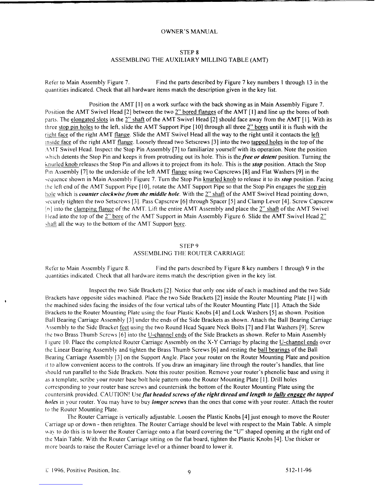
STEP3
ASSEN,IBLING
THEMAINTABLETOTHE
BASE
Refer
toMainAssemblyFigure2.
(Main
Table
Assembly52685021)
Find
theparts
describedby Figure2ke1numbersI through7 inthe
quantitiesindicated.Checkthatallhardwareitemsmatchthedescription
givenintheker lrst
Position
the Main
Table
[1]
ontheassembledBase
(step
2).
CAUTION: The
tgble
*eishs
aporoximatelv
90lbs
andthisstenmay requireassistance.
Be
sure
topositionthetable
* rththe
"U" shaped
end
andundersideT-slotoverthe
large
cutouthole
inthe
longsideof the
Base.
Looselysecure
theTable
totheBase
using
the
holesinthetopflangeof
theBase
and
Bolt
[3]
and
Washer
[J].
Whenallhardrrarersin
place.
besureIo
securelv
tightenallbolts.
AttachtwoPositionerLevelers
[2]
totheundersideofthe
Table
as
5ho\\ninFrcurcl. usrng
Screw
[7]
andWasher
[6].
Thread
the
Thumbscrews
[5]
intothethreaded
holes
oiPosrtrtne:
l.erelers
[2].
lnsertthesixLockingSetscrews
[0] into
theRouterSupptrn
I)rt,n-ln
p1311'
lal P.:;e
theRouter
Suppon
Drop-ln
Plate
in
the
rabbetcd
recessin
the
Main
'l'able
and
Ir'relttu:rir{
thclour.,.n:.':
I L
ir:rS Selscre$s.
Ad.lust
theside-to-side
fit
byad.justing
thetu'ol.ockingSr'tSCft'rrs
ltrt:itedrr::hertle:
Place
your
routerontheRouterSupporf
Drop-lnPlat.'an,l
ptr:ii.trr.
.i
lrr
i:itrrri!,:\ 3nienl
accesstothe
controls.
Note
this
routerposition.Rernove
)our
router5
phcn..lrc
b,ase
rr.: --:rSlt
J)
J:ern9:Jle.
scribevour
router
basebolt
holepattern
onto
theRouter
Support
Drop-lnPi,:icl)rrl,
hrlr- ;.:-3-ronc::i :. :..
-: :!ruter
basescrens
andcountersinkthetopoftheRouterl\,lountingPlatcusrnS:hccct.rnis:.r\::.r\:ie;
'--\';i()\'Useflatheaded
scrcwsof thefight threudundlengthlo fully engapethetuppedhttles
.:.
'.i-r rt]urir 'r: - :'.:' hare
to buylonger
screws
than
the
onesthatcome
with
)-our
router.
AnachthcfrrLlirii ::..R-
-:.: \tou:.:.:i ? j:3
S'l
l:P
l
ASSENIBLI\C tllf: Pr
ts;' r \i {
(Positioner
.-\::enrb.":l: 3
j
Ret-ertoMainAssemblyFigure
j. Firrdthe
panr
Jes.:.:;::, i :-:r I xcr1-"':.-':.
. ::.:ough
24inthe
quantities
indicated.Check
that
allhardrvareitenrsnratchthc;e:;::::..
- i .i: iirri3ri. .:
Placethe
PositionerSupport
u]on a
rrork
surt'ace
rllhe::: : ::: es-:::ce;t :::: ,.
::::ranple.)
Insert
thetwoBall
Bearings[0]intothetwocounterbored]E'holes::i..::.e::s.-:'.i.Po::,-3-:-::.:r[].TheBall
Bearingouterdiameterisdesigned
as
a
slip
fitintothesebrrrc:a..J,
l:i B:..Bea:lngs
s:..- : :3 \e:: jquare
to
the
bores
uhile
insertingto
prevent
binding.
Screu,theFixed
End
Acrne
Nut
[3]
intothe5 l6-l8lrr:i:r.l rl:: ,:,:
Cr:-:lase
?--:
i .-r3:{ssembly
[2]
as
shown
inFigure
3.IMPORTANT! Tishtenbr handonlr
Position
Carriage
Positioner
Assembl;
[2]
urth
the
r. .e::::.: :r:: .-:'
'i' a.:g:.e:
bothends
of PositionerSupport
[1. InsertGuideRod
[-] lh:..ugr.::,e:.:. ": ,::eeni l: '
bearingboreof[2]andthenthroughtheboreattheothcrcnir,i'i.'\..;-::3.:Jitii-l :l
surfacesof[]then secure
[7]
in
[]with two
setscre\\s
[81
as
sii\\;i :nF::-:e -:
With
theopeningof Il] facing
y'ou.
insenAcnrc'Lerd:cre*
'91
:ni..i:.e:!,reoi:r'.e:lshl
nanlBall
Bearing
[10].
The
l/4-20
threadedendof [9]
mustbeon
therrghrl'hen:r'.rerJ'q
l.rn\ra\ ::io i-. ,,rhrch
has
alreadybeenscrewedinto[2].Makesure[9]doesnotprojectrntothc.r3''\St)i-:'lirtdols.
Ih.n:.ici[9]
offuntil
thejawareaof
[3]
isclear.Alignthematingja*sofFrceEnd.{:;lerut
l; ',rr:n:retd*Sraii:i:n.trullr
engage
thc
jaws.
Holding
[4]in
this
position,
continuescrolins
[9]
rnto
[-r]
rnj i-l]
I'eepr:i
IJ]
as;..,:ell [-l]as
possible.
Whenthethreadsof[9]har,eengagedboth[3]and[1].both[-r]
andlll
'.rrll
r;:3)runir \er:.s,rpAcmeNut
Spring
[6]
andthenAcmeNut
Collar
[5]
overthe
por-tionof [9]
trhrch
ha:arreiJ\
rr>:ei li.:'rr.gh
[-rl
and
[4].
Thread
[5]
onto
[1]
slightll'
compressing
[61.
''\
.:: ::.3
;
.' boresat
::.::.::.:,-;gh
the
-:i. '\.ll ::e
outside
O 1996.
Positive
Positiorr 5ll-rl-96

OWNER'SMANUAL
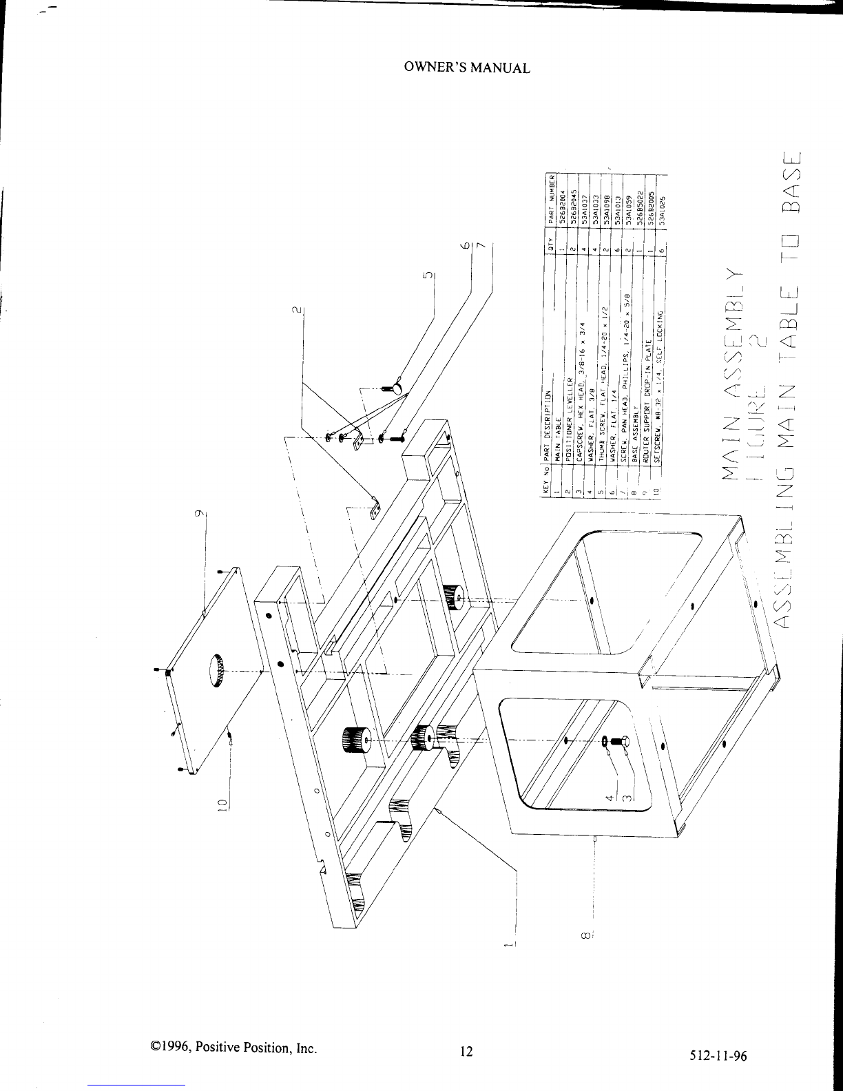
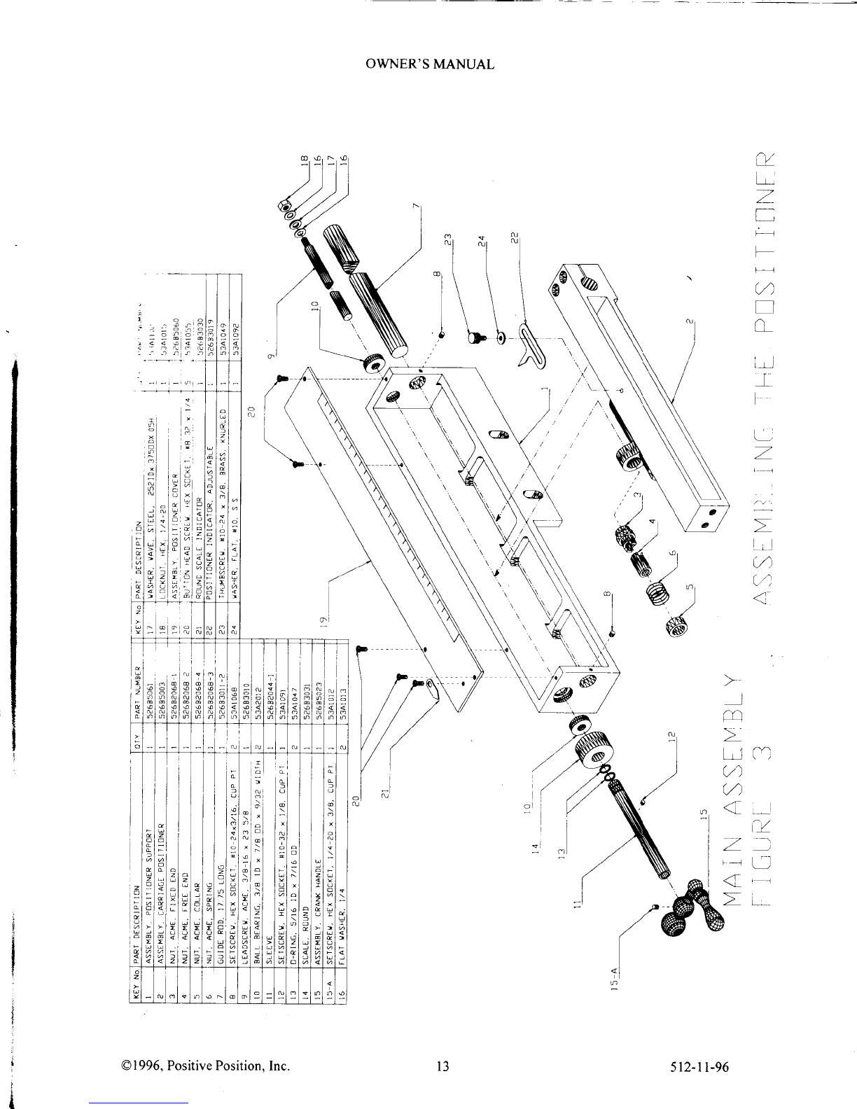
STEP
4
ASSEMBLINGTHE POSITIONER
(CONTINUED)
Continuetuming
[9] untilitpasses
through
the
ID ofthe
BallBearing
[0] on
the
left
and
projects
beyond
- . :frrut
5.5inches.
Apply'
afew
dropsof light
machineoil tothetwoO-Rings
fl 31andslide
them
overthe
endof Sleeve
Il I
]
"
- ;n isnearest
the
fwoO-ring
grooves.
Position
one
O-Ring
ineach
groove.
Next,slideRound
Scale
[4] over
the
' t-)-
Rings
[ 3
].The
scalemarkingsof [ 4] mustbe
at
theend
ofthe
assembly
andtheknurled
part
of fl 4l must
-',:..u
ardthecenter.If not,turn
il 4] aroundnow.
Slidethisassemblyover
the
left
endof [9].
Slide
the
bore
of CrankHandleAssembly
[15]
overtheendof [9]until
[9] bonomsoutinthebore.Secure
' to[9]withSetscrew
[15-A].
Tighten
securely.Push
the
CrankHandle
andLeadscrew
Assemblyallthe
wayto
-
i :rsht.Thet/u20
threaded
endshould
beoutsidethePositioner
SupportAssembly
Il]. Applytwo %FlatWashers
^ theWaveWasher
Il7] andthe
t/*20
Locknut
[ 8].TightentheLocknuttoremove
axial
play
ofthe
::iscrew.Donotovertightenasthiswill make
the
Leadscrewdifficult
toturn.
InsertSetscrew
fl2] into
Sleeve
andtighten.
Applyafewdropsof lightrnachineoil toGuideRod
[7]
just
outside
ofthetwo linear
bearinssatbothends
' ,-
.rrriagePositioner
Assembly
[2].Slide
the
CarriagePositionerAssemblv
[2]backandforth
repeatedly
towork
-: orlinto
the
linearbearings.WipetheGuideRod
[7]
clean.
Place
Cover
[9] onPositionerSupport
[]and securewithfour
screws
[20].
Attach
RoundScaleIndicator
- ' tocover
with
screw
[20].
Attach
AdjustablePositionerIndicatortoCarriagePositioner
[2]withThumbscrew
-:; andWasher
[2a]
in
thesequenceshown.
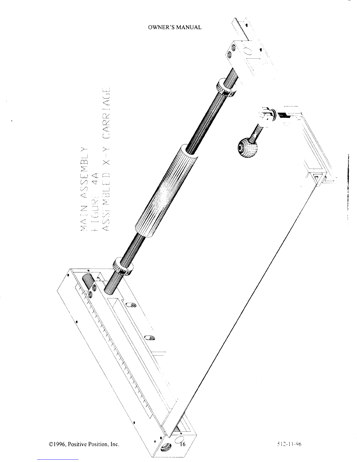
STEP
5
ASSEMBLING'THEX-YCARRIAGE
i.cter
toMainAssemblyFigure
4. Find
the
parts
described
by Figure
4 keynumbersI throughl5 inthe
:uantitiesindicated.Checkthatallhardware
itemsmatchthedescription
given
inthekeylist.
Placethe
bottomedgeofthePositionerAssembly
[5268500
I
] ontopof theLevelers.
[See
..*e lersinMainAssembly
Figure2.1
Secure
thePositionerAssemblytothe
Main
Table
[2]withtwoCapscrews
1,11.
Finger
tightenonlyatthistime.Attach
CarriageTrack
[6]tothe
MainTableusingtwoCapscrews
[4], three
\\ ashers
I l
] andthreeDisk
Springs
[ 2].
Notethat
theDiskSpringsareneartheedge
of the
MainTable
and
the
\\'ashers
areinboard.
Placetwoeach
Washers
and
Disk
Springsbelowthetableand
oneeachabove.
[This
stackup
na1changelaterwhen
levelingtheX-Y CaniageAssembly.]
SlidetheLinearBearingAssembly
[7] onto
theGuide
Rod
[3].[Note:
if youhave
purchased
theClamp
Kit 85028,
slidethe
twoShaft
Collars
[5]onto theGuideRodas
.rell
placing
on
ateach
endof theLinearBearingAssembly.]Slide
oneendoftheGuide
Rod
intothe%" boreof
:reCarriagePositioner
IKeyNo.2, MainAssemblyFigure3.]Slidethe'io"boreofthe
BallBearing
Caniage
\ssembly
[5] ontotheotherend
ofthe
GuideRod.ScrewtwoCapscrews
[8]eachinto
bothends.Snug
tighten
only
:: this
time
withtheAllenwrenchprovided.
Screw
the
SupportAngle
[4]ontotheendsof the
Caniage
Positioner
:ndBallBearingCaniageAssembly
usingfourCapscrews
[9].Use
the
twoWashers
[10]
ontheBallBearing
.arriase
Assembly
endonly.At thistime,
goback
andsecurelytighten
thetwoCapscrews
[ 3].Check
toseethat
:.:e
ballbearingsof theBallBearingCaniageAssemblyaresittingontopofthe
Caniage
Track.If necessaryadjust
:r.e
position
oftheBallBearing
CaniageAssembly.
Once
thisisdone,securelytightentheeight
Capscrews
[8]&
.l TurnthePositioner
CrankHandletocheckthattheX-Y Carriage
Assembly
movesfreely.
Wewill level
the
X-
': CarriageAssemblylater.
Apply
a
fewdropsof lightmachineoil toGuideRod
[3]
just
outsideofthe
two linear
bearinssatbothends
: ::e LrnearBearingAssembly
[7].
Slide
the
LinearBearingAssembly
[7] backandforthrepeatedlytoworkthe
:nto
thelinear
bearinss.Wipethe
Guide
Rod
[3] clean.
rqq6 PosirivePosition,Inc 512-tt-96

OWNER'S
MANUAL
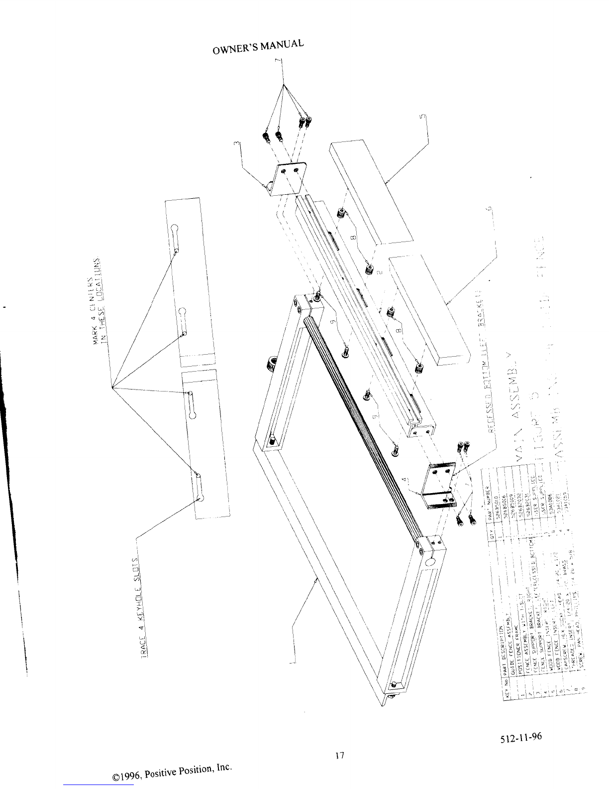
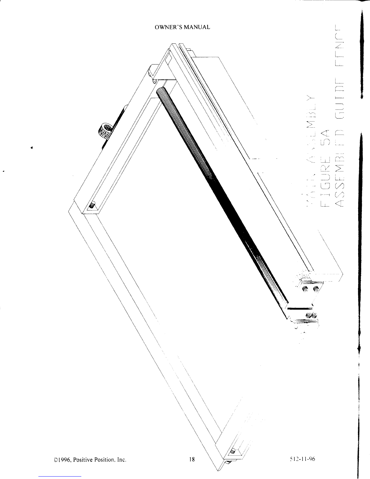
STEP6
ASSEMBLINGTHEGUIDE
FENCE
[526B5o
lo]
Referto Main AssemblyFigure5. Findthe
parts
describedby Figure5 key numbersI through9 inthe
quantities
indicated.Check
thatall hardware
itemsmatchthedescription
givenin thekey list.
AttachtheRightFence
Support
Bracket
[3] andtheLeft Fence
Support
Bracket
[4] totheFence
Assembly
[2] with four Capscrews
[7].Notethat
theLeft FenceSupport
Bracket
[4] hasarecessonthebottomto
provide
clearance
fortheoptional
DustCollectorattachment
85045.
Attach
the
resultingassemblytotheX-Y
Caniage
Assemblyof MainAssembly
Figure4 usingfourCapscrews
[7].
Make
twoWoodenFenceInserthalves
t4]
& t5] fromscraphardwood.
WoodFenceInserts
shouldbe%"thick
and90"beveledononeend.Measure
the
distance
fromtheundersideof theAluminumFence
T-Slottothe
MainTablesurface.Makethe
width
oftheWood
FenceInsertsequal
tothisdistanceless
l/8". Makethe
rightWoodFenceInsert
12.5"longandtheleftWood
Fence
InsertIl" long.Positionthe
WoodFenceInsert
halveswiththebevel
inthecenterasshownandlineup
the
bevelededge
withthecenterofthe
RouterDrop-lnSupport
Plate
[Main
AssemblyFigure2 Key
No.9]. Holdingthe
WoodFence
InsertagainsttheAluminum
Fence
[2]andup
aqainsttheAluminum
FenceT-Slot,tracetheoutlineof
thefour
(4)Keyholesinthe
AluminumFenceonto
thebacksof the
WoodFencelnserts.Mark
the
centerofthe
narrow
endofeach
Keyholeasshown.Drill aflatbottomA318"
x 5i8"deephole
inthecenterofeachof thefour
locations
marked.Threadthe
fourBrassThreaded
Insertsintothese
holes.InsertthefourPanHeadPhillipsScrews
[9] intotheBrassThreaded
Inserts.
Slide
theheadsof thePanHead
Philips
Screws
intotheke1'holeslotsand
tighten
theWoodFence
Insertsagainstthe
AluminumFenceinthe
desired
position.
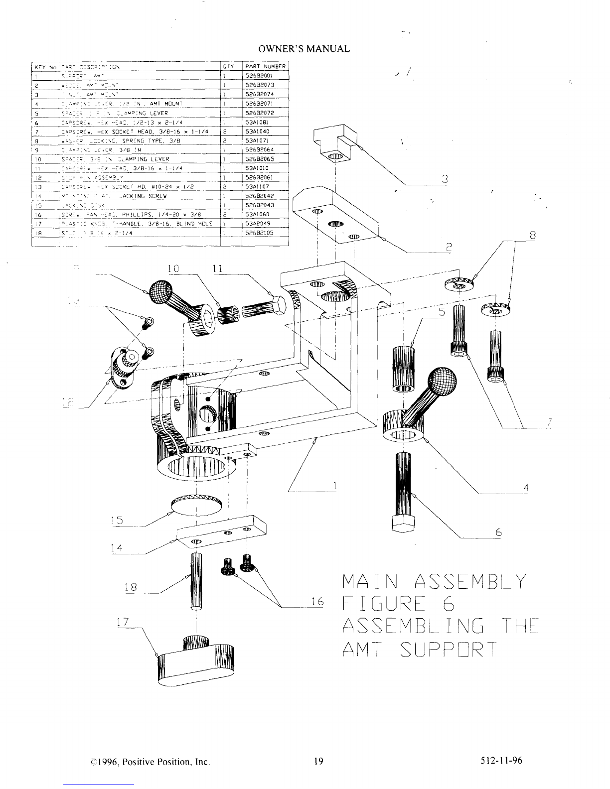
STEP
7
ASSEMBLINGTHE
AUXILIARY MILLING TABLE
(AMT)SUPPORT
Ref'ertoMainAssemblyFigure6. Findthe
parts
described
by Figure6 keynumbers
I throughl8 inthe
quantities
indicated.Checkthatallhardware
itemsmatchthedescription
given
inthekeylist.
Bolt
theAMT MountingWedge
[2]tothe
AMT Support
[ ] usingtwoCapscreu
s[7]and
LockingWashers
[8].
AttachtheStopPinAssembly
[12]
totheAMT SupportusingtwoCapscreus[13].
Pass
Capscrew
I l]through Spacer
[0] and
throughClampingLever
[9]making
surethehex
pan
ofthe
Clamping
Leverholeisfacingthe
headof Capscrew
[11].
ThreadCapscrew
[11]
intotheAMT Supportclamping
flangeas
shown.
AttachtheJackingScrew
MountingPlate
[4]to the
AMT Support
undersideusingnvoPanHeadPhillips
Screws
[ 6].Insert
Stud
[ 8] intothePlasticT-Handle
Knob
[ 7]andtightenusingdouble
3
'8-
16nuts Threadthe
assembled
T-Handle/StudintotheJackingScrew
MountingPlate.
Drop
the
JackingDisk
[ 5] intothe
top
ofthe2"
boreoftheAMT Support.
PassCapscrew
[6]through
Spacer
[5]andthroughClamping
Lever
[4] PassCapscreu'
[6]through
thel" bore
oftheAMT Supporttop
flange.throughthe
AMT MountingWedgeand
loosely
screu
Capscrew
[6] intothe
AMT MountT-Nut
[3].Lift theentireassembly
andmaneuverthe
AMT llount T-Nut
[3]
into
either
end
oftheAMT MountingT-Slotlocated
undertheMainTable.
[See
MainAssembllFigure2 for
location
oftheAMT Mounting
T-Slotl.SlidetheAMT Support
Assemblytoa
position
atabout
themiddleofthe
AMT MountingT-Slotandlocksecurelyinto
place
using
theClampingLever
[5].
O 1996,
PositivePosition.Inc 512-n-96
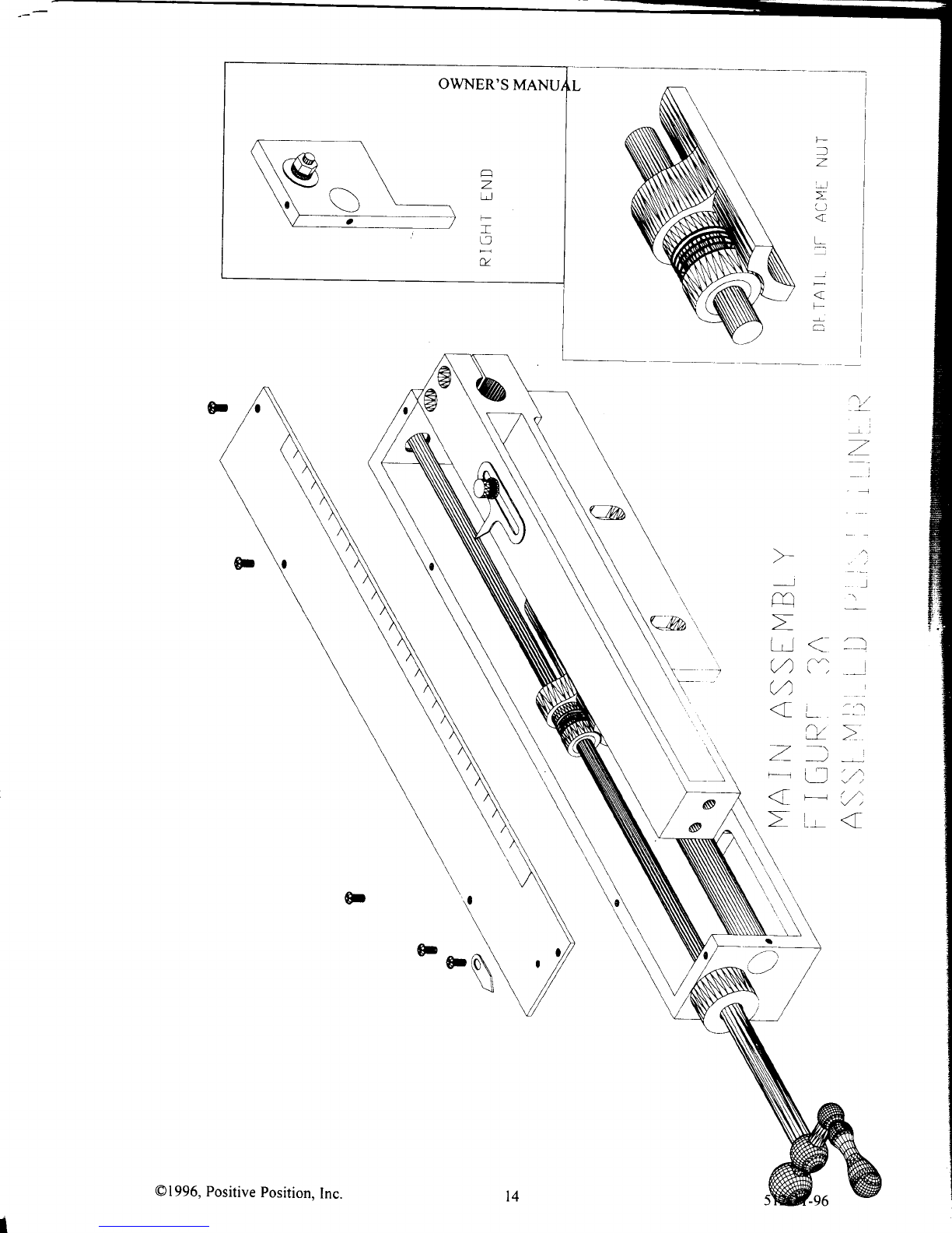
OWNER'SMANUAL
STEP8
ASSEMBLING
THE AUXILIARY MILLING TABLE (AMT)
Ret-er
toMainAssembly
Figure
7. Find
theparts
describedby Figure7 keynumbersI throughl3 inthe
quantities
indicated.
Check
thatallhardwareitemsmatchthedescription
given
inthe
keylist.
PositiontheAMT [ ] on
aworksurface
with
thebackshowingas
inMainAssemblyFigure7.
Position
the
AMT SwivelHead
[2]betweenthetwo2" bored
flanees
ofthe
AMT []and lineuptheboresofboth
parts.
Theelons,atedslots
inthe
2" shaftof theAMT Swivel
Head
[2]shouldfaceaway
from
theAMT Il]. With its
rhree
stop
pin
holes
totheleft,slide
the
AMT Support
Pipe
[0]through allthree2" boresuntil
it isflush
withthe
rieht
faceof the
rightAMT flanee.Slidethe
AMT SwivelHeadalltheway
totherightuntilit contacts
the
left
rnsidefaceofthe
rightAMT flanse.LooselythreadfwoSetscrews
[3] intothefwotappedholesinthetop
ofthe
\\1T SwivelHead.
Inspectthe
Stop
PinAssembly
[7]tofamiliarize
yourself
with itsoperation.
Notethe
position
irhich
detentstheStop
Pin
and
keepsit from
protruding
out
itshole.Thisis
thefreeor detent
position.
Turningthe
inurled
knobreleasestheStop
Pin
andallowsittoproject
fromitshole.Thisisthe
slop
position.
Attachthe
Stop
PrnAssembly
[7]to theundersideof the
left
AMT flanseusing
fwoCapscrews
[8] and
Flat
Washers
[9] inthe
.cquence
shownin MainAssemblvFigure7.Turnthe
Stop
Pin
knurled
knob
toreleaseitto its.r/op
position.
Facing
lheleftendof theAMT Support
Pipe
[ 0],rotate
the
AMT SupportPipesothatthe
Stop
Pinengagesthe
stop
pin
holewhichiscounter
clockwisefrom themiddlehole.tNilhthe2" shaftof theAMT SwivelHead
pointing
down,
)ecurelytightenthe
two Setscrews
[31.
PassCapscrew
[6]throughSpacer
[5]andClampLever
[4].ScrewClapscrew
l6l intotheclampineflangeoftheAMT. Lifi the
entireAMT Assemblyandplace
the
2" shaftofthe
AMT Swivel
tteadintothetopof the
2" boreof the
AMT SupportinMainAssembly
Figure
6.SlidetheAMT SwivelHead2"
r,haft
allthewa1'tothebottomof theAM-f Supportbore.
s fllP 9
ASSEMBLINGT'HEROUTERCARRIAGE
Refer
toMainAssemblyFigure8. Find
the
parts
describedbyFigure
8keynumbersI through9 inthe
.'1uantities
indicated.
Check
thatallhardwareitems
rnatch
thedescription
giveninthekeylist.
Inspect
the
twoSideBrackets
[2].
Noticethat
onlyonesideof each
is
machined
andthetwo Side
Bracketshaveoppositesides
rnachined.
PlacethetwoSide
Brackets
[2] inside
theRouterMountingPlate
[ ] with
rhe
machined
sides
facingtheinsidesof thefbur
verticaltabsofthe
RouterMountingPlate
[]. Attachthe
Side
BracketstotheRouterMountingPlateusingthefourPlasticKnobs
[4]and
LockWashers
[5J
as
shown.
Position
BallBearing
Carriage
Assembly
[3]under
theendsofthe
Side
Brackets
as
shown.
AttachtheBallBearingCarriage
\ssembly
totheSidcBracket
feet
usingthe
twoRoundHeadSquareNeckBolts
[7] andFlat
Washers
[9].Screw
thetwoBrass
Thumb
Scrervs
[6] into
theU-channelendsoftheSideBracketsasshown.
RefertoMainAssembly
lrrgure
10.
Placethe
completed
Router
CaniageAssembly
ontheX-Y Carriage
byplacing
theU-channelendsover
rheLinearBearingAssemblyandtightentheBrassThumbScrews
[6] and
restingthe
ballbearinssofthe
Ball
BearingCarriageAssembly
[3]ontheSupportAngle.Place
your
routeronthe
Router
MountingPlateandposition
rttoallowconvenientaccesstothe
controls.
[f you
draw
an
imaginarylinethroughthe
router's
handles,that
line
shouldrun
parallel
tothe
Side
Brackets.Notethis
router
position.
Remove
your
router'sphenolic
baseand
using
it
.lsatemplate,
scribe
),our
router
base
bolt
hole
pattern
onto
the
Router
MountingPlate
[]. Drill holes
conesponding
toyour
routerbase
screwsandcountersink
the
bottomoftheRouter
Mounting
Plate
using
the
countersink
provided.
CAUTIONI Use
flat heudedscrewsof theright threadandlengthtofullv ensssethetapped
holestnyourrouter.You mayhave
tobuylongerscrcwsthanthe
ones
that
comewith your router.Attachthe
router
tothe
RouterMountingPlate.
The
RouterCarriage
isvertically
adjustable.Loosenthe
PlasticKnobs
[4]
just
enoughtomovetheRouter
Carriage
up
ordown
- then
retighten.
The
RouterCarriage
shouldbelevelwithrespect
totheMainTable.A simple
\\a\ todothisisto lower
theRouter
Carriageontoaflat
boardcovering
the
"U" shapedopeningatthe
rightendof
theMain
Table.
With
the
Router
Caniagesittingon
theflatboard,tightenthePlasticKrobs [4].Use
thickeror
moreboardstoraise
theRouterCarriaselevelora
thinnerboardto lowerit.
e' 1996,PositivePosition,Inc 512-11-96

OWNER'SMANUAL
STEPIO
ASSEMBLING
THECARRIAGELOCK
Refer
toMainAssemblyFigure9. Findthe
parts
describedby Figure9 keynumbersI through6 inthe
quantitiesindicated.
Checkthatallhardwareitemsmatchthedescription
given
intheke1list.
PasstheStudandHandleLockAssembly
[2]throughtheBronzeFlat
S'asher
[.1]
andnro Disk
Springs
[5].
IMPORTANT! TheDiskSpringsaredished
which
is
whatgives
themtheir
springBesuretheDisk
Springsareanangedsuchthattheyaretouchingbacktobackattheircenterholes.Next.
pass
the
studthroughthe
3/8"boreatthe
rear
oftheBallBearingCaniageAssembly
[ ]. PlacetheLockClampAngle
[3] overthesrud
and
thread
theLocknut
on
the
endof thestud.TheLockClampAnglemustengagethetopflangeoi the
CarriageTrack
[Main AssemblyFigure4, Key No. 6]. TheCarriageLock Assemblyisunlockedwhen
the*nob is verticaland
lockedwhentheknob ishorizontol.AdjusttheLocknut[6] to giveadequateDrskSprineforceto lockthecarriage.
IMPORTANT! Donot
overtightentheLocknutas
excessive
lockingforce
rr
rllcausethe
b,allL'earingsto tarl
prematurely.
WiththeCaniageLockAssemblyinthe
unlocked
position.
the\-\ Carriase
.:.r:ld mor.etieelr
whenthePositioner
CrankHandleisturned.CAUTION! Donotturn
lhePc)srliofrcr
Cra:r'ii.:.:.iie
uith theCaniase
LockAssemblyinthelock
position
asthismaydamagethe
Positroner.{ssemb,r
l0
e 1996.Positive
Position.Inc.

OWNER'S
MANUAL
t/
MA
i \,1
ASSTIVBLY
t IGt,]RT I
ASSIiVEL
I i\G -tFrl
EASI & L[G SI-t
PART
DESCRIPTI
BASE ASSEMBLY
(STANDARD)
CAPSCREU.Htx HEAD. 1/4-20 \ 3/1
VASHER,
FLAT I/{
INTERNALTOOTH,
TYPE
B, I/4
NUT, HEX JAH, I/4-20
T ASSEHBLY
(OPTIONAL
ACfSSORY)
'ODI, I 5 DIAH RUBBIR,
l/?-13 x ? STUD
NUT, HEX, I,/2_I3
SIIFFENER, LON6
STIFFTNER,
SHDRI
BoLT. RoUNDAEAD, I/4-2o x 5/8
NUT, HfX, I,/4.20
VASHER,
LOCK, INTfRNAL TOOTH,
TYPt B, I/4
CAPSCREv,
HEX HEAD. 3/8-16 x 3/a
IASHER,
FLAI,3/A
R, LUCK, INTERNALTOOTH,
T"ti.iA
NUT, HfX JAX, 3/8 l6
53al033
c-
4{!
l't / \ t4
O
I996.Positive
Position. 512-l
l-96
OWNER'S
MANUAL
L-l,-l
(/)
{
an
T
l--
;*, J
rrtu {
(/) I
7)
<- r z
:',/
.a-,{
* a,-
Z
t2
ll
ll
l"i
tl
-l
\1
2
:l
;
tl
-1
v,l
a)
I
I
i
l
r-i
lel
zi
iIl
]F
l:i
+
hl
si
ll
u
\
512-l
l-96
@1996,
Positive
Position,
Inc.
iri ru.Tpaci-
orsc*,
"i*J
ASSEMBLY,
POSITIONTR
SUPPORT
ASSTMELY,
CARRIA[t POSII
IONTR
KEvr.fpaBr orscprprtol
T7 VASBIR,YAVE,
STIfL asa:0":isrnx
os"
9
r^l
o\
(D
I
NU] ACMI, FIXfD tND
NUT, ACMI, FREE IND
1
s.,o'o',,
1
i 5;1685060
53A1055
52682068 l
5268e068 2
5a6B30rl
-e
53Al068
2l I
oO:\t SCA.t I\0 1
CA 0a 52683030
a0
'o
'# ?3
-'-''
Y?4
*____-,-
(?
t-^
{
z
lTl
ctt
3
z
(-
-
l5
N)
I
\o
o\ \4A
i N ASSf IVELY
i lrJrrRi 3
NUT, ACMI, COLLAR
NUI, ACME,
SPRIN6
GUIDE
ROD,
]7 75 LON6
SETSCRty,HEX
SOCKtT.
Bl0-3a x 1/8. CUP
Pl
0-RING. 5/16 lD x 7/16 0D-
SCALE, ROUND
ASSIMBLY, CRANKHANDLE
POS]TlONER
INDICA
iHUfBSCRE!,
*10 24 x 3/8, BRASS.KNTRLED
,ASHIR, FLAT, {1
O, S S
SETSCREH,HtX SoCKET,
i/4 2D x 3/8. CUP
Pl
@.,
\44 ^SSi \/
il fl\[ -!L PISI f ll_1
i\tR
F
l
z
rl
:
-
al _l
t.. :.-
(-z \-
!--L z'
l*r
Ll './:
7,
L{
i
aY)
LLI
(/)
(a
.'
T
-
''t '21
[ \,\
t4
,€
\o
OWNER'S
MANU
a
3
I
t-.)
u
@1996,
Positive
Position,
Inc.

OWNER'S
MANUAL
lli
lllli
)
t't'
II
T
\1 -/7
/n
(,/\
-''i.".
r- j /^j
^l
{
O1996,Positive
Position,
Inc. l5 512-tt-96
\
,-\
6*"':-'
\"
OWNER'SMANUAL
ir,-l
r-
!J
4
\
-
a
\*-,
-l
m\/
;r-r { Q
(l s]-1.
t"a --l
.r't t\l
^,/ \
.l I
z )'-,
,", ,I- l.,l
<T ' . l-z^,
}.-(-
\'
qr/
O1996,
PositivePosition,Inc
r.RACt
4 -K!JH0LL
SL0ls -- -\
vaR<
^ ' u-]
l,),,,nt
, \ --[Sr u - '*
(D
9,
-+
t, v,--
1
z
rrj
a
3
,JZ c
r
!--- .-\\ \
-P=--*
'.',7
'-"#,
-J
--:
-
.-----
.._
rr\..'lN1B
.- a
.
s
t-)
I'\
i .-r.
r';
&/. -,i
,\@;
/'
I
OWNER'SMANUAL
=
4-
\
,: ,' :--
.\,\
tl--
-.
/
tl -2
*_\
) -1
I 'l (,/\
i- i (./^
,4
L1 \
l
l
i
5ll-ll-96
O1996.
Positive
Position.Inc.
:as:i.,-
:c\ PART NUMBER
la- av- I52682001
Is26820
7
3
23!!3!11
5a6Ba0
7
I
\ :-iv3tN6 ifVER I5268e07e
/?-r3 ? t/ I53Al 081
:atr. -lx SOC([T HEAD. 3/8-16 x | 1/4 253Al
040
\., SFEIN6 IYPf, 3/A 53Al
071
52682064
\ :!AYP I
N6 LfVtR I52684065
t -rai. 3/B-16 x i \/4 53A1010
5?68?05t
(ET HD fl 0-24 |
/2 53Al I07
\: J 4' : -ACKI
N6 SCRfY I526
8204a
\: : s< 5?582043
Pf1!LLIPS l/1 20 \ 3/A 53A1
060
\:: iANDLf, 3,/8.16, Bi IND HBLT 53A2049
52582105
OWNER'S
MANUAL
jxfv t"o
.at-
r.-- - --.-
t'r-"--
T^ :-
T;--- . _
tr
4 '-t'"'
l-;-... .
'6 :4:5:
|.;-'.
-_:
l-e- ..,-
i, -:.ra
l0 S-r,r?
l12
tl a:"-a
l.'-.-
14 v_,\-
irs '_-i:.:i
1
6 S:.a.
Ill ;*
rt-
ro (-
t-
11
\
I6 IVAII\ ASStNlBt
Y
I IGUR[ 5
ASST[4EL
ING T!]
t
AI'4_t
SUPF!R_t
0
1996.PositivePosition.
Inc. l9 5t2-tt-96

OWNER'SMANUAL
4'.
,^'.- (
\\-
---
.) .)
CI1996.Positive
Position.
Inc 20 512-l
l-96


