Millipore NovAseptic GMP ATEX User manual

NovAseptic®GMPATEX
Mixer
Installation and User Guide

Notice
The information in this document is subject to change without notice and should not be construed as a com-
mitment by Millipore Corporation. Millipore Corporation assumes no responsibility for any errors that may
appear in this document. This manual is believed to be complete and accurate at the time of publication. In
no event shall Millipore Corporation be liable for incidental or consequential damages in connection with or
arising from the use of this manual.

NovAseptic GMP ATEX Mixer Installation and User Guide Foreword
Foreword
The ATEX mixer is designed for operation in the classification as noted by the product label. To ensure that
the mixer may operate in an ATEX defined environment the mixer must be in good working order before
operating.
Before using the mixer the user is responsible to ensure the following:
•The tank plate is installed properly to the tank and is checked with appropriate tools for concentricity
and alignment. This prevents any contact between Mixing Head, Outer rotor and tank plate. If the
tank plate is warped during welding or is not aligned properly with the tank surface the tank plate
must be removed, discarded and replaced with a new tank plate. It cannot be repaired if damaged.
•Check to ensure the mixer drive unit is in proper working order prior to attaching to the tank plate. If
the drive unit has been dropped check for any damage. Afterwards check to determine if it mounts to
the tank plate properly. If there is any damage to the drive unit ensure it is repaired before using.
If, when dropped, the outer magnet was damaged or the outer magnet drive shaft is bent, attach the
drive unit to the tank plate and manually check to determine if there is any contact between the outer
magnet and tank plate. If there is any contact do not operate the mixer and have it repaired prior to
use.

Contents Operator and Equipment Safety................................................... 11
Labeling..................................................................................12
NovAseptic GMPATEX Mixer Components.................................13
Required Tools........................................................................14
Optional Equipment................................................................14
Installation and Operating Parameters.........................................15
Noise level and Vibrations......................................................15
Installation....................................................................................16
Male Bearing Installation ........................................................16
Mixing Head Installation..........................................................18
Drive Unit Installation..............................................................19
Electrical Installation...............................................................22
Operation .....................................................................................26
Starting the Mixer....................................................................26
Operating Notes:.....................................................................26
Disassembly ...........................................................................27
Storage...................................................................................27
Recycle and Disposal.............................................................27
Cleaning and Sterilizing Procedures............................................28
Cleaning in Place (CIP) ..........................................................28
Sterilizing in Place (SIP).........................................................29
Installation ATEX Checklist ..........................................................30
Install the Male Bearing..........................................................30
Install the Mixing Head ...........................................................30
Before Installing the Drive Unit...............................................30
Install the Drive Unit ...............................................................30
Before Installing the Electrical Components...........................31
Install the AC Motor ................................................................31
Install the VFD System...........................................................32
Commissioning.............................................................................33
Valid Regulations....................................................................33
Installation Qualification Checklist................................................34
Installation Qualification ........................................................34
Maintenance Checklist.................................................................36
Spare Parts..................................................................................38
Troubleshooting ...........................................................................39
Standard Warranty.......................................................................42
NovAseptic GMPATEX Mixer Installation and User Guide 3

NovAseptic GMP ATEX Mixer Installation and User Guide 4
NovAseptic GMP ATEX Mixer Installation and User Guide 5
NovAseptic GMP ATEX Mixer Installation and User Guide 6

NovAseptic GMP ATEX Mixer Installation and User Guide 7

NovAseptic GMP ATEX Mixer Installation and User Guide 8
NovAseptic GMP ATEX Mixer Installation and User Guide 9
NovAseptic GMP ATEX Mixer Installation and User Guide 10
Operator and Equipment Safety
All installers and operators of the equipment must read and understand this•
installation and user manual before using this equipment. Failure to follow
operating and installation instructions could result in operator injury or damage
to the equipment.
Any attempt to use the NovAseptic GMP ATEX Mixer equipment in a manner•
not specified by Millipore Corporation may result in damage to the equipment,
voiding of product warranty, and possible operator injury.
Any of the following can damage the mixer:• external load, reaction forces,
torque, corrosion, erosion, fatigue and the decomposition of unstable liquids.
Prior to operation, the equipment must be fully assembled according to the•
instructions in this manual.
Use appropriate personal protective equipment and eye protection when•
operating the equipment.
Protect drive unit against dust.•
The drive unit may be heavy. Use appropriate equipment to avoid injury.•
Do not install components close to rotating parts of the GMP ATEX Mixer.•
During mixing operations, mixer parts may become hot to the touch.•
Do not insert fingers into equipment; pinching may occur.•
Check the magnetic parts of the GMP ATEX Mixer regularly for foreign•
materials.
Do not run with an empty vessel.•
Check that all components in the mixer are of correct size.•
Handle the mixing head and male bearing with care; bearing material is hard•
and brittle.
Keep electrically controlled medical devices and magnetically stored media away•
from magnetic parts of the GMP ATEX mixer.
The mixing head must always be completely submerged.•
Follow Ex regulations applicable to the GMP ATEX mixer.•
System must be properly grounded.•
!
NovAseptic GMPATEX Mixer Installation and User Guide 11
NovAseptic GMP ATEX Mixer Installation and User Guide 12
NovAseptic GMPATEX Mixer Components
Catalogue numbers and specifications for the components listed here can be found
on the appropriate specification sheet.
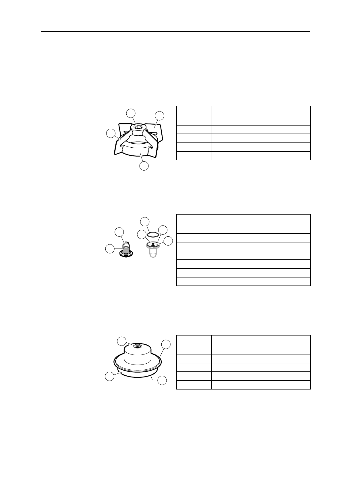
Mixing Head (AX#/12#)
Handle the mixing head with care. The bearing material is hard and brittle. Keep the
magnetic body away from any particles that may adhere to it.
Key
Number Description
1 Magnetic body
2 Wings
3 Silicone carbide female bearing
4 Serial number
Male Bearing (AX#/24)
The male bearing keeps the mixing head in a correct position; it mounts on the tank
plate inside vessel.
Key
Number Description
5 Stainless steel support
6 Silicone carbide bearing
7 Connection thread
8 Groove
9 O-ring
10 Serial number
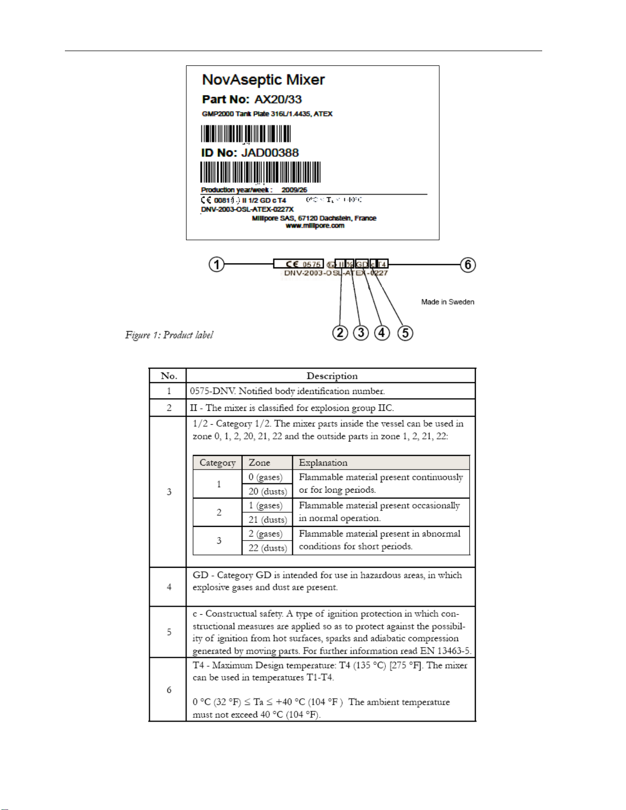
Tank Plate (AX#/33)
Each tank plate is marked with the serial number and a mill stamp that corresponds
to its heat number. The tank plate is welded onto the vessel and is considered an
integrated part of the vessel. The tank plate must comply with your local pressure
vessel code.
Key
Number Description
11 Male bearing connection thread
12 Welding edge
13 Drive unit connection flange
14 Serial number
xxxxxxx
3
4
2
1
x
x
x
x
x
x
x
5
9
6
8
10
7
11 12
14
13
p
late
NovAseptic GMPATEX Mixer Installation and User Guide 13
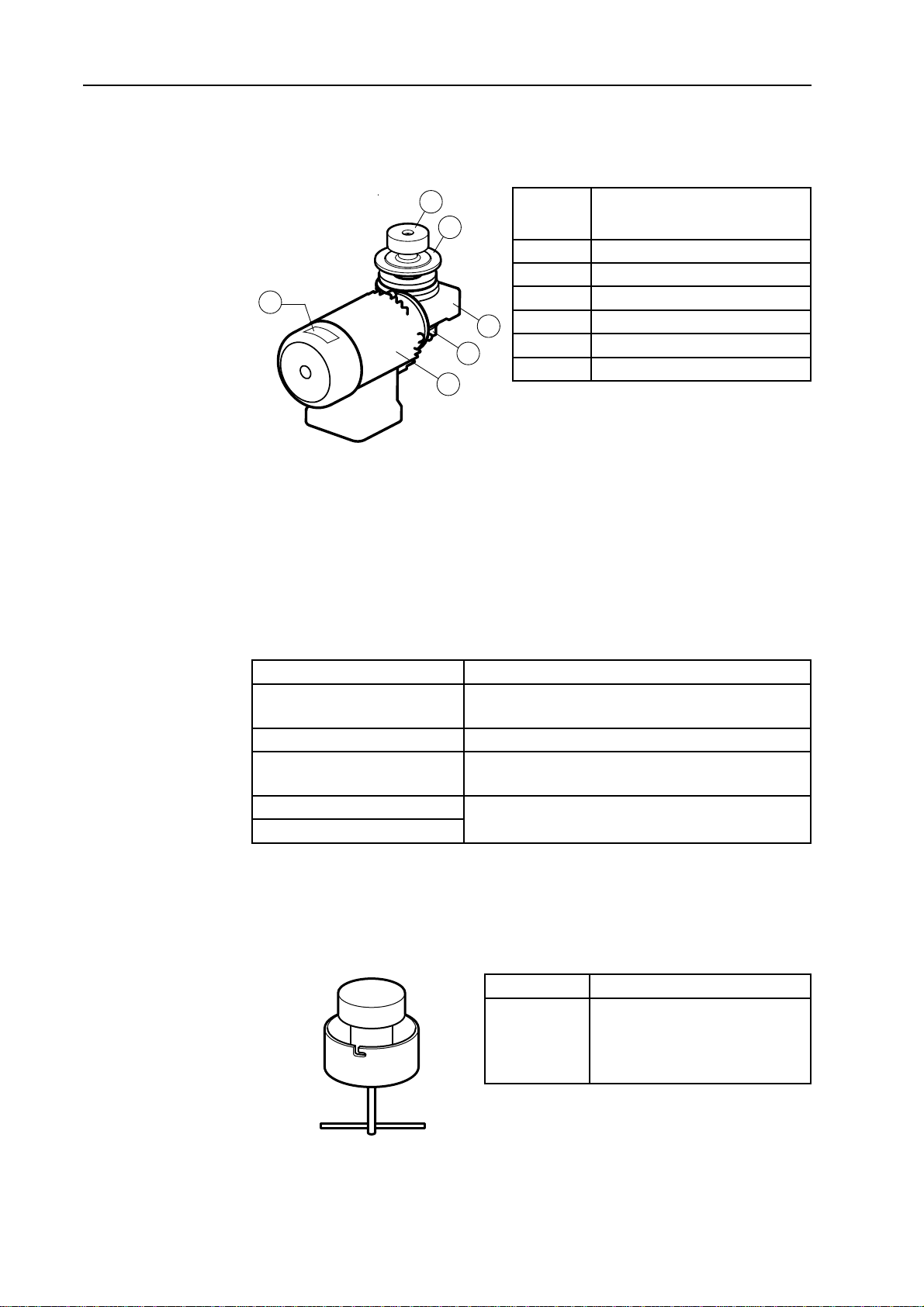
Drive Unit (AX#/41-E#)
The drive unit delivers the rotating torque to the mixing head and is mounted on the
outside of the vessel.
Key
Number Description
16 Magnetic outer drive head
17 Tank plate connection flange
18 Gearbox unit
19 Revolution counter
20 Motor
21 Serial number label
Required Tools
The following tools are required for installation of the NovAseptic GMP ATEX
Mixer.
The NovAseptic gauges 1 and 2 are included with the tank plate; the other tools
(shown below) are not included with the mixer and are available from Millipore.
Component catalogue numbers and specifications can be found at www.millipore.
com.
Description Purpose
Multi tool (GT#/25) Installation tool for mixing head and male bearing
for use in small vessels.
Tightening tool (GT#/26) Installation tool for male bearing.
Heatsink tank plate (G94-#) Attached to the tank plate during welding to pre-
vent deformation.
NovAseptic gauge 1 (G91-#) For verification of geometry after welding.
NovAseptic gauge 2 (G92-#)
Optional Equipment
The following is available from Millipore. Catalogue numbers and specifications for
the component shown here can be found at www.millipore.com.
Description Purpose
Mixing head
attractor
(GT#/AW)
Keeps the mixing head in
place when vessel is moved.
Replaces the drive unit during
transport.
21
16
17
18
19
20
x
x
x
x
x
x
14 www.millipore.com
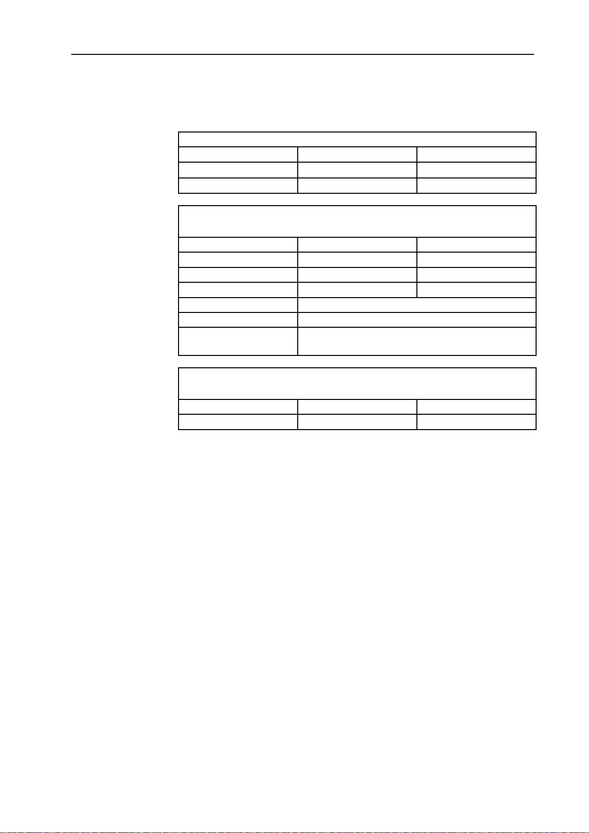
Installation and Operating Parameters
Please refer to the appropriate product specification sheet for more information.
Tank Plate
Parameter Minimum Maximum
Temperature -80 °C (-112 °F) 200 °C (392 °F)
Pressure -1 barg (-14.5 psig) 10 barg (145 psig)
Mixing Head, Male Bearing, and Tank Plate
Define the operating parameters inside the vessel.
Parameter Minimum Maximum
Temperature 5 °C (41 °F) 135 °C (275 °F)
pH 1 14
Viscosity 1 cP 800 cP
Media Media may not contain magnetic particles.
Rotation speed See Product Specification Sheet.
Minimum acceleration
and deacceleration time
Five seconds (specific to each application; set accord-
ingly).
Drive Unit
Defines the operating parameters outside the vessel.
Parameter Minimum Maximum
Ambient temperature 0 °C (32 °F) 40 °C (104 °F)
Noise level and Vibrations
Noise levels are measured according to ISO®1680 standard, and are within
maximum levels specified by standards CEI 2–24/IEC 34–9. Vibration falls under
standard class N, as specified by standard CEI 2-23/ IEC 34-14.
NovAseptic GMPATEX Mixer Installation and User Guide 15

Installation
Use the Installation Checklist and the Installation
Qualification Checklist (in this manual) as guides
for installing the mixer and initiating use. Use the
Maintenance Checklist as a guide for follow up
care of the mixer. For welding of the Tank Plate
useGMP ATEX Welding Instructions.
Install the GMP ATEX Mixer components in the
following order:
1. Tank plate
2. Male bearing
3. Mixing head
4. Drive unit
5. Revolution counter
Male Bearing Installation
See NovAseptic Mixer Male Bearing Installation Guide 00101868PU for additional
information.
The vessel must be clean and completely dry inside.•
Do not use grip tools on bearing surfaces.•
Follow all local safety codes before entering the vessel.•
Handle the male bearing with care.•
Mounting the Male Bearing
Ensure proper position of the O-ring on the male bearing.1.
For minimal friction, lubricate the visible part of the O-ring with a small amount2.
of purified water.
!
4
x
x
x
x
x
x
5
2
1
3
H2O
360°
16 www.millipore.com
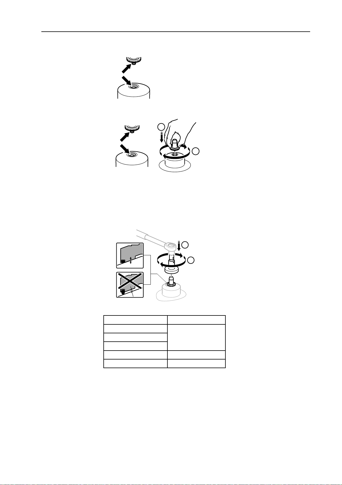
Remove the protective cap. Ensure that the thread connection in the tank plate3.
and male bearing are clean, dry, and free from foreign material.
Tighten the male bearing clockwise by hand into the thread of the tank plate,4.
making sure that it is aligned with the center line of the tank plate.
1
2
Position the male bearing in the appropriate tightening tool or multi-tool with a5.
torque wrench. Ensure that the tool fits the nut. Tighten the bearing to metal-to-
metal contact by applying recommended torque according to table below.
Important: Ensure metal-to-metal contact by applying recommended torque in
table below. If bearing is not installed properly it may come off.
3
4
Catalogue Number Torque
AX05/24
6 Nm (4.4 Lbft)AX1/24
AX510/24
AX20/24 13 Nm (9.6 Lbft)
AX50200/24 30 Nm (22.1 Lbft)
NovAseptic GMPATEX Mixer Installation and User Guide 17
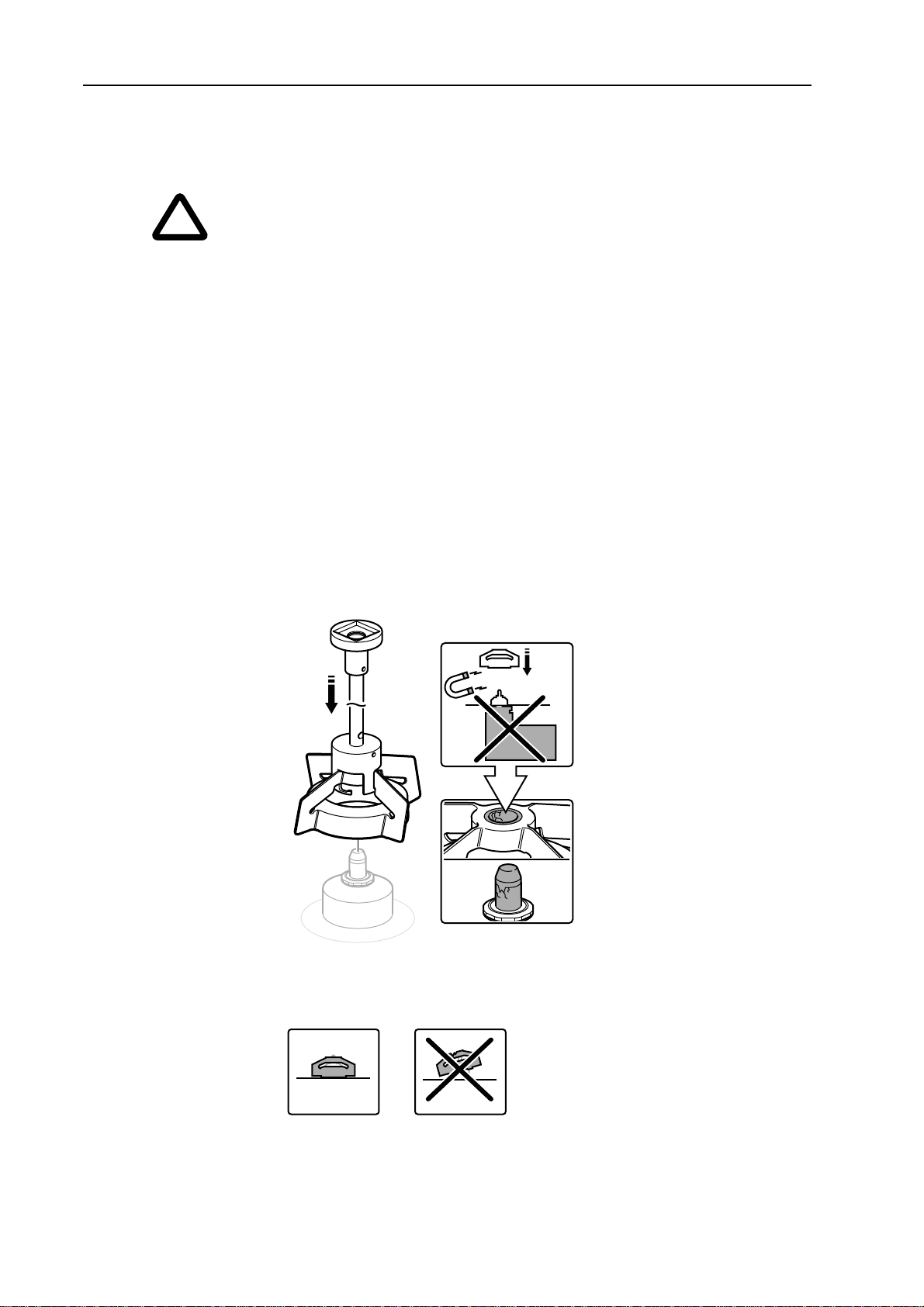
Mixing Head Installation
See NovAseptic GMP Mixing Head Installation Guide 00101787PU for additional
information.
Handle the mixing head with care.•
Use extreme care when mounting the mixing head on to the male bearing;•
mixer bearings are brittle.
Do not mount the drive unit before installing the mixing head. The powerful•
magnetic force between the mixing head and the outer drive head may cause
severe damage to bearings as well as personal injury.
Follow all local safety codes before entering the vessel.•
Remove any foreign magnetic particles from the mixing head.1.
If the mixing head must be placed on a table, place the female bearing
downward to prevent magnetic particles from adhering to the magnetic surface
of the mixing head.
Remove the drive unit.2.
Install the mixing head using the multi-tool. Mixing head sizes GMP3.
5 000–20 000ATEX must be installed by hand.
Carefully position the mixing head by turning it while lowering it onto the male4.
bearing.
Align the mixing head with the tank plate. Ensure that the mixing head rotates
smoothly.
!
18 www.millipore.com
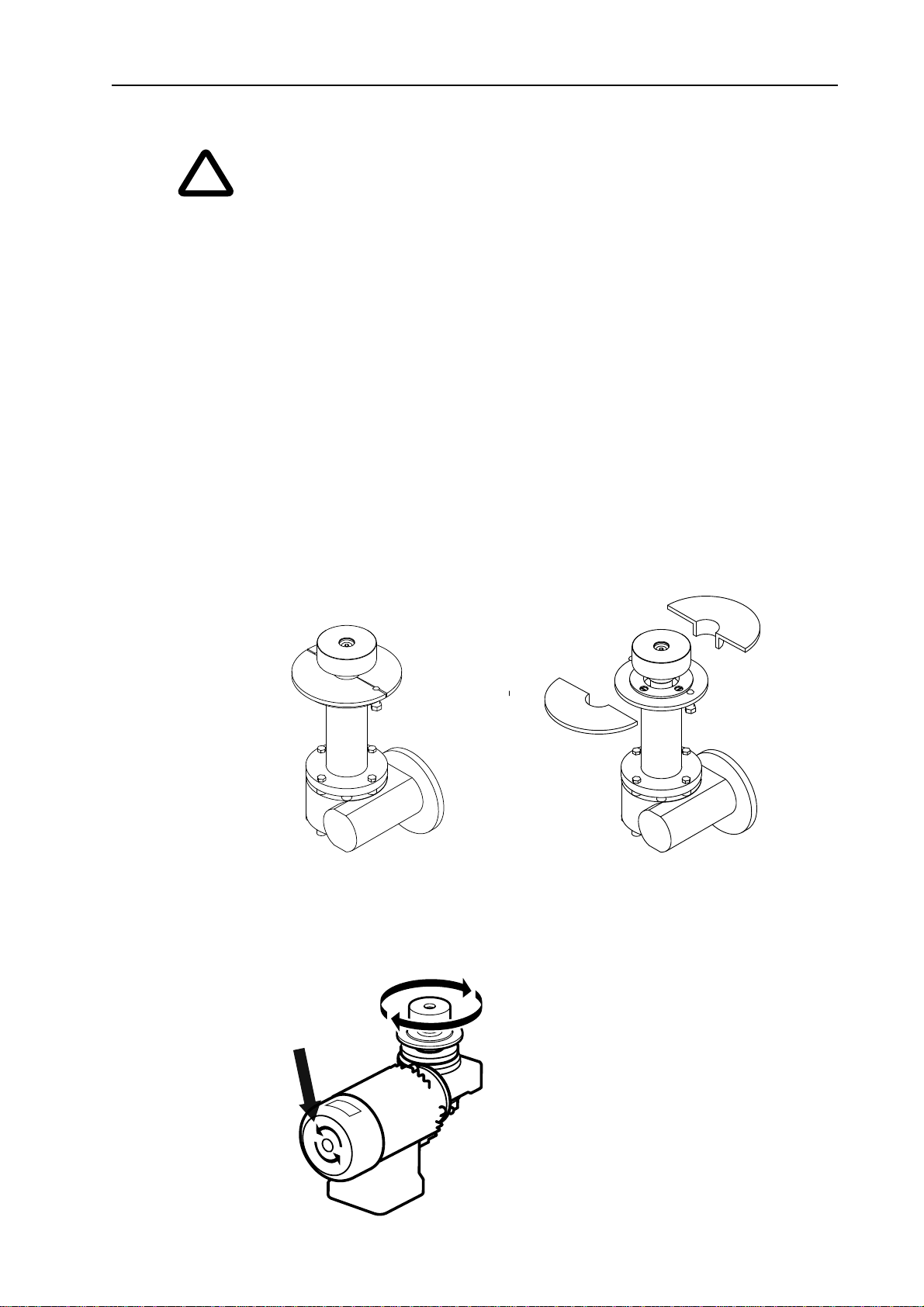
Drive Unit Installation
The drive unit may be heavy. Use appropriate equipment to avoid injury.•
Never use the drive unit without a frequency converter.•
See the Electrical Installation section of this user guide for electrical•
information.
Before installation:
Ensure that all incoming power is equipped with an emergency stop and an on/•
off switch that can be locked in both positions.
Ensure that the motor cables are shielded (to avoid disturbance).•
Ensure that the drive unit is properly grounded.•
Ensure that the electric cables are long enough so that the drive unit can be•
disassembled and removed from the vessel.
The mixing head must be covered with liquid before starting the unit.•
Store the motor in an area which is humid and weather proof. Ensure that•
motor is on a stable surface to prevent falling or vibration.
Remove the transport collar before installing the motor.•
Check Direction of Rotation
Turn on the motor. Verify that the outer drive head rotates clockwise and the fan
rotates counterclockwise.
A sticker on the motor indicates the correct rotation direction of the fan.
!
NovAseptic GMPATEX Mixer Installation and User Guide 19
Table of contents
Other Millipore Mixer manuals


