Millipore SDS 200 User manual

User Manual
SDS 200 - SDS 350


Notice
The information in this document is subject to change without notice and should not be construed as a commitment by Millipore
SAS. Millipore SAS assumes no responsibility for any errors that might appear in this document. This manual is believed to be
complete and accurate at the time of publication. In no event shall Millipore SAS be liable for incidental or consequential
damages in connection with or arising from the use of this manual.
We manufacture and sell water purification systems designed to produce pure or ultrapure water with specific characteristics
(µS/cm, T, TOC, CFU/ml, Eu/ml) when it leaves the water purification system provided that the systems are fed with water quality
within specifications, and properly maintained as required by the supplier.
We do not warrant these systems for any specific applications. It is up to the end user to determine if the quality of the water
produced by our systems matches his expectations, fits with norms/legal requirements and to bear responsibility resulting from
the usage of the water.
Copyright
2012 Millipore SAS. Printed in France. All rights reserved. This book or parts thereof may not be reproduced in any form
without the written permission of the publishers. The photos are non-contractual.
PF08837 - V3.0 – 12/2012
Manufacturer: MILLIPORE SAS, 67120 MOLSHEIM, FRANCE.
Trademarks
Elix is a registered trademark of Merck KGaA, Darmstadt, Germany.
RiOs, Merck Millipore and the M logo are trademarks of Merck KGaA, Darmstadt, Germany.
All other trademarks are trademarks of their respective owners.
Product warranty and limitation of liability
The applicable warranty and limitation of liability for the products listed in this publication may be found at
http://www.millipore.com/ec/cp3/terms within the "Terms and Conditions of Sale" applicable to your purchase transaction.
Recycling
Directive 2002/96 EC: For European users only
The symbol “crossed bin” on a product or its packaging indicates that the product should not be treated like
household waste when discarded. Instead the product should be disposed of at a location that handles
discarded electric or electronic equipment.
Proper disposal of equipment containing electric or electronic components will help to reduce pollution effects
to the environment or to human health. Proper recycling of these products helps in environmental
preservation and helps to protect natural resources. For more information about recycling of products
containing electric or electronic components, please contact your local recycling representative or
organization.
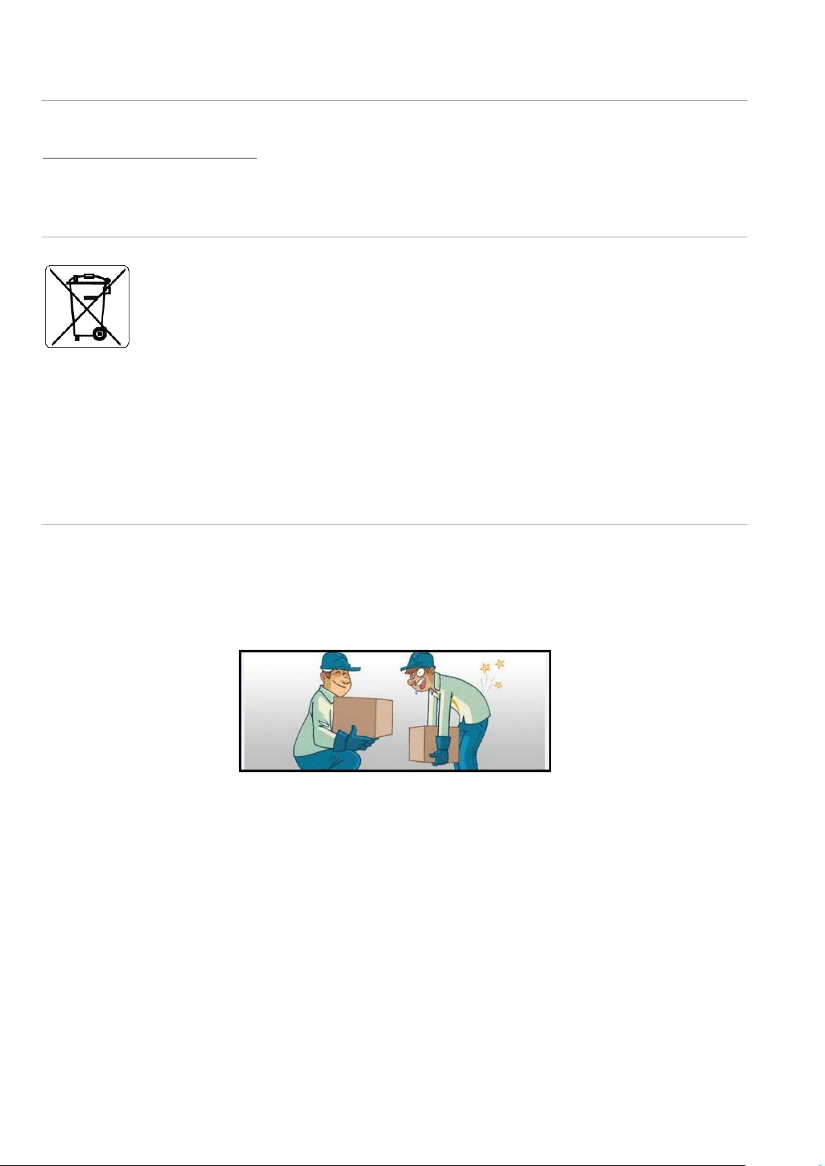
Use appropriate means for lifting and carrying.
Pay special attention to how you handle the system in order not to damage your back.
Lift by straightening your legs. Let your leg muscles, not your back muscles, do the work.

Table of Contents
CHAPTER 1INTRODUCTION ................................................................................................................................. 1
1-1 USING THIS MANUAL ..................................................................................................................................................................................................1
Matching this Manual with your Water System .................................................................................................................................................1
Installation Information..............................................................................................................................................................................................1
1-2 SAFETY INFORMATION .................................................................................................................................................................................................2
Safety Statement..........................................................................................................................................................................................................2
Safety Symbols ..............................................................................................................................................................................................................2
1-3 CONTACT MILLIPORE ...................................................................................................................................................................................................2
By Internet......................................................................................................................................................................................................................2
Manufacturing Site ......................................................................................................................................................................................................2
CHAPTER 2PRODUCT INFORMATION .................................................................................................................... 3
2-1 GENERAL DESCRIPTION ...............................................................................................................................................................................................3
Different Versions of SDS ...........................................................................................................................................................................................3
Standard SDS .................................................................................................................................................................................................................4
2-2 SCHEMATIC OF MAIN COMPONENTS...........................................................................................................................................................................5
2-3 THE FRONT PANEL .......................................................................................................................................................................................................6
2-4 TECHNICAL SPECIFICATIONS ........................................................................................................................................................................................6
Dimensions and Weight..............................................................................................................................................................................................6
Electrical Specifications..............................................................................................................................................................................................7
Environmental Specifications....................................................................................................................................................................................7
Hydraulic Specifications .............................................................................................................................................................................................7
Pump Performance .......................................................................................................................................................................................................8
CHAPTER 3USING THE SDS ............................................................................................................................... 9
3-1 DEFAULT SETTING ........................................................................................................................................................................................................9
3-2 PROGRAMMING THE SDS............................................................................................................................................................................................9
How to get in the DIST SETUP Mode.......................................................................................................................................................................9
What is the DIST MODE? .........................................................................................................................................................................................10
What is the DIST PROG? ..........................................................................................................................................................................................10
CHAPTER 4MAINTENANCE AND ALARMS ..........................................................................................................11
4-1 MAINTENANCE .........................................................................................................................................................................................................11
Maintenance Schedule.............................................................................................................................................................................................11
Sanitary Overflow Device ........................................................................................................................................................................................11
Sanitization of Reservoir .........................................................................................................................................................................................11
4-2 TROUBLESHOOTING GUIDE .......................................................................................................................................................................................11
CHAPTER 5ORDERING INFORMATION ................................................................................................................13
Catalogue Numbers for Consumables..................................................................................................................................................................13
CHAPTER 6APPENDIXES...................................................................................................................................15
APPENDIX 1MAIN FUSE REPLACEMENT ............................................................................................................................................................................15
APPENDIX 2CHECKLIST -WHAT’S INSIDE THE SHIPPING BOX.......................................................................................................................................... 16


Introduction
SDS 200 - SDS 350 1
Chapter 1 INTRODUCTION
1-1 USING THIS MANUAL
MATCHING THIS MANUAL WITH YOUR WATER SYSTEM
This manual is intended for use with a Millipore SAS SDS 200 or SDS 350.
This User Manual is a guide for use during the normal operation and maintenance of a SDS 200 or SDS 350 Water Storage and
Distribution System. It is highly recommended to completely read this manual and to fully comprehend its contents before
attempting normal operation or maintenance of the SDS.
If this manual is not the correct one for your SDS 200 or SDS 350, then please contact Millipore SAS.
INSTALLATION INFORMATION
IMPORTANT! INSTALLATION INSTRUCTIONS ARE NOT INCLUDED. INSTALLATION
OF THIS PRODUCT IS MEANT TO BE PERFORMED BY A QUALIFIED MILLIPORE SAS
SERVICE REPRESENTATIVE.
The Pre-Installation and Installation Documentation for the Water Systems
mentioned above are not found in this Manual. Contact Millipore SAS if you would
like to have this information.
Appendix 2 contains a Pre Installation Checklist. These can be used to confirm that you received the necessary items for
installation and also that the system was installed according to specifications.
ATTENTION
ATTENTION

Introduction
SDS 200 - SDS 350 2
1-2 SAFETY INFORMATION
SAFETY STATEMENT
Your Water System should be operated according to the instructions in this manual. In particular, the hydraulic and electrical
specifications should be followed and met. It is important to use this equipment as specified in this manual; using this equipment
in a different manner may impair the safety precautions of the Water System.
Do not open the system cabinet at any time. Electrical and mechanical components inside
the Water System could pose a hazard. A qualified Millipore SAS Service Representative
should perform any work that needs to be done while the system cabinet is opened.
SAFETY SYMBOLS
This
ATTENTION symbol is used to refer to instructions in this manual that need to
be done carefully.
These symbo
ls are used to indicate that proper safety equipment has to be used.
Protective glasses and gloves must be worn.
This
UV RADIATION sticker is used to refer to a position on the water system
Cabinet or inside of it where exposure to UV light is possible.
This
DANGER sticker is used to refer to a position on the water system Cabinet or
inside of it that could be hazardous.
This
ELECTRICAL GROUND
sticker is used to refer to a position on the water system
Cabinet or inside where an electrical ground co
nnection is made.
This
ELECTRICAL DANGER
sticker is used to refer to a position on the water system
Cabinet or inside where an electrical danger could exist.
1-3 CONTACT MILLIPORE SAS
For any questions or requests, please use the contact information provided below.
BY INTERNET
The Internet Site can be used to find addresses, telephone/fax numbers and other information.
Internet Site Address:
www.millipore.com
www.millipore.com/techservice
www.millipore.com/lab_water
MANUFACTURING SITE
Millipore SAS
67120 Molsheim
France
HAZARD

Product Information
SDS 200 - SDS 350 3
Chapter 2 PRODUCT INFORMATION
2-1 GENERAL DESCRIPTION
The SDS (Storage and Distribution System) has been developed for the purpose of storing purified water, and distributing it,
under pressure around a distribution loop. The purified water is generally produced by reverse osmosis or by continuous
deionisation.
DIFFERENT VERSIONS OF SDS
The table below shows the main components which come with the SDS.
COMPONENTS SDS TANK ALONE SDS WITH RELAY
(no pump) SDS WITH PUMP
Distribution Pump No No Yes
Power relay for pump/motor No Yes Yes
Back-pressure valve No No Yes
SDS level sensor No Yes Yes
Level Sensor Jack connector Mono Stereo Stereo
Pressure Gauge No No Yes

Product Information
SDS 200 - SDS 350 4
STANDARD SDS
The SDS with pump is shown below (front/back views):
Reservoir capacity
(200 or 350)
Vent filter
(to be ordered separately)
Plugged outlet
Pressure gauge
Reservoir access lid
Sanitary overflow
Front cabinet
Switch ON/OFF panel
Water level sensor
Isolating valve on feed
line to pump
Pump outlet
Drain tubing
Inlet fitting for purified water
Back pressure valve (on loop
return point)
Distribution pump
Draw off valve for complete
emptying of reservoir
Product Information
SDS 200 - SDS 350 5
Level sensor
Distribution pump
Sanitary
overflow
DRAIN
connection
Connected to a
water system
INLET
Distribution loop
return
Outward leg of
distribution loop
Reservoir
DRAIN
connection
BACK PRESSURE VALVE
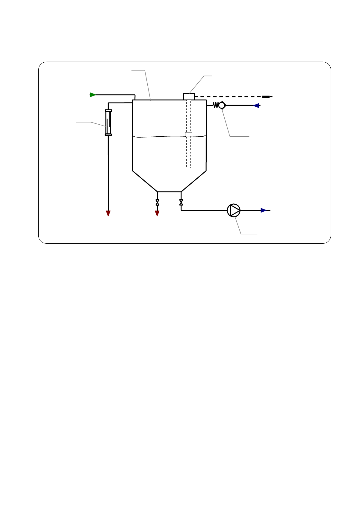
2-2 SCHEMATIC OF MAIN COMPONENTS
The water flow through the SDS is shown here in a flow diagram. A description of each item is below.
ITEM FUNCTION
Inlet Where purified water enters into the SDS.
Level sensor A device that measures the water level in the reservoir in % full, liters or gallons.
Sanitary overflow Where water goes if the SDS is filled beyond its capacity. The water is sent to drain.
Back pressure valve A valve that opens at a specific pressure thus creating a constant pressure in a distribution loop.
Distribution pump Used to pump water from the SDS to a distribution loop (standard version).
Product Information
SDS 200 - SDS 350 6
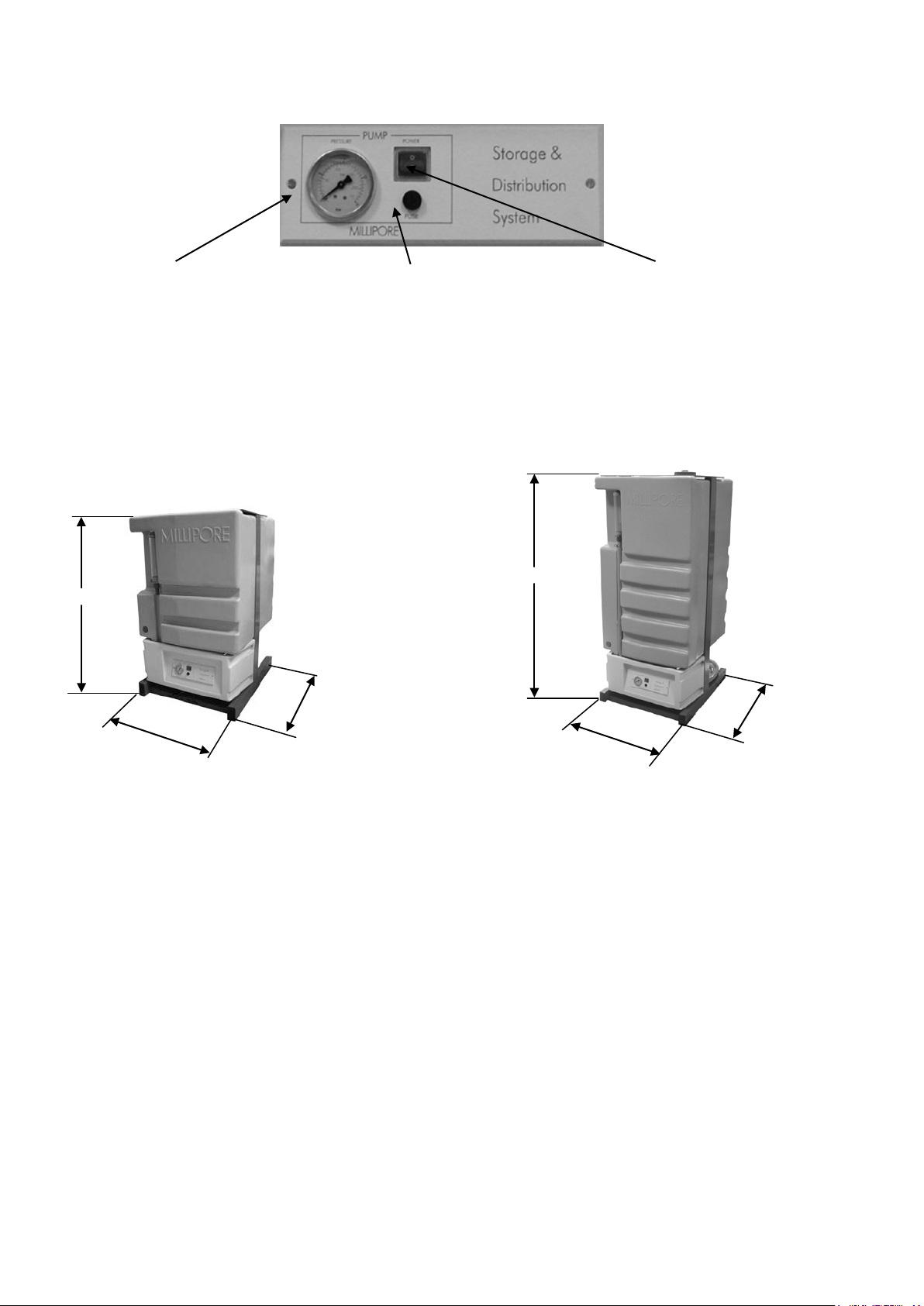
2-3 THE FRONT PANEL
PUMP PRESSURE
Pressure gauge showing pump outlet pressure.
FUSE HOLDER
Main fuse.
POWER ON/OFF
Main power switch.
2-4 TECHNICAL SPECIFICATIONS
DIMENSIONS AND WEIGHT
SDS 200
SDS 350
SDS 200 SDS 350
Operating weight 260 Kg 430 Kg
Dry weight 60 Kg 80 Kg
Shipping weight 72 Kg 95 Kg
1420 mm
600 mm
700 mm
1020 mm
600 mm
700 mm
Product Information
SDS 200 - SDS 350 7
ELECTRICAL SPECIFICATIONS
Voltage / Frequency / Power Cat. Number Main Fuse
100V ±10%/50-60 Hz/800 VA with pump TANK7P200
TANK7P350
10 A T fuse
Millipore SAS Spare Part FTPF04803
100V ±10%/50-60 Hz/10 VA without pump TANK70200
TANK70350
1 A F fuse
Millipore SAS Spare Part FTPF00756
120V ±10%/60Hz/800 VA with pump TANK6P200
TANK6P350
10 A T fuse
Millipore SAS Spare Part FTPF04803
120V ±10%/60Hz/10 VA without pump TANK60200
TANK60350
1 A F fuse
Millipore SAS Spare Part FTPF00756
230V ±10%/50Hz/800 VA with pump TANK5P200
TANK5P350
3.15 A T fuse
Millipore SAS Spare Part FTPF03213
230V ±10%/50Hz/10 VA without pump TANK50200
TANK50350
0.5 A T fuse
Millipore SAS Spare Part FTPF00306
The source of electrical power must be earth grounded.
ENVIRONMENTAL SPECIFICATIONS
Indoor use only.
Ambient storage temperature: 5°C< T <40°C
Altitude: < 3000 m
Installation Category: II
Pollution Degree: 2
HYDRAULIC SPECIFICATIONS
Purified water inlet to reservoir: 8 mm OD tubing
Distribution loop: inlet and return ¾inch NPT Male
Drain capacity (overflow): 220 LPH at a maximum height of 200 mm from floor level
Maximum length of drain tubing: 3 m

Using the SDS
SDS 200 - SDS 350 9
Chapter 3 USING THE SDS
3-1 DEFAULT SETTING
When using a SDS 200 or SDS 350 without pump, the default program setting is in the Water Purification System. It allows you
to run the SDS without any pre-settings during the Installation procedures. The SDS is a “plug and play” system device.
For a SDS with a pump, please read the procedures below for programming the pump running times.
3-2 PROGRAMMING THE SDS
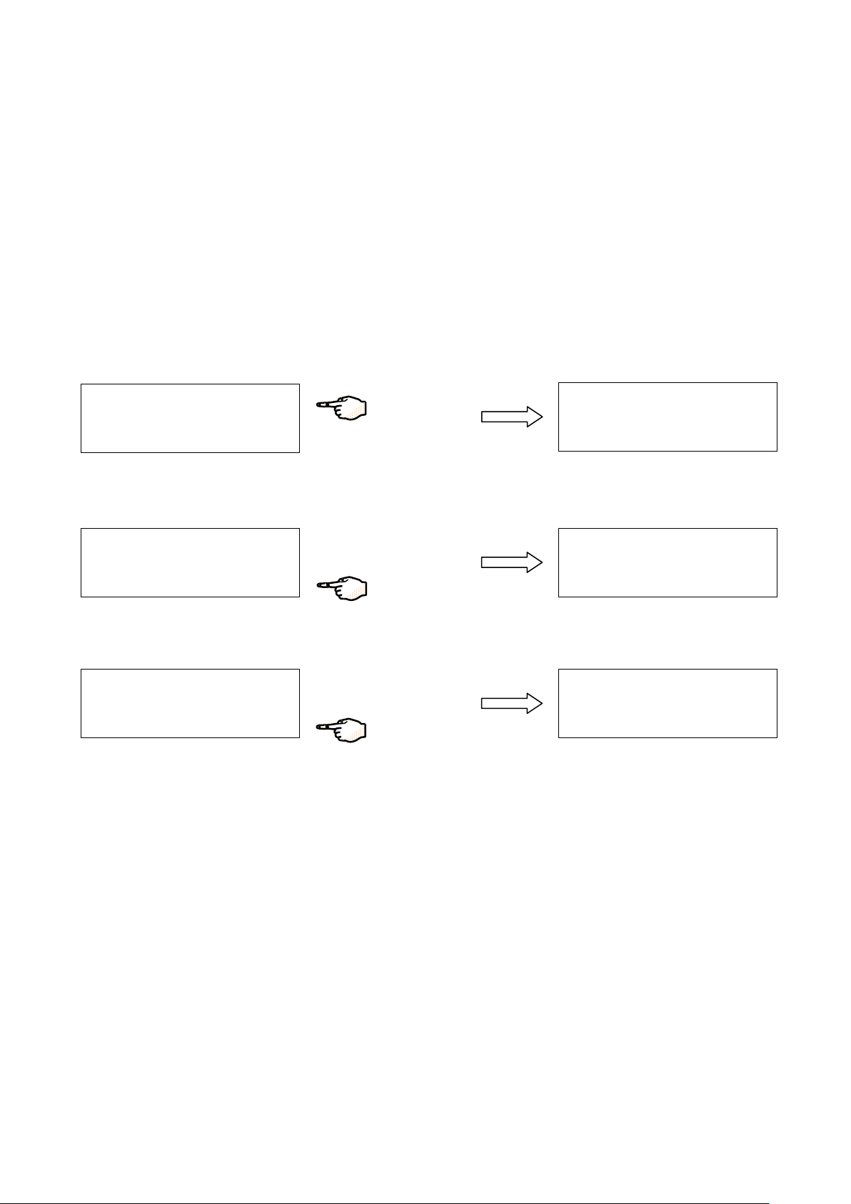
HOW TO GET IN THE DIST SETUP MODE
The DIST SETUP Menu shows you all the SDS functions.
S
T
A
N
D
B
Y
S
E
T
U
P
M
A
I
N
T
E
N
A
N
C
E
P
R
O
D
U
C
T
I
O
N
S
E
T
U
P
D
A
T
E
/
T
I
M
E
[
O
F
F
]
B
U
Z
Z
E
R
R
S
T
→
Press on SETUP. You are in SETUP Menu.
S
E
T
U
P
D
A
T
E
/
T
I
M
E
[
O
F
F
]
B
U
Z
Z
E
R
R
S
T
→
S
E
T
U
P
U
N
I T S
T
° C
O
M
P
→
Press on “”.
S
E
T
U
P
U
N
I T
S
T °
C
O
M
P
→
S
E
T
U
P
D
I S
T
M
O
D
E
D
I S
T
P
R
O
G
A
S
M
C
Y
C
L E
→
Press on “”. DIST SETUP Menu.

Using the SDS
SDS 200 - SDS 350 10
WHAT IS THE DIST MODE?
The DIST MODE allows you to activate, deactivate or program the recirculation.
S
E
T
U
P
D
I S
T
M
O
D
E
D
I S
T
P
R
O
G
A
S
M
C
Y
C
L E
→
D
I S
T
M
O
D
E
O
F
F
O
N
P
R
O
G
R
A
M
[
P
R
O
G
R
A
M
]
Press on DIST MODE.
The three functions in the DIST MODE are:
[OFF]: the DIST MODE is stopped (the pump is stopped).
[ON]: the DIST MODE is running permanently (the pump is running continuously).
[PROGRAM]: the DIST MODE is programmable for personal settings (see next section).
NOTE: the active mode can be visualized at the bottom of the LCD. For example, on the right display above, the [PROGRAM]
function is active.
WHAT IS THE DIST PROG?
You have put the DIST MODE into PROGRAM in the previous section. Now set the DIST PROG by choosing the DAY, the START
time, the STOP time and the duration of the RECIRC (recirculation).
S
E
T
U
P D
I S
T
M
O
D
E
D
I S
T
P
R
O
G
A
S
M
C
Y
C
L E
→
D
A
Y
:
A
L L D
A
Y
S
+
S
T
A
R
T
:
0
0
h
0
0
-
S
T
O
P
:
0
0
h
0
0
↔
R
E
C
I R
C
:
0
1
m
i n
/
h
Press on DIST PROG.
DAY Choose a specific day of a week (Monday, Tuesday, etc.) you want the DIST MODE to be effective.
Or choose All Days for all days of the week.
START Adjust the start hour and minutes.
STOP Adjust the stop hour and minutes.
RECIRC Set the recirculation duration to be executed automatically once in every hour (maximum 30 min every hour). If
the value is 0, there is no recirculation.
NOTE: the recirculation is used to maintain water quality in the distribution loop when the pump is not running.
Example: every Wednesday, the SDS pump is running continuously from 08h00
to 17h30. When the pump stops operating continuously, it will then be powered
for 30 minutes every hour between 17:30 and 08:00 the next day. This is what
happens during Recirculation Mode.
D
A
Y
:
W
E
D
N
E
S
D
A
Y
+
S
T
A
R
T
: 0
8
h
0
0
-
S
T
O
P
: 1
7
h
3
0
↔
R
E
C
I
R
C
: 3
0
m
i n
/
h
NOTE:
the SDS pump stops running automatically when the SDS is empty (below 0%) and does not restart until it is 10% full.

Troubleshooting
SDS 200 - SDS 350 11
Chapter 4 MAINTENANCE AND ALARMS
4-1 MAINTENANCE
MAINTENANCE SCHEDULE
What? When?
Replace Vent Filter (to be ordered separately) At the same time than the Progard Pak.
Fill the overflow with acid + pH indicator When the level of acid drops.
Sanitization of reservoir Contact Millipore SAS for an adapted sanitization protocol.
SANITARY OVERFLOW DEVICE
The SDS Overflow Device should be filled with water plus a germicidal agent. This prevents bacteria from growing in the Overflow
Device. One way to do this is to fill up the Overflow Device with an acidic solution. The instructions below provide information on
how to do this.
1. Make a Sulphuric Acid solution of pH 2 (equivalent to Normality 0.01 N). Add some pH indicator so a colour change can be
seen if the pH rises to a value such as 4. This will indicate that it is time to renew the acidic solution in the Overflow Device.
An indicator such as Methyl Orange can be used.
2. Locate the overflow device. Locate the red plug near the top of the Overflow Device.
3. Remove the red plug.
4. Inject some of the acidic solution into the Overflow Device. Replace the red plug
Acidic solutions can be dangerous if spilled on your skin or if it gets into your eyes. Wear eye protection
and wear gloves and other appropriate safety equipment while handling acid
SANITIZATION OF RESERVOIR
Contact Millipore SAS for an adapted sanitization protocol.
4-2 TROUBLESHOOTING GUIDE
All the displayed messages for the Maintenance and Alarms are described in the Water System User Manual.
!


Ordering Information
SDS 200 - SDS 350 13
Chapter 5 ORDERING INFORMATION
CATALOGUE NUMBERS FOR CONSUMABLES
ACCESSORIES DESCRIPTION CAT NUMBER
SDS-200 Tank 200L Tank only TANK00200
SDS-350 Tank 350L Tank only TANK00350
SDS tank RiOs vent filter 0.22 Aervent TANKVNT01
SDS tank Elix vent filter 0.22 Aervent, carbon and soda lime TANKVNT02
ASM Automatic Sanitization Module TANKASMUV
T
N
A
K
0 = without pump
P = with pump
200 = 200 L
350 = 350 L
0 = Tank only
5 = 230V/50Hz
6 = 120V/60Hz
7 = 100V/50-60Hz

This manual suits for next models
13
Table of contents
Popular Water Heater manuals by other brands


Amtrol
Amtrol HWBT120-2 Installation & operation instructions

Grundfos
Grundfos GT-CF Installation and operating instructions

A.O. Smith
A.O. Smith LTE 66D instruction manual

STIEBEL ELTRON
STIEBEL ELTRON DCE 3-1 Trend Operation and installation

Savio
Savio Laser 14 S Instruction manual for installation and use

Rinnai
Rinnai ByPass Servo troubleshooting manual

Webasto
Webasto Thermo Top E installation instructions

Kenmore
Kenmore 153.586420 Use & care guide

Kohler
Kohler HYDRO-TOWER 300 K-4178T installation instructions

A.O. Smith
A.O. Smith ZIP user manual

A.O. Smith
A.O. Smith FPD SEALED SHOT owner's manual

Takagi
Takagi T?KJr2?IN Installation manual and owner's guide