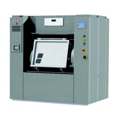
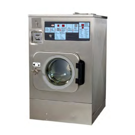
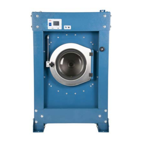
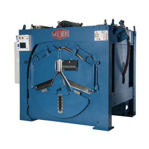
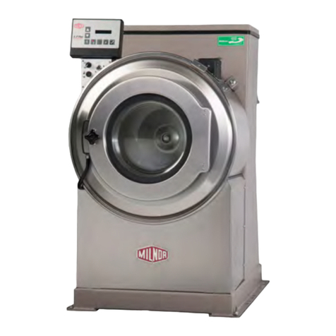
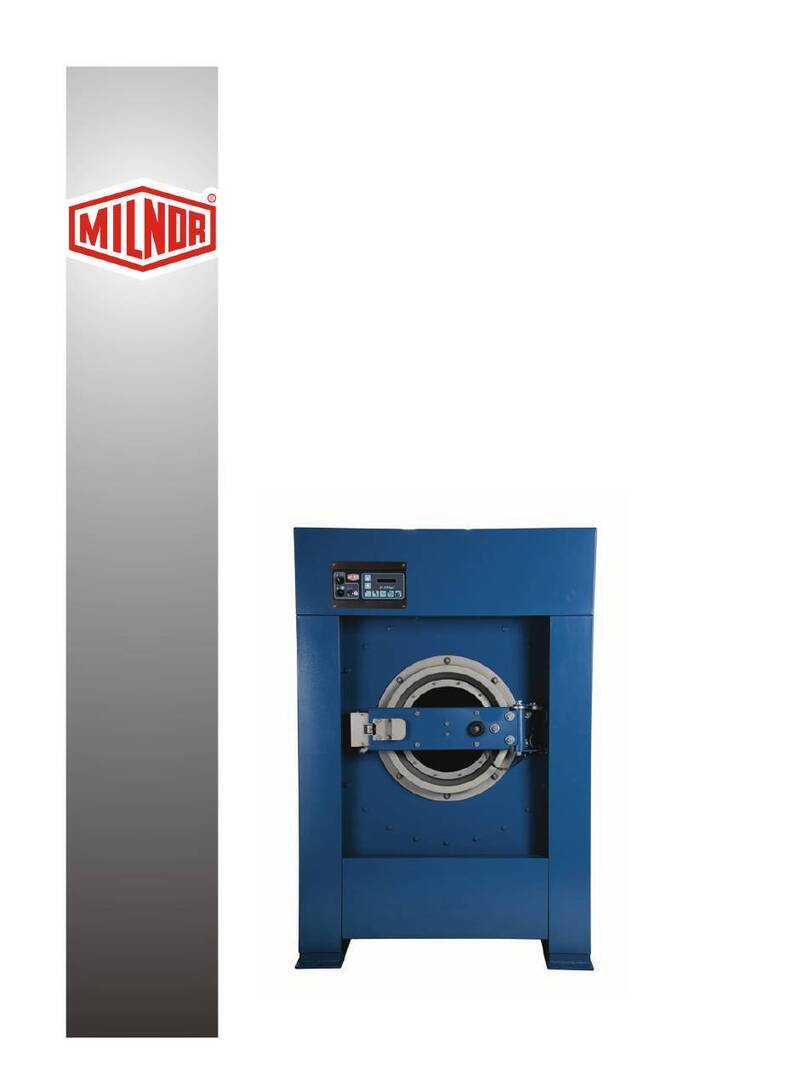
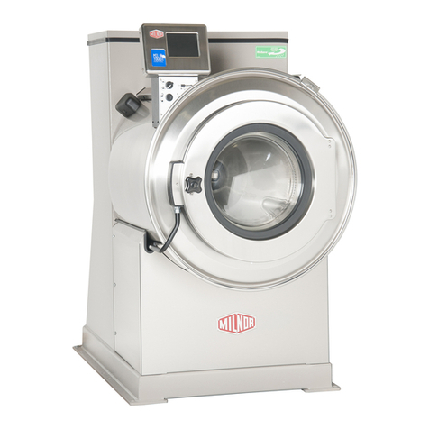
Milnor 36021V5J User manual

PELLERIN MILNOR CORPORATION Post Office Box 400, Kenner, Louisiana 70063–0400, U.S.A.
Installation
36021 & 36026V5J/
V5Z; 36021 &
36026V7Z; 42026V5J/
V6Z; 42030V6Z
Manual Number: MCWOBI01
Edition (ECN): 2023313


Pellerin Milnor Corporation i
Contents
1 General Information ......................................................................................................................4
Limited Standard Warranty .....................................................................................................5
How to Get the Necessary Repair Components ......................................................................6
Trademarks ..............................................................................................................................6
Safety — Rigid Washer Extractors ..........................................................................................7
Safety Alert Messages—Internal Electrical and Mechanical Hazards.............................7
Safety Alert Messages—Cylinder and Processing Hazards.............................................7
Safety Alert Messages—Unsafe Conditions ....................................................................8
Damage and Malfunction Hazards ...........................................................................8
Hazards Resulting from Inoperative Safety Devices........................................8
Hazards Resulting from Damaged Mechanical Devices ..................................9
Careless Use Hazards .............................................................................................10
Careless Operation Hazards—Vital Information for Operator Personnel
(see also operator hazards throughout manual) ..............................10
Careless Servicing Hazards—Vital Information for Service Personnel
(see also service hazards throughout manuals) ..............................10
Installation Tag Guidelines ....................................................................................................11
2 Important Installation Precautions...............................................................................................14
External Fuse/Breaker, Wiring, and Disconnect Requirements ............................................14
Fuse or Circuit Breaker Size...........................................................................................14
• If a fuse is used....................................................................................................14
• If a standard circuit breaker is used ....................................................................14
• If an inverse time circuit breaker is used ............................................................14
Wire Size ........................................................................................................................14
Ground............................................................................................................................15
Disconnect Switch for Lockout/Tagout..........................................................................15
Using GFCI (Ground Fault Circuit Interrupter) Device.................................................15
Vital Information About the Forces Imparted to Supporting Structures by Laundering
Machines ................................................................................................................15
Disclaimer of Responsibility ..........................................................................................16
Major Design Considerations .........................................................................................16
Primary Information Sources .........................................................................................17
Prevent Damage from Chemical Supplies and Chemical Systems .......................................17
How Chemical Supplies Can Cause Damage.................................................................18
• Dangerous Chemical Supplies and Wash Formulas............................................18
• Incorrect Configuration or Connection of Equipment ........................................18
Equipment and Procedures That Can Prevent Damage..................................................20
• Use the chemical manifold supplied. ..................................................................20
• Close the line.......................................................................................................21
• Do not let a vacuum occur...................................................................................21
• Flush the chemical tube with water.....................................................................21
• Put the chemical tube fully below the inlet.........................................................21
• Prevent leaks. ......................................................................................................21
3 Installation Procedures ................................................................................................................22
Handling a Washer-extractor from Delivery to Final Location .............................................22
Notices............................................................................................................................22

ii Pellerin Milnor Corporation
• Qualified Personnel Only....................................................................................22
• Disclaimer ...........................................................................................................22
• Other Tasks .........................................................................................................22
Facility Prerequisites ......................................................................................................23
Rigger Precautions..........................................................................................................23
Technician Precautions...................................................................................................25
• Can the Door(s) Be Opened Before Utilities are Connected? ............................27
Connection Precautions for Washer-extractors .....................................................................27
Notices............................................................................................................................28
• Machine Must Be Anchored ...............................................................................28
Utility Requirements and Related Information ..............................................................28
Plumber Precautions.......................................................................................................29
Electrician Precautions ...................................................................................................30
Chemical Supplier Precautions.......................................................................................31
4 Dimensional Drawings ................................................................................................................32
BD3621V5JAE/2022252 — 36021V5J ................................................................................33
BD3621V5JAB/2022252 — 36021V5J (Options) ................................................................34
BD3621V5ZBE/2015462 – 36021V5Z .................................................................................35
BD3621V5ZBB/2020034 – 36021V5Z Options ...................................................................36
BD3621V7ZBE/2017134 – 36021V7Z .................................................................................37
BD3621V7ZBB/2020034 – 36021V7Z Options ...................................................................38
BD3626V5JAE/2022252 — 36026V5J ................................................................................39
BD3626V5JAB/2022252 — 36026V5J (Options) ................................................................40
BD3626V5ZBE/2021103 – 36026V5Z .................................................................................41
BD3626V5ZBB/2020034 – 36026V5Z Options ...................................................................42
BD3626V7ZBE/2017134 – 36026V7Z .................................................................................43
BD3626V7ZBB/2020034 – 36026V7Z Options ...................................................................44
BD4226V5JAE/2022252 — 42026V5J ................................................................................45
BD4226V5JAB/2022252 — 42026V5J (Options) ................................................................46
BD4226V6ZBE/2022424 – 42026V6Z .................................................................................47
BD4226V6ZBB/2020034 – 42026V6Z Options ...................................................................48
BD4230V6ZBE/2019416 – 42030V6Z .................................................................................49
BD4230V6ZBB/2020034 – 42030V6Z Options ...................................................................50
5 Dimensional Drawings: Pedestals ...............................................................................................51
BD36V5BSBE/2013063 — 36021/36026V5J, V5Z (Pedestal) ............................................53
BD42V6BSAE/2013064 — 3621/3626V7J, V7Z; 4226/4230V6J, V6Z (Pedestal) ............54
Figures
Figure 1 How Rotating Forces Act On the Foundation ..........................................................17
Figure 2 Incorrect Configurations That Let the Chemical Supply Go In the Ma-
chine by a Siphon......................................................................................................19
Figure 3 Incorrect Configurations That Let the Chemical Supply Go In the Ma-
chine by Gravity........................................................................................................20
Figure 4 Examples of Manifolds for Chemical Tubes. Your equipment can look
different.....................................................................................................................20
Figure 5 A Configuration that Prevents Flow in the Machine When the Pump is
Off (if the chemical tube and tank have no pressure) ...............................................21
Contents

4Pellerin Milnor Corporation
1 General Information

6Pellerin Milnor Corporation
BNUUUM01 / 2019342 BNUUUM01 0000250121 B.3 1/2/20, 2:14 PM Released
How to Get the Necessary Repair Components
BNUUUM01.C01 0000250120 C.4 B.3 A.3 1/2/20, 2:14 PM Released
You can get components to repair your machine from the approved supplier where you got this
machine. Your supplier will usually have the necessary components in stock. You can also get
components from the Milnor®factory.
Tell the supplier the machine model and serial number and this data for each necessary
component:
• The component number from this manual
• The component name if known
• The necessary quantity
• The necessary transportation requirements
• If the component is an electrical component, give the schematic number if known.
• If the component is a motor or an electrical control, give the nameplate data from the used
component.
To write to the Milnor®factory:
Pellerin Milnor Corporation
Post Office Box 400
Kenner, LA 70063-0400
UNITED STATES
Telephone: 504-712-7775
Fax: 504-469-9777
Email: parts@milnor.com
BNUUUU02 / 2023296 BNUUUU02 0000158094 G.2 7/20/23, 10:58 AM Released
Trademarks BNUUUU02.R01 0000158093 C.4 G.2 F.2 7/20/23, 10:57 AM Released
These words are trademarks of Pellerin Milnor®Corporation and other entities:
Table 1. Trademarks
AutoSpot™ GreenFlex™ MilMetrix®PulseFlow®
CBW®GearTrace™ MilTouch™ RAM Command™
Drynet™ GreenTurn™ MilTouch-EX™ RecircONE®
E-P Express®Hydro-cushion™ MilRAIL®RinSave®
E-P OneTouch®Mentor®Miltrac™ SmoothCoil™
General Information

Pellerin Milnor Corporation 7
Table 1 Trademarks (cont'd.)
E-P Plus®Mildata®MilVision™ Staph Guard®
Gear Guardian®Milnor®PBW™
BNWRUS08 / 2019335 BNWRUS08 0000249979 B.3 1/2/20, 2:19 PM Released
Safety — Rigid Washer Extractors
BNWRUS08.C01 0000249978 C.4 B.3 A.3 1/2/20, 2:19 PM Released
Safety Alert Messages—Internal Electrical and Mechanical
Hazards BNWRUS01.C03 0000234538 C.4 B.3 A.6 1/2/20, 2:19 PM Released
The following are instructions about hazards inside the machine and in electrical enclosures.
WARNING: Electrocution and Electrical Burn Hazards — Contact with electric
power can kill or seriously injure you. Electric power is present inside the
cabinetry unless the main machine power disconnect is off.
�Do not unlock or open electric box doors.
�Do not remove guards, covers, or panels.
�Do not reach into the machine housing or frame.
�Keep yourself and others off of machine.
�Know the location of the main machine disconnect and use it in an emergency to re-
move all electric power from the machine.
WARNING: Entangle and Crush Hazards — Contact with moving components nor-
mally isolated by guards, covers, and panels, can entangle and crush your
limbs. These components move automatically.
�Do not remove guards, covers, or panels.
�Do not reach into the machine housing or frame.
�Keep yourself and others off of machine.
�Know the location of all emergency stop switches, pull cords, and/or kick plates and
use them in an emergency to stop machine motion.
Safety Alert Messages—Cylinder and Processing Hazards
BNWRUS03.C03 0000234586 C.4 B.3 A.4 1/2/20, 2:19 PM Released
The following are instructions about hazards related to the cylinder and laundering process.
DANGER: Entangle and Sever Hazards — Contact with goods being processed can
cause the goods to wrap around your body or limbs and dismember you.
The goods are normally isolated by the locked cylinder door.
�Do not attempt to open the door or reach into the cylinder until the cyl-
inder is stopped.
General Information

8Pellerin Milnor Corporation
�Do not touch goods inside or hanging partially outside the turning cylinder.
�Do not operate the machine with a malfunctioning door interlock.
�Know the location of all emergency stop switches, pull cords, and/or kick plates and
use them in an emergency to stop machine motion.
�Know the location of the main machine disconnect and use it in an emergency to re-
move all electric power from the machine.
WARNING: Crush Hazards — Contact with the turning cylinder can crush your limbs.
The cylinder will repel any object you try to stop it with, possibly causing
the object to strike or stab you. The turning cylinder is normally isolated
by the locked cylinder door.
�Do not attempt to open the door or reach into the cylinder until the cyl-
inder is stopped.
�Do not place any object in the turning cylinder.
�Do not operate the machine with a malfunctioning door interlock.
WARNING: Confined Space Hazards — Confinement in the cylinder can kill or injure
you. Hazards include but are not limited to panic, burns, poisoning, suffo-
cation, heat prostration, biological contamination, electrocution, and
crushing.
�Do not attempt unauthorized servicing, repairs, or modification.
WARNING: Explosion and Fire Hazards — Flammable substances can explode or
ignite in the cylinder, drain trough, or sewer. The machine is designed for
washing with water, not any other solvent. Processing can cause solvent-
containing goods to give off flammable vapors.
�Do not use flammable solvents in processing.
�Do not process goods containing flammable substances. Consult with
your local fire department/public safety office and all insurance providers.
Safety Alert Messages—Unsafe Conditions
BNWRUS04.C01 0000234585 C.4 B.3 A.3 1/2/20, 2:19 PM Released
Damage and Malfunction Hazards
BNWRUS04.C02 0000234584 C.4 B.3 A.3 1/2/20, 2:19 PM Released
Hazards Resulting from Inoperative Safety Devices
BNWRUS04.C03 0000234583 C.4 B.3 B.4 1/2/20, 2:19 PM Released
DANGER: Entangle and Sever Hazards — Cylinder door interlock—Operating the
machine with a malfunctioning door interlock can permit opening the door
when the cylinder is turning and/or starting the cycle with the door open,
exposing the turning cylinder.
�Do not operate the machine with any evidence of damage or
malfunction.
General Information

Pellerin Milnor Corporation 9
WARNING: Multiple Hazards — Operating the machine with an inoperative safety
device can kill or injure personnel, damage or destroy the machine, dam-
age property, and/or void the warranty.
�Do not tamper with or disable any safety device or operate the machine with a mal-
functioning safety device. Request authorized service.
WARNING: Electrocution and Electrical Burn Hazards — Electric box doors—Op-
erating the machine with any electric box door unlocked can expose high
voltage conductors inside the box.
�Do not unlock or open electric box doors.
WARNING: Entangle and Crush Hazards — Guards, covers, and panels—Operating
the machine with any guard, cover, or panel removed exposes moving
components.
�Do not remove guards, covers, or panels.
Hazards Resulting from Damaged Mechanical Devices
BNWRUS04.C04 0000234652 C.4 B.3 B.2 1/2/20, 2:19 PM Released
WARNING: Multiple Hazards — Operating a damaged machine can kill or injure per-
sonnel, further damage or destroy the machine, damage property, and/or
void the warranty.
�Do not operate a damaged or malfunctioning machine. Request authorized service.
WARNING: Explosion Hazards — Cylinder—A damaged cylinder can rip apart dur-
ing extraction, puncturing the shell and discharging metal fragments at
high speed.
�Do not operate the machine with any evidence of damage or
malfunction.
WARNING: Explosion Hazards — Clutch and speed switch (multiple motor ma-
chines)—A damaged clutch or speed switch can permit the low speed mo-
tor to engage during extract. This will over-speed the motor and pulleys
and can cause them to rip apart, discharging metal fragments at high speed.
�Stop the machine immediately if any of these conditions occur: • ab-
normal whining sound during extract • skidding sound as extract ends •
clutches remain engaged or re-engage during extract
General Information

10 Pellerin Milnor Corporation
Careless Use Hazards BNWRUS04.C05 0000234651 C.4 B.3 A.2 1/2/20, 2:19 PM Released
Careless Operation Hazards—Vital Information for Operator Personnel (see also
operator hazards throughout manual)
BNWRUS04.C06 0000234650 C.4 B.3 A.3 1/2/20, 2:19 PM Released
WARNING: Multiple Hazards — Careless operator actions can kill or injure person-
nel, damage or destroy the machine, damage property, and/or void the
warranty.
�Do not tamper with or disable any safety device or operate the machine with a mal-
functioning safety device. Request authorized service.
�Do not operate a damaged or malfunctioning machine. Request authorized service.
�Do not attempt unauthorized servicing, repairs, or modification.
�Do not use the machine in any manner contrary to the factory instructions.
�Use the machine only for its customary and intended purpose.
�Understand the consequences of operating manually.
Careless Servicing Hazards—Vital Information for Service Personnel (see also
service hazards throughout manuals)
BNWRUS04.C07 0000234649 C.4 B.3 A.3 1/2/20, 2:19 PM Released
WARNING: Electrocution and Electrical Burn Hazards — Contact with electric
power can kill or seriously injure you. Electric power is present inside the
cabinetry unless the main machine power disconnect is off.
�Do not service the machine unless qualified and authorized. You must
clearly understand the hazards and how to avoid them.
�Abide by the current OSHA lockout/tagout standard when lockout/tag-
out is called for in the service instructions. Outside the USA, abide by the OSHA standard
in the absence of any other overriding standard.
WARNING: Entangle and Crush Hazards — Contact with moving components nor-
mally isolated by guards, covers, and panels, can entangle and crush your
limbs. These components move automatically.
�Do not service the machine unless qualified and authorized. You must
clearly understand the hazards and how to avoid them.
�Abide by the current OSHA lockout/tagout standard when lockout/tag-
out is called for in the service instructions. Outside the USA, abide by the OSHA standard
in the absence of any other overriding standard.
WARNING: Confined Space Hazards — Confinement in the cylinder can kill or injure
you. Hazards include but are not limited to panic, burns, poisoning, suffo-
cation, heat prostration, biological contamination, electrocution, and
crushing.
�Do not enter the cylinder until it has been thoroughly purged, flushed,
drained, cooled, and immobilized.
General Information

Pellerin Milnor Corporation 11
BNWOAI01 / 2023306 BNWOAI01 0000170412 C.2 7/28/23, 3:47 PM Released
Installation Tag Guidelines
BNWOAI01.R01 0000187126 C.4 C.2 B.2 7/28/23, 3:47 PM Released
36021V5J 36021V5Z 36021V7Z 36026V5J
36026V5Z 36026V7Z 42026V5J 42026V6Z
42030V6Z
NOTICE: This information may apply to models in addition to those listed above. It ap-
plies to paper tags. It does not apply to the vinyl or metal safety placards, which must re-
main permanently affixed to the machine and replaced if no longer readable.
Paper tags on the machine provide installation guidelines and precautions. The tags can be tie-on
or adhesive. You can remove tie-on tags and white, adhesive tags after installation. Yellow adhe-
sive tags must remain on the machine.
The following entries explain the installation tags. Each entry includes: 1) the tag illustration, 2)
the tag part number at the bottom of the tag, and 3) the meaning of the tag.
Symbol Explanation
Read the manuals before proceeding. This symbol appears on
most tags. The machine ships with safety, operator, and routine
maintenance guides for customer use. Milnor dealer manuals for
installing, commissioning, and servicing the machine are also
available from the Milnor Parts department.
B2TAG88005: This carefully built product was tested and in-
spected to meet Milnor performance and quality standards by
(identification mark of tester).
B2TAG93013: This bearing housing was lubricated at the Milnor
factory before shipment. (Only used on 36” V models. Not used
on 42” V models.)
B2TAG94078: Do not forklift here; do not jack here; do not step
here—whichever applies.
B2TAG94081: Motor must rotate in this direction. On single mo-
tor washer-extractors and centrifugal extractors, the drive motor
must turn in this direction during draining and extraction. This tag
is usually wrapped around a motor housing. If the motor turns in
the opposite direction when the machine is first tested, the electri-
cal hookup is incorrect and must be reversed as explained in the
schematic manual.
General Information

12 Pellerin Milnor Corporation
B2TAG94097: The cylinder must rotate counterclockwise during
draining and extraction (spin) when viewed from here (rear of ma-
chine). Otherwise, reverse the electric power connections, as ex-
plained in the schematic manual.
B2TAG94099: Do not strike the shell door when fork-lifting. This
can cause the door to leak.
B2T2001013: Hot water connection.
B2T2001014: Cold water connection.
B2T2001015: Reuse (third) water connection. (Optional)
B2T2001028: Look for tags inside the machine. These tags may
identify shipping restraints to be removed or components to be in-
stalled. Do not start the machine until these actions are completed.
B2T2002013: Do not start the machine until shipping restraints
are removed. This tag will appear on the outside of the machine to
alert you to the presence of internal shipping restraints. A tag will
also appear on the restraint to help identify it. Most, but not all
shipping restraints display the color red. Some shipping restraints
are also safety stands. Do not discard these.
General Information

14 Pellerin Milnor Corporation
2 Important Installation Precautions
BFUUUF01 / 2023174 BNUUUF01 0000109243 D.2 4/26/23, 10:44 AM Released
External Fuse/Breaker, Wiring, and Disconnect
Requirements
BNUUUF01.C01 0000109242 C.4 D.2 A.4 1/2/20, 2:14 PM Released
An external fuse or circuit breaker and a disconnect switch must be provided in the facility for
(and dedicated to) the machine. These may be in the same or separate, permanently mounted
electric boxes. Electric power and ground connections will be made between the incoming power
junction box on the machine and this external box (or one of the boxes).
Fuse or Circuit Breaker Size BNUUUF01.R01 0000109241 C.4 D.2 A.4 1/2/20, 2:14 PM Released
Refer to the “External Fuse and Wire Sizes...” document for your machine model. This document
will be found in the machine's installation manual, available from the parts department. Choose
the fuse or circuit breaker from the appropriate column of the table provided, as follows:
If a fuse is used — Match the fuse listed in the “Fuse” column for your machine's voltage.
The specified fuse sizes are consistent with the USA National Electric Code (NEC), section 430-
52, exception No. 2, Part B, which states: “The rating of a time-delay (dual-element) fuse shall be
permitted to be increased, but shall in no case exceed 225 percent of the full-load current.”
If a standard circuit breaker is used — Match the amperage rating listed in the
“Breaker” column for your machine's voltage.
If an inverse time circuit breaker is used — Match the characteristics (amperage
rating) of the fuse listed in the “Fuse” column for your machine's voltage. When applied to an in-
verse time circuit breaker, the specified fuse sizes are consistent with the USA National Electric
Code (NEC), section 430-52, exception No. 2, Part C, which states: “The rating of an inverse time
circuit breaker shall be permitted to be increased, but shall in no case exceed 400 percent for full-
load currents of 100 amperes or less.”
Wire Size BNUUUF01.R02 0000109240 C.4 D.2 A.4 1/2/20, 2:14 PM Released
Use wiring no smaller than that listed for your machine's voltage in the “Wire size... ”column in
the “External Fuse and Wire Sizes...” document. The table value applies to runs up to 50 feet (15
meters). Use the next larger size for runs 50 to 100 feet (15 to 30 meters). Use wire two sizes larg-
er for runs greater than 100 feet (30 meters). If an inverse time circuit breaker is used and local
codes require a larger wire size than that specified by Milnor, abide by the local code.

Pellerin Milnor Corporation 15
NOTICE: The specified wire size may appear too small for the fuse or circuit breaker
shown. However, it is consistent with both the load imposed and with the USA National
Electric Code.
Ground BNUUUF01.R03 0000109239 C.4 D.2 A.4 1/2/20, 2:14 PM Released
The ground wire and connections must ensure a reliable earth ground (zero potential). Use wiring
of at least as large a gauge as that required for incoming power. Do not rely on conduit, machine
anchorage, etc. Use the ground lug provided in the incoming power junction box on the machine.
Disconnect Switch for Lockout/Tagout
BNUUUF01.R04 0000109238 C.4 D.2 A.5 1/2/20, 2:14 PM Released
The disconnect switch must permit personnel to disconnect and lockout/tagout electric power
from the machine. In the USA, refer to OSHA standard 1910.147 “The control of hazardous en-
ergy (lockout/tagout)”. Refer to the USA National Electric Code for requirements on locating the
switch. In other locales, abide by these standards if no other local codes apply.
Using GFCI (Ground Fault Circuit Interrupter) Device
BNUUUF01.R05 0000571262 C.4 D.2 A.2 4/26/23, 10:44 AM Released
The AC Drive will most likely cause the GFCI protection device to trip. The reason the AC Drive
will cause this tripping of the GFCI is the Common Mode Current or Common Mode Noise (CM
Noise) that the VFD is producing.
Use a GFCI with a higher trip level.
NOTE: Choose a GFCI designed specifically for an AC drive. The operation time
should be at least 0.1 s with sensitivity amperage of at least 200 mA per drive. The output
waveform of the drive may cause an increase in leakage current. This may in turn cause
the leakage breaker to malfunction. Increase the sensitivity amperage or lower the carrier
frequency to correct the problem.
Use a type B GFCI according to IEC/EN 60755.
BNUUUI01 / 2019392 BNUUUI01 0000189337 C.3 1/2/20, 2:14 PM Released
Vital Information About the Forces Imparted to Sup-
porting Structures by Laundering Machines
BNUUUI01.C01 0000189336 C.4 C.3 A.5 1/2/20, 2:14 PM Released
This document replaces Milnor®document BIWUUI02.
All laundering machines impart static and dynamic forces to the supporting structures (foundation
and soil, floor, and building). Static forces include the machine weight plus the weight of the
goods and water. Dynamic forces are those imparted by various machine movements as explained
in Section : Major Design Considerations, page 16. The dynamic forces imparted to supporting
structures can cause vibration and noise outside of the laundry room if supporting structures are
inadequate.
Important Installation Precautions

16 Pellerin Milnor Corporation
Disclaimer of Responsibility
BNUUUI01.C02 0000189359 C.4 C.3 B.3 1/2/20, 2:14 PM Released
Pellerin Milnor Corporation accepts no responsibility for damage or loss as a result of:
• inadequate supporting structures
• interference with the use of the facility caused by machine operation
The facility owner/operator is solely responsible to ensure that:
• supporting structures are strong enough, with a reasonable safety factor, to safely support the
operating machine or group of machines
• supporting structures are rigid enough to isolate vibrations and noise to the laundry room
If the owner/operator does not possess the necessary expertise to ensure that the facility can safely
and functionally accommodate the equipment, it will be necessary to consult the appropriate ex-
pert(s), such as a structural engineer, soils engineer, and/or architect.
Major Design Considerations
BNUUUI01.C03 0000189358 C.4 C.3 A.5 1/2/20, 2:14 PM Released
• Vibration and/or noise can be felt or heard outside of the laundry room as a result of the fol-
lowing, if supporting structures are not sufficiently rigid:
– Extraction (the spinning cylinder) in washer-extractors and centrifugal extractors, imparts
sinusoidal forces to supporting structures as shown in Figure 1: How Rotating Forces Act
On the Foundation, page 17 . In rigid washer-extractors, these forces are up to 30 times
that of suspended washer-extractors of the same capacity.
– Extraction forces can be magnified many times if the rotation frequency matches the reso-
nant frequency of supporting structures. To avoid this, supporting structures must have a
natural resonant frequency many times greater than any possible rotation speed of the ma-
chine or combination of rotation speeds of all machines.
– Each time goods fall in the rotating cylinder of a washer, washer-extractor, centrifugal ex-
tractor, or dryer, this can impart a force to the supporting structures.
– The intermittent start and stop actions of large components inside the machine, particu-
larly in a tilting washer-extractor, press-extractor, or centrifugal extractor, can impart in-
termittent forces to the supporting structures.
• The possibility of adverse consequences is significantly greater for upper floor installations
than for installations at grade. Always consult a structural engineer for such an installation.
• The possibility of adverse consequences is significantly greater for installations at grade if
subsidence causes a void between the foundation and the soil or if the soil itself does not pro-
vide adequate strength and rigidity. Some possible remedies are the addition of pilings or a
deeper foundation, installed as to be monolithic with the existing foundation.
• Machine forces can cause damage to the machine or the floor without the correct anchorage.
• Applicable building codes, even when met, do not guarantee sufficient structural support and
isolation of machine forces to the laundry room.
Important Installation Precautions

Pellerin Milnor Corporation 17
Figure 1. How Rotating Forces Act On the Foundation
Typical Washer-extractor (see note below)
Legend
A...Direction of force
B...Load
C...Rotation (frequency = RPM / 60)
NOTE: This figure applies to both rigid and suspended washer-extractors and to both
at-grade and upper floor installations.
Primary Information Sources
BNUUUI01.C04 0000189357 C.4 C.3 A.5 1/2/20, 2:14 PM Released
Milnor®provides, or can provide the following information of use to engineers and architects, for
the given machine model:
• The machine dimensional drawing, found in the installation manual, specifies the machine’s
required anchorage.
• The Milnor®Service Department can provide static and dynamic load values and frequency
(extract speed) values on request.
NOTICE: All data is subject to change without notice and may have changed since last
printed. It is the responsibility of the potential owner/operator to obtain written confirma-
tion that any data furnished by Milnor®applies for the model number(s) and serial num-
ber(s) of the purchased machine(s).
BIWUUI03 / 2019296 BNUUUR02 0000160550 E.3 1/2/20, 2:14 PM Released
Prevent Damage from Chemical Supplies and Chemical
Systems
BNUUUR02.C01 0000160549 C.4 E.3 B.3 1/2/20, 2:14 PM Released
All Milnor®washer-extractors and CBW®tunnel washers use stainless steel with the ANSI 304
specification. This material gives good performance when chemical supplies are correctly ap-
plied. If chemical supplies are incorrectly applied, this material can be damaged. The damage can
be very bad and it can occur quickly.
Chemical supply companies usually:
• supply chemical pump systems that put the supplies in the machine,
Important Installation Precautions

18 Pellerin Milnor Corporation
• connect the chemical pump system to the machine,
• write wash formulas that control the chemical concentrations.
The company that does these procedures must make sure that these procedures do not cause dam-
age. Pellerin Milnor Corporation accepts no responsibility for chemical damage to the ma-
chines it makes or to the goods in a machine.
How Chemical Supplies Can Cause Damage
BNUUUR02.R01 0000160548 C.4 E.3 B.5 10/1/21, 11:24 AM Released
Dangerous Chemical Supplies and Wash Formulas — Some examples that
can cause damage are:
• a very high concentration of chlorine bleach,
• a mixture of acid sour and hypo chlorite,
• chemical supplies (examples: chlorine bleach, hydrofluosilicic acid) that stay on the stainless
steel because they are not quickly flushed with water.
The book “Textile Laundering Technology” by Charles L. Riggs gives data about correct chemi-
cal supplies and formulas.
Incorrect Configuration or Connection of Equipment — Many chemical
systems:
• do not prevent a vacuum in the chemical tube (for example, with a vacuum breaker) when the
pump is off,
• do not prevent flow (for example, with a valve) where the chemical tube goes in the machine.
Damage will occur if a chemical supply can go in the machine when the chemical system is off.
Some configurations of components can let the chemical supplies go in the machine by a siphon
(Figure 2, page 19). Some can let chemical supplies go in the machine by gravity (Figure 3, page
20).
Important Installation Precautions
This manual suits for next models
8
Table of contents
Other Milnor Washer manuals

Milnor
Milnor MWR12X5 Quick start guide

Milnor
Milnor 76032 User manual

Milnor
Milnor Mark II User manual

Milnor
Milnor 72044SR2 Quick start guide

Milnor
Milnor 30022X8R Operating manual

Milnor
Milnor MWF36J8 User manual

Milnor
Milnor 30022Fxx User manual

Milnor
Milnor MilTouch Manual

Milnor
Milnor 60044 SG3 User manual

Milnor
Milnor 42044WR2 User manual

Milnor
Milnor 36021 Operating manual

Milnor
Milnor 36030F Series User manual

Milnor
Milnor MWR09E5 Series Guide

Milnor
Milnor 76028 G3 CBW Manual

Milnor
Milnor MWF100C7 User manual

Milnor
Milnor 48040F7J Operating manual

Milnor
Milnor 60044SR2 Manual

Milnor
Milnor C4A Manual

Milnor
Milnor 42 Series Operating manual

Milnor
Milnor 36021C4E User manual