manuals.online logo
Brands
  1. Home
  2. •
  3. Brands
  4. •
  5. Milnor
  6. •
  7. Washer
  8. •
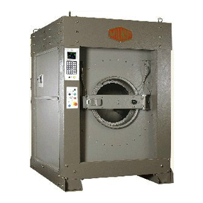
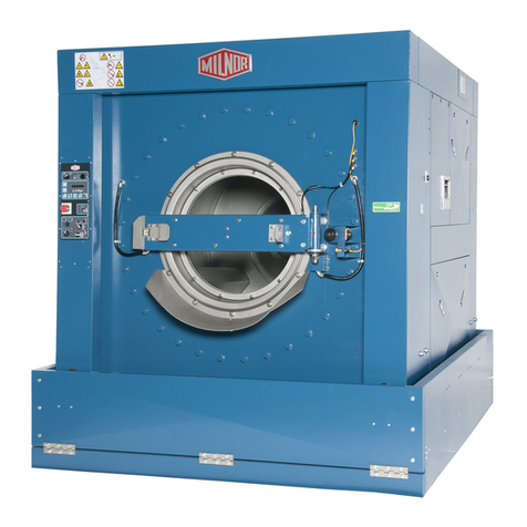
  9. Milnor C Series User manual

Milnor C Series User manual

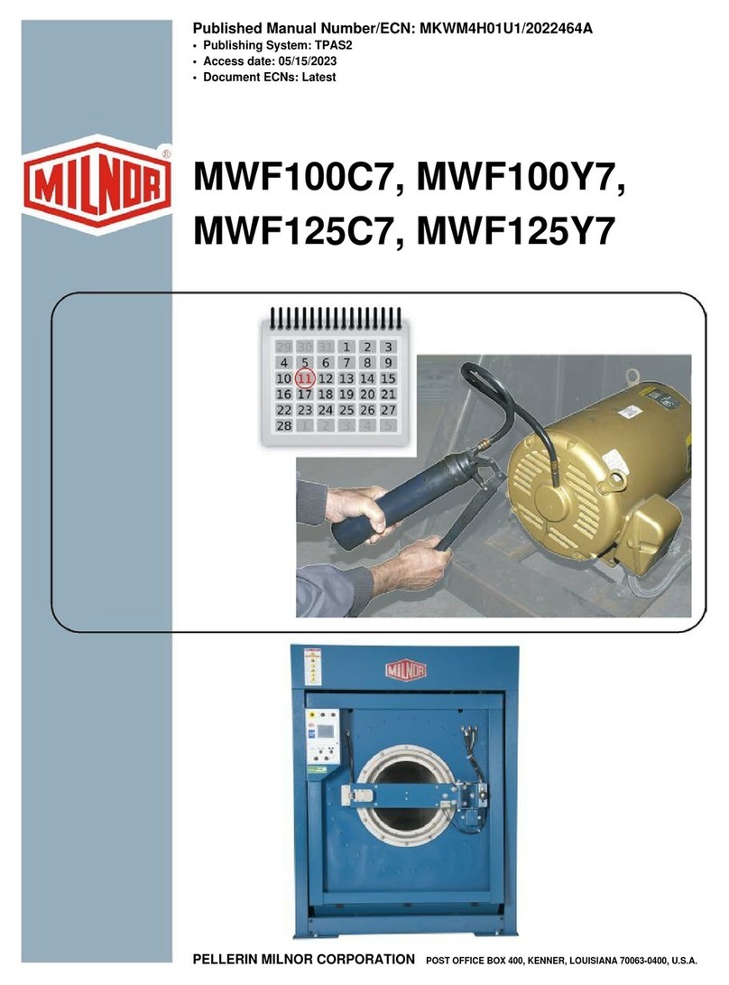
Published Manual Number/ECN: MAI30VXXAE/2002044N
• Publishing System: TPAS
• Access date: 01/30/2002
• Document ECN's: Latest Available
Installation—
30015, 30022 Cxx, Vxx,Txx
Rigid Mount
Washer-Extractors
PELLERIN MILNOR CORPORATION POST OFFICE BOX 400, KENNER, LOUISIANA 70063-0400, U.S.A.
Please Read
About the Manual Identifying Information on the Cover
The front cover displays pertinent identifying information for this manual. Most important, are
the published manual number (part number) /ECN (date code). Generally, when a replacement
manual is furnished, it will have the same published manual number, but the latest available ECN.
This provides the user with the latest information applicable to his machine. Similarly all
documents comprising the manual will be the latest available as of the date the manual was
printed, even though older ECN dates for those documents may be listed in the table of
contents.
When communicating with the Milnor factory regarding this manual, please also provide the
other identifying information shown on the cover, including the publishing system, access date,
and whether the document ECN’s are the latest available or exact.
References to Yellow Troubleshooting Pages
This manual may contain references to “yellow pages.” Although the pages containing
troubleshooting procedures are no longer printed on yellow paper, troubleshooting instructions, if
any, will be contained in the easily located “Troubleshooting” chapter or section. See the table of
contents.
Trademarks of Pellerin Milnor Corporation
The following, some of which may be used in this manual, are trademarks of Pellerin Milnor
Corporation:
Ampsaver®Dye-Extractor®Gear Guardian®Milnet®Staph-Guard®
Autolint®Dyextractor®Hands-Off®Milnor®System 4®
Auto-Purge®E-P Express®Hydro-Cushion®Miltrac System 7®
Autovac E-P OneTouch®Mildata®Miltron Totaltrol®
CBW®E-P Plus®
Comments and Suggestions
Help us to improve this manual by sending your comments to:
Pellerin Milnor Corporation
Attn: Technical Publications
P. O. Box 400
Kenner, LA 70063-0400
Fax: (504) 469-1849
Table of Contents
for MAI30VXXAE/2002044N
30015, 30022 Cxx, Vxx,Txx Rigid Mount Washer-Extractors
Page Description Document/ECN
1 Warranty BMP720097/92732A
3 How to Order Parts BMP720097R/72332A
4 Rigid Mount Washer-Extractor Installation & Service Safety MSIN0704AE/9271BV
7 About the Forces Transmitted by Milnor Washer-Extractors BIWUUI02/20001108
9 Glossary of Tag Illustrations - M-Style, 30" T-
Style, & 30" V-Style Washer-Extractors MSIUUMTGAE/2001134V
13 Section 1: Installation
14 Handling and Setting Procedures for Rigid Mount
30015 & 30022 Washer-Extractors MSIN0703BE/2001036V
18 Service Connections BIRQVI01/20020125
23 Section 2: Dimensional Drawings
25 Dimensional Drawing - 30015C4A & 30015C4T BD3015C4BE/2001332D
27 Dimensional Drawing - 30015V7J, T5E & T5X BD3015V7BE/2002044D
29 Dimensional Drawing - 30015J4P BD3015J4AE/2001064D
30 Dimensional Drawing - 30015J4P Options BD3015J4AB/2001064D
31 Dimensional Drawing - 30022C4A & C4T BD3022C4BE/2001332D
33 Dimensional Drawing - 30022V6J, T5E & T5X BD3022V6BE/2002044D
34 Dimensional Drawing - 30022V6J, T5E, & T5X Options BD3022V6BB/2001234D
35 Dimensional Drawing - Pedestal Base 30015
& 30022 Vxx, Txx BD30VBASAE/2000455D
3(//(5,10,/125&25325$7,21
/,0,7('67$1'$5':$55$17<
We warrant to the original purchaser that MILNOR machines including electronic
hardware/software (hereafter referred to as “equipment”), will be free from defects in material
and workmanship for a period of one year from the date of shipment from our factory with no
operating hour limitation. This warranty is contingent upon the equipment being installed,
operated and serviced as specified in the operating manual supplied with the equipment, and
operated under normal conditions by competent operators.
Providing we receive written notification of a warranted defect within 30 days of its discovery,
we will – at our option – repair or replace the defective part or parts, FOB our factory. We
retain the right to require inspection of the parts claimed defective in our factory prior to
repairing or replacing same. We will not be responsible, or in any way liable, for unauthorized
repairs or service to our equipment, and this warranty shall be void if the equipment is repaired
or altered in any way without MILNOR’s written consent.
Parts which require routine replacement due to normal wear – such as gaskets, contact points,
brake and clutch linings and similar parts – are not covered by this warranty, nor are parts
damaged by exposure to weather or to chemicals.
We reserve the right to make changes in the design and/or construction of our equipment
(including purchased components) without obligation to change any equipment previously
supplied.
ANY SALE OR FURNISHING OF ANY EQUIPMENT BY MILNOR IS MADE ONLY UPON
THE EXPRESS UNDERSTANDING THAT MILNOR MAKES NO EXPRESSED OR IMPLIED
WARRANTIES OF MERCHANTABILITY OR FITNESS FOR ANY PARTICULAR USE OR
PURPOSE. MILNOR WILL NOT BE RESPONSIBLE FOR ANY COSTS OR DAMAGES
ACTUALLY INCURRED OR REQUIRED AS A RESULT OF: THE FAILURE OF ANY OTHER
PERSON OR ENTITY TO PERFORM ITS RESPONSIBILITIES, FIRE OR OTHER HAZARD,
ACCIDENT, IMPROPER STORAGE, MISUSE, NEGLECT, POWER OR ENVIRONMENTAL
CONTROL MALFUNCTIONS, DAMAGE FROM LIQUIDS, OR ANY OTHER CAUSE BEYOND
THE NORMAL RANGE OF USE. REGARDLESS OF HOW CAUSED, IN NO EVENT SHALL
MILNOR BE LIABLE FOR SPECIAL, INDIRECT, PUNITIVE, LIQUIDATED, OR
CONSEQUENTIAL COSTS OR DAMAGES, OR ANY COSTS OR DAMAGES WHATSOEVER
WHICH EXCEED THE PRICE PAID TO MILNOR FOR THE EQUIPMENT IT SELLS OR
FURNISHES.
WE NEITHER ASSUME, NOR AUTHORIZE ANY EMPLOYEE OR OTHER PERSON TO
ASSUME FOR US, ANY OTHER RESPONSIBILITY AND/OR LIABILITY IN CONNECTION
WITH THE SALE OR FURNISHING OF OUR EQUIPMENT TO ANY BUYER.
BMP720097
92732A
1
2
How to order repair parts
Repair parts may be ordered either from the authorized dealer who sold you this
machine, or directly from the MILNOR factory. In most cases, your dealer will
have these parts in stock.
When ordering parts, please be sure to give us the following information:
1. Model and serial number of the machine for which the parts are required
2. Part number
3. Name of the part
4. Quantity needed
5. Method of shipment desired
6. In correspondence regarding motors or electrical controls, please include all
nameplate data, including wiring diagram number and the make or
manufacturer of the motor or controls.
All parts will be shipped C.O.D. transportation charges collect only.
Please read this manual
It is strongly recommended that you read the installation and operating manual
before attempting to install or operate your machine. We suggest that this manual
be kept in your business office so that it will not become lost.
PELLERIN MILNOR CORPORATION
32%2;.(11(5/$86$
FAX: Administration 504/468-9307, Engineering 504/469-1849, Service 504/469-9777
BMP720097R
72332A
3
MSIN0704AE/9271BV
ÈRIGID MOUNT WASHER-EXTRACTOR
INSTALLATION AND SERVICE SAFETY
ÊHazards During Assembly
ELECTROCUTION HAZARD—Contact with high voltage can kill or seriously in-
jure you.
☞All electrical connections must be made by a competent electrician.
ÊHazards During Servicing and Maintenance
ELECTROCUTION HAZARD—High voltage is present inside electric boxes, mo-
tors and many other components. Power switches on machine control panels
disable only control circuit power in certain boxes. You can be killed or seri-
ously injured on contact with high voltage.
☞Lock OFF and tag out power at the wall disconnect before servicing, except
where specifically instructed otherwise in this manual.
ENTANGLE AND CRUSH HAZARD—Belts and pulleys can entangle and crush
body parts.
☞Lock OFF and tag out power at the wall disconnect before servicing, except
where specifically instructed otherwise in this manual.
☞Insure belt guards are in place during service procedures.
B
ÊGeneral Safety Requirements
(specific warnings, next page and throughout manual)
Incorrect installation, neglected preventive maintenance, abuse, and/or improper repairs or changes to the
machine can cause unsafe operation and personal injuries, such as multiple fractures, amputations, or death. The
owner or his selected representative (owner/user) is responsible for understanding and ensuring the proper operation
and maintenance of the machine. The owner/user must familiarize himself with the contents of all machine instruc-
tion manuals. The owner/user should direct any questions about these instructions to a Milnor®dealer or the Mil-
nor®Service department.
Most regulatory authorities (including OSHA in the USA) hold the owner/user ultimately responsible for
maintaining a safe working environment. Therefore, the owner/user must do the following:
•recognize all foreseeable safety hazards within his facility and take actions to protect his personnel,
equipment, and facility
•require that personnel are familiar with all functional and safety aspects of the machine
•ensure safety devices installed on the machine are in place and properly maintained
•ensure all machine parts and assemblies are properly maintained.
ËLaundry Facility—Provide a supporting floor that is strong and rigid enough to support--with a reasonable
safety factor and without undue or objectionable deflection--the weight of the fully loaded machine and the forces
transmitted by it during operation. (For washer-extractors, see “ABOUT THE FORCES TRANSMITTED BY MIL-
NOR®WASHER-EXTRACTORS.”) Provide sufficient clearance for machine movement. Provide any safety
guards, fences, restraints, devices, and verbal and/or posted restrictions necessary to prevent personnel, machines,
or other moving machinery from accessing the machine or its path. Provide adequate ventilation to carry away heat
and vapors. Ensure service connections to installed machines meet local and national safety standards, especially
regarding the electrical disconnect (see the National Electric Code). Prominently post safety information, including
signs showing the source of electrical disconnect.
ËPersonnel—Inform personnel about hazard avoidance and the importance of care and common sense. Provide
personnel with the safety and operating instructions that apply to them. Verify that personnel use proper safety and
operating procedures. Verify that that personnel understand and abide by point-of-hazard tags on the machine and
procedure-specific precautions in the instruction manuals.
ËSafety Devices—Ensure that no one eliminates or disables any safety device on the machine or in ths facility.
Do not allow machine to be used with any missing guard or cover. Service any failing or malfunctioning device
before operating the machine.
ËMaintenance—Ensure the machine is inspected and serviced in accordance with the norms of good practice and
with the preventive maintenance schedule. Replace belts, pulleys, brake shoes/disks, clutch plates/tires, rollers,
seals, alignment guides, etc. before they are severely worn. Immediately investigate any evidence of impending
failure and make needed repairs (e.g., cylinder, shell, or frame cracks; drive components such as motors, gear boxes,
4
MSIN0704AE/9271BV (1 of 2)
ÈRIGID MOUNT WASHER-EXTRACTOR
INSTALLATION AND SERVICE SAFETY
ÊHazards During Assembly
ELECTROCUTION HAZARD—Contact with high voltage can kill or seriously in-
jure you.
☞All electrical connections must be made by a competent electrician.
ÊHazards During Servicing and Maintenance
ELECTROCUTION HAZARD—High voltage is present inside electric boxes, mo-
tors and many other components. Power switches on machine control panels
disable only control circuit power in certain boxes. You can be killed or seri-
ously injured on contact with high voltage.
☞Lock OFF and tag out power at the wall disconnect before servicing, except
where specifically instructed otherwise in this manual.
ENTANGLE AND CRUSH HAZARD—Belts and pulleys can entangle and crush
body parts.
☞Lock OFF and tag out power at the wall disconnect before servicing, except
where specifically instructed otherwise in this manual.
☞Insure belt guards are in place during service procedures.
B
ÊGeneral Safety Requirements
(specific warnings, next page and throughout manual)
Incorrect installation, neglected preventive maintenance, abuse, and/or improper repairs or changes to the
machine can cause unsafe operation and personal injuries, such as multiple fractures, amputations, or death. The
owner or his selected representative (owner/user) is responsible for understanding and ensuring the proper operation
and maintenance of the machine. The owner/user must familiarize himself with the contents of all machine instruc-
tion manuals. The owner/user should direct any questions about these instructions to a Milnor®dealer or the Mil-
nor®Service department.
Most regulatory authorities (including OSHA in the USA) hold the owner/user ultimately responsible for
maintaining a safe working environment. Therefore, the owner/user must do the following:
•recognize all foreseeable safety hazards within his facility and take actions to protect his personnel,
equipment, and facility
•require that personnel are familiar with all functional and safety aspects of the machine
•ensure safety devices installed on the machine are in place and properly maintained
•ensure all machine parts and assemblies are properly maintained.
ËLaundry Facility—Provide a supporting floor that is strong and rigid enough to support--with a reasonable
safety factor and without undue or objectionable deflection--the weight of the fully loaded machine and the forces
transmitted by it during operation. (For washer-extractors, see “ABOUT THE FORCES TRANSMITTED BY MIL-
NOR®WASHER-EXTRACTORS.”) Provide sufficient clearance for machine movement. Provide any safety
guards, fences, restraints, devices, and verbal and/or posted restrictions necessary to prevent personnel, machines,
or other moving machinery from accessing the machine or its path. Provide adequate ventilation to carry away heat
and vapors. Ensure service connections to installed machines meet local and national safety standards, especially
regarding the electrical disconnect (see the National Electric Code). Prominently post safety information, including
signs showing the source of electrical disconnect.
ËPersonnel—Inform personnel about hazard avoidance and the importance of care and common sense. Provide
personnel with the safety and operating instructions that apply to them. Verify that personnel use proper safety and
operating procedures. Verify that that personnel understand and abide by point-of-hazard tags on the machine and
procedure-specific precautions in the instruction manuals.
ËSafety Devices—Ensure that no one eliminates or disables any safety device on the machine or in ths facility.
Do not allow machine to be used with any missing guard or cover. Service any failing or malfunctioning device
before operating the machine.
ËMaintenance—Ensure the machine is inspected and serviced in accordance with the norms of good practice and
with the preventive maintenance schedule. Replace belts, pulleys, brake shoes/disks, clutch plates/tires, rollers,
seals, alignment guides, etc. before they are severely worn. Immediately investigate any evidence of impending
failure and make needed repairs (e.g., cylinder, shell, or frame cracks; drive components such as motors, gear boxes,
5
ÊHazards Requiring Immediate Service
MULTIPLE HAZARDS—Failure to maintain machine in proper working order can result in
fatal or serious injury to operators and/or damage to property. DO NOT permit operation
under any of the following circumstances:
☞Malfunctioning door interlock mechanism.
☞Malfunctioning limit switches.
☞Malfunctioning two hand inching.
☞Any evidence of cylinder damage.
☞Missing or removed guards, covers, or side panels.
☞Malfunctioning tilting components, including but not limited to safety limit switches,
electrical interlocks, and operator controls.
☞If any of these conditions occur:
•The machine makes a sound like skidding automobile tires as it comes out of extract.
•The wash or drain clutch does not disengage or it reengages during extract.
•V-belts jump off at the start of, during, or at the end of extract.
•A strange whining sound occurs at any time during extract.
B
6
About the Forces Transmitted by Milnor®Washer-extractors
Document..................... BIWUUI0
2
S
p
ecified Date................. 2000110
8
As-of Date.......................2000110
8
Access Date.....................2000110
8
About the Forces Transmitted by Milnor®
Washer-extractors
A
pp
licabilit
y
...........................WU
U
During washing and extracting, all washer-extractors transmit both static and dynamic
(cyclic) forces to the floor, foundation, or any other supporting structure. During washing, the
impact of the goods as they drop imparts forces which are quite difficult to quantify. Size for size,
both rigid and flexibly-mounted machines transmit approximately the same forces during
washing. During extracting, rigid machines transmit forces up to 30 times greater than equivalent
flexibly-mounted models. The actual magnitude of these forces vary according to several factors:
• machine size,
• final extraction speed,
• amount, condition, and type of goods being processed,
• the liquor level and chemical conditions in the bath preceding extraction, and
• other miscellaneous factors.
Estimates of the maximum force normally encountered are available for each Milnor®model
and size upon request. Floor or foundation sizes shown on any Milnor®document are only for
on-grade situations based only on previous experience without implying any warranty, obligation,
or responsibility on our part.
1. Rigid Machines
Size for size, rigid washer-extractors naturally require a stronger, more rigid floor,
foundation, or other supporting structure than flexibly-mounted models. If the supporting soil
under the slab is itself strong and rigid enough and has not subsided to leave the floor slab
suspended without support, on grade installations can often be made directly to an existing floor
slab if it has enough strength and rigidity to safely withstand our published forces without
transmitting undue vibration. If the subsoil has subsided, or if the floor slab itself has insufficient
strength and rigidity, a deeper foundation, poured as to become monolithic with the floor slab,
may be required. Support pilings may even be required if the subsoil itself is “springy” (i.e., if its
resonant frequency is near the operating speed of the machine). Above-grade installations of rigid
machines also require a sufficiently strong and rigid floor or other supporting structure as
described below.
2. Flexibly-mounted Machines
Size for size, flexibly-mounted machines generally do not require as strong a floor,
foundation, or other supporting structure as do rigid machines. However, a floor or other
supporting structure having sufficient strength and rigidity, as described in section 3, is
nonetheless vitally important for these models as well.
3. How Strong and Rigid?
Many building codes in the U.S.A. specify that laundry floors must have a minimum live
load capacity of 150 pounds per square foot (732 kilograms per square meter). However, even
compliance with this or any other standard does not necessarily guarantee sufficient rigidity. In
any event, it is the sole responsibility of the owner/user to assure that the floor and/or any other
supporting structure exceeds not only all applicable building codes, but also that the floor and/or
any other supporting structure for each washer-extractor or group of washer-extractors actually
7
has sufficient strength and rigidity, plus a reasonable factor of safety for both, to support the
weight of all the fully loaded machine(s) including the weight of the water and goods, and
including the published 360º rotating sinusoidal RMS forces that are transmitted by the
machine(s). Moreover, the floor, foundation, or other supporting structure must have sufficient
rigidity (i.e., a natural or resonant frequency many times greater than the machine speed with a
reasonable factor of safety); otherwise, the mentioned 360º rotating sinusoidal RMS forces can be
multiplied and magnified many times. It is especially important to consider all potential vibration
problems that might occur due to all possible combinations of forcing frequencies (rotating
speeds) of the machine(s) compared to the natural frequencies of the floor and/or any other
supporting structure(s). A qualified soil and/or structural engineer must be engaged for this
purpose.
Figure 1: How Rotating Forces Act on the Foundation
Typical Machine
Legend
A. Direction of force
B. Load
C. Rotation (Frequency = RPM / 60)
Figure 1 above is intended to depict both on-grade and above-grade installations and is
equally applicable to flexibly-mounted washer-extractors, as well as to rigid models installed
either directly on a floor slab or on a foundation poured integrally with the slab. Current machine
data is available from Milnor®upon request. All data is subject to change without notice and may
have changed since last printed. It is the sole responsibility of every potential owner to obtain
written confirmation that any data furnished by Milnor®applies for the model(s) and serial
number(s) of the specific machines.
— End of BIWUUI02 —
8
<B8DD<C604! "#E
7\_ccQbi_VDQW9\\ecdbQdY_^c±
=Cdi\U# DCdi\U# FCdi\U
GQcXUb5hdbQ d_bc
Illustration Explanation
Stop! Read the manual first for complete
instructions before continuing.
Do not jack the machine here.
Do not lift the machine here.
Use three point or four point lifting as
determined by the lifting eyes furnished. Rig
the load using lifting cables of sufficient size
and length to ensure cables are not
over-stressed.
Donotliftthemachine from one corner orone
side edge.
9
Illustration Explanation
Do not start this machine until the packing
materials, lifting brackets, etc. with this tag
attached or behind this panel are removed.
These materials are painted red. Safety stands
orbrackets(alsopaintedred)maybe provided
with this machine. Do not discard safety
stands or brackets
This motor or pump should rotate in the
direction of the arrow.
Do not start this machine until the part with
this tag is installed on the machine.
Do not remove this component from the
machine.
10
Illustration Explanation
Install the appropriate part here before
operating the machine.
During drain and extract, the cylinder must
rotate counterclockwise when viewed from
here.
Make cold water connection here.
Make hot water connection here.
H0
2
H0
2
7\_ccQbi _V DQ
W
9\\ecdbQdY_^c±
=Cdi\U #  DCdi\U  #  FCdi\U GQcXUb5hdbQSd_bc
11
Illustration Explanation
Make third (reuse) water connection here.
Make flushing water connection here.
Do not strike shell front of washer-extractors
during fork lifting. Striking shell front will
cause door to leak.
H0
2
H0
2
=C9EE=D715" !!#$F "  "
12
Section 1
Installation
13
MSIN0703BE/2001036V
ÈHANDLING AND SETTING PROCEDURES FOR
RIGID MOUNT 30015 & 30022 WASHER-EXTRACTORS
ÊHandling Precautions
1. Remove the protective coverings (leaving the machine on shipping skids) and carefully examine for possible
shipping damage. If the machine is damaged, notify the transportation company immediately.
NOTE: Once the machine is given to the carrier for delivery, it is the sole responsibility of the carrier to
ensure that no damage occurs during transit. In addition to readily apparent damage, carriers are liable for
concealed damage. Do not hesitate to file a claim with the carrier if the machine isdamaged in any way
during shipment. Milnor®will be glad to assist you in filing your claim, but is not responsible for any
shipping damage to the machine once it has been delivered to the carrier in good condition.
2. Consult Milnor®for instructions if crane lifting is required.
3. Use skids with the forklift. If possible, leave the machine on the shipping skids until it is about to be placed
in its final position. Once the skids are removed, take care in placing forks under the machine. Do not allow
the forks to come in contact with valves, piping, motors, etc., located under the machine.
4. Never push, pull, or exert pressure on any components that protrude from the machine frame (shell front,
door, supply injector, electric boxes, controls, belt guard, conduits, inlet piping, etc.).
5. Ensure that the shell door is closed and secured.
ÊSite Requirements
ËSpace Requirements
1. All openings and corridors through which equipment must pass during installation must be large enough to
accommodate the width and the height of the machine (as shown on the dimensional drawings). It is occa-
sionally possible to reduce the overall dimensions by removing piping or other special modifications. Con-
sult Milnor®for additional information.
2. Sufficient clearance must be provided for normal operation and maintenance procedures.
ËOperational Requirements
1. Allow sufficient ventilation for heat and vapors of normal operation to dissipate.
2. Provide easy access to controls. Operators must be able to reach and view all status lights, machine controls,
and any additional controls associated with the machine (e.g., electrical power connections, water and steam
shut-offs, etc.).
ËFoundation Requirements—The machine must be anchored in accordance with the installation instruc-
tions. The floor and/or all other support components must have sufficient strength (and rigidity with due considera-
tion for the natural or resonant frequency thereof) to withstand the fully loaded weight of the machine, including the
wet goods and any repeated sinusoidal (rotating) forces generated during its operation. Determining the suitability
of floors, foundations, and other supporting structures normally requires analysis by a qualified structural engineer.
See “ABOUT THE FORCES TRANSMITTED BY MILNOR® WASHER-EXTRACTORS” (See Table of Con-
tents) for more information.
ÊAnchoring Requirements
Machines must be securely anchored to an adequate foundation. Anchor bolt locations and foundation speci-
fications are provided on the dimensional drawing (see Table of Contents). However, never install anchor bolts
firmly in the foundation using only the dimensional drawing or a template. Approximate anchor bolt locations
may be determined from a foundation template (standard equipment on some machines, optional on others). Rec-
ommended anchor bolt installation (see dimensional drawing) calls for each anchor bolt to be set in a pipe sleeve.
The foundation template or dimensionaldrawing will only locate foundation boltsaccurately enough so that the play
of the bolt within the pipe sleeve permits the machine to fit anchor bolts. If another bolt installation procedure is
used, do not install the bolts until the machine is on site and bolt locations can be determined. Consult Milnor®
if any obstruction prevents the installation of any anchor bolt. Anchor bolts cannot be indiscriminately omitted.
STRIKE AND MACHINE DAMAGE HAZARDS—A machine can “rip” away from
position on foundation if the machine is not anchored and grouted in strict ac-
cordance with the dimensional drawing and setting instructions provided in
this manual. Damage resulting from improper installation is not covered by
warranty.
☞Strictly follow setting instructions and dimensional drawing guidelines when anchoring
and setting this machine.
☞Properly install anchor bolts at ALL anchor bolt holes on the machine.
14
MSIN0703BE/2001036V (1 of 2)
ÈHANDLING AND SETTING PROCEDURES FOR
RIGID MOUNT 30015 & 30022 WASHER-EXTRACTORS
ÊHandling Precautions
1. Remove the protective coverings (leaving the machine on shipping skids) and carefully examine for possible
shipping damage. If the machine is damaged, notify the transportation company immediately.
NOTE: Once the machine is given to the carrier for delivery, it is the sole responsibility of the carrier to
ensure that no damage occurs during transit. In addition to readily apparent damage, carriers are liable for
concealed damage. Do not hesitate to file a claim with the carrier if the machine isdamaged in any way
during shipment. Milnor®will be glad to assist you in filing your claim, but is not responsible for any
shipping damage to the machine once it has been delivered to the carrier in good condition.
2. Consult Milnor®for instructions if crane lifting is required.
3. Use skids with the forklift. If possible, leave the machine on the shipping skids until it is about to be placed
in its final position. Once the skids are removed, take care in placing forks under the machine. Do not allow
the forks to come in contact with valves, piping, motors, etc., located under the machine.
4. Never push, pull, or exert pressure on any components that protrude from the machine frame (shell front,
door, supply injector, electric boxes, controls, belt guard, conduits, inlet piping, etc.).
5. Ensure that the shell door is closed and secured.
ÊSite Requirements
ËSpace Requirements
1. All openings and corridors through which equipment must pass during installation must be large enough to
accommodate the width and the height of the machine (as shown on the dimensional drawings). It is occa-
sionally possible to reduce the overall dimensions by removing piping or other special modifications. Con-
sult Milnor®for additional information.
2. Sufficient clearance must be provided for normal operation and maintenance procedures.
ËOperational Requirements
1. Allow sufficient ventilation for heat and vapors of normal operation to dissipate.
2. Provide easy access to controls. Operators must be able to reach and view all status lights, machine controls,
and any additional controls associated with the machine (e.g., electrical power connections, water and steam
shut-offs, etc.).
ËFoundation Requirements—The machine must be anchored in accordance with the installation instruc-
tions. The floor and/or all other support components must have sufficient strength (and rigidity with due considera-
tion for the natural or resonant frequency thereof) to withstand the fully loaded weight of the machine, including the
wet goods and any repeated sinusoidal (rotating) forces generated during its operation. Determining the suitability
of floors, foundations, and other supporting structures normally requires analysis by a qualified structural engineer.
See “ABOUT THE FORCES TRANSMITTED BY MILNOR® WASHER-EXTRACTORS” (See Table of Con-
tents) for more information.
ÊAnchoring Requirements
Machines must be securely anchored to an adequate foundation. Anchor bolt locations and foundation speci-
fications are provided on the dimensional drawing (see Table of Contents). However, never install anchor bolts
firmly in the foundation using only the dimensional drawing or a template. Approximate anchor bolt locations
may be determined from a foundation template (standard equipment on some machines, optional on others). Rec-
ommended anchor bolt installation (see dimensional drawing) calls for each anchor bolt to be set in a pipe sleeve.
The foundation template or dimensionaldrawing will only locate foundation boltsaccurately enough so that the play
of the bolt within the pipe sleeve permits the machine to fit anchor bolts. If another bolt installation procedure is
used, do not install the bolts until the machine is on site and bolt locations can be determined. Consult Milnor®
if any obstruction prevents the installation of any anchor bolt. Anchor bolts cannot be indiscriminately omitted.
STRIKE AND MACHINE DAMAGE HAZARDS—A machine can “rip” away from
position on foundation if the machine is not anchored and grouted in strict ac-
cordance with the dimensional drawing and setting instructions provided in
this manual. Damage resulting from improper installation is not covered by
warranty.
☞Strictly follow setting instructions and dimensional drawing guidelines when anchoring
and setting this machine.
☞Properly install anchor bolts at ALL anchor bolt holes on the machine.
15
ÊSetting Procedures
See FIGURE 1 during the following procedures:
1. With the machine near the final location, unbolt the shipping
skids. Observing all precautions, lift the machine off its
skids and lower the machine onto temporary blockings as
shown in FIGURE 1. Install anchor bolts, taking care to
align the bolts with the base plates to avoid bolt thread
damage.
2. Determine that the minimum clearance between each
base plate and floor surface is as specified (see dimen-
sional drawings). Shim the machine at temporary block-
ings to level the machine from left to right and front to
back. Use a carpenter’s level along the right and left side
of the base to determine if the machine is level from front
to back. Place a level laterally across the base plates to de-
termine if the machine is level from right to left.
NOTE: Do not pull on conduit when moving the machine.
Tampering with the conduit may require adjustment of the
door switch.
MACHINE DAMAGE AND MALFUNCTION HAZARDS—Tightening anchor bolt fasteners
onto spacers (without grout or with improperly applied grout) twists the machine frame and
causes cylinder misalignment.
☞Never tighten anchor bolt fasteners before grouting.
☞Grout must displace total clearance between base plate and existing foundation floor.
Voids must not exist!
3. After determining the final position of the machine, apply grout between the existing foundation floor and
base plates, while observing the following considerations:
•All machines are designed to be grouted under the full area of all base plates. Grout prevents the anchor
bolts from distorting the frame when the fasteners are tightened. Total area under each base plate must be
completely filled with grout (see dimensional drawings). Voids under base plates can magnify vibration,
causing unsatisfactory operation. Use only industrial strength non-shrinking grout.
•If the grout (after mixing) is of proper consistency, pack or trowel it by hand.
•If the grout (after mixing) is too thin (causing it to flow from under the base pads), install temporary
cardboard framing around the pads to retain the grout until it cures.
4. After the grout has completely cured, raise the machine sufficiently to remove all temporary blocking and
shims. Be careful to avoid disturbing or damaging grout.
5. Tighten all foundation fasteners until they contact the top of the base plate. Center bolt holes are located in-
side rear console. Install center hold down bolts properly to ensure successful operation.
6. Tighten all fasteners evenly, using only one-quarter turn on each fastener before moving to the next one.
While tightening, frequently skip from front to back and right to left to insure uniform tension. After tighten-
ing all fasteners, check each fastener at least twice.
ÎFIGURE 1(MSIN0703BE)
ÎTemporary Blocking Points
for 30015 and 30022
Cxx, Sxx, Mxx, Txx and
Vxx Machines
16

This manual suits for next models

4

Other Milnor Washer manuals

Milnor 36021C4E User manual

Milnor

Milnor 36021C4E User manual

Milnor Mark II User manual

Milnor

Milnor Mark II User manual

Milnor MWF63J7 Manual

Milnor

Milnor MWF63J7 Manual

Milnor MilTouch MWF36Z8 Manual

Milnor

Milnor MilTouch MWF36Z8 Manual

Milnor 76032 User manual

Milnor

Milnor 76032 User manual

Milnor 76028 G3 CBW Manual

Milnor

Milnor 76028 G3 CBW Manual

Milnor 48032BTL Installation and operating manual

Milnor

Milnor 48032BTL Installation and operating manual

Milnor MWF100C7 User manual

Milnor

Milnor MWF100C7 User manual

Milnor 30022X8W User manual

Milnor

Milnor 30022X8W User manual

Milnor 30022V8Z Manual

Milnor

Milnor 30022V8Z Manual

Milnor 30 Series User manual

Milnor

Milnor 30 Series User manual

Milnor 30015V7J User manual

Milnor

Milnor 30015V7J User manual

Milnor 30015T6X Quick start guide

Milnor

Milnor 30015T6X Quick start guide

Milnor 30 Series Operating manual

Milnor

Milnor 30 Series Operating manual

Milnor 30022H7J Installation and operating manual

Milnor

Milnor 30022H7J Installation and operating manual

Milnor MWF27J8 Manual

Milnor

Milnor MWF27J8 Manual

Milnor 48040F7 Series Manual

Milnor

Milnor 48040F7 Series Manual

Milnor MWF63C Series Operating manual

Milnor

Milnor MWF63C Series Operating manual

Milnor 36021 Operating manual

Milnor

Milnor 36021 Operating manual

Milnor System 7 User manual

Milnor

Milnor System 7 User manual

Milnor Mark II Instruction Manual

Milnor

Milnor Mark II Instruction Manual

Milnor 42030V Series User manual

Milnor

Milnor 42030V Series User manual

Milnor 60044 SG3 User manual

Milnor

Milnor 60044 SG3 User manual

Milnor Staphguard 42026 QHP User manual

Milnor

Milnor Staphguard 42026 QHP User manual

Popular Washer manuals by other brands

Fisher & Paykel CLEANSMART WL8O60P installation guide

Fisher & Paykel

Fisher & Paykel CLEANSMART WL8O60P installation guide

Haws 7603 Installation, operation & maintenance instructions

Haws

Haws 7603 Installation, operation & maintenance instructions

Kenmore 41744152400 installation instructions

Kenmore

Kenmore 41744152400 installation instructions

Indesit IWC 61251 Instructions for use

Indesit

Indesit IWC 61251 Instructions for use

Miele PWM 916 SD Installations plan

Miele

Miele PWM 916 SD Installations plan

Indesit IWD 71482 Instructions for use

Indesit

Indesit IWD 71482 Instructions for use

Whirlpool LA6700XK Use & care guide

Whirlpool

Whirlpool LA6700XK Use & care guide

Beko WMB 71241 PTLC manual

Beko

Beko WMB 71241 PTLC manual

Whirlpool WFW9500TC - Duet Steam - 27in Front-Load... Use and care guide

Whirlpool

Whirlpool WFW9500TC - Duet Steam - 27in Front-Load... Use and care guide

Whirlpool 8524742 installation instructions

Whirlpool

Whirlpool 8524742 installation instructions

Amana RS3100007 Service manual

Amana

Amana RS3100007 Service manual

Miele W 916 operating instructions

Miele

Miele W 916 operating instructions

Haier HWM120-0523S user manual

Haier

Haier HWM120-0523S user manual

Samsung WT80S0(P) Owner's instructions

Samsung

Samsung WT80S0(P) Owner's instructions

Bosch WGG1420LSN User manual and installation instructions

Bosch

Bosch WGG1420LSN User manual and installation instructions

Beko WTV 7732 XW1 user manual

Beko

Beko WTV 7732 XW1 user manual

Electrolux EWF 1230 operating instructions

Electrolux

Electrolux EWF 1230 operating instructions

LG FM1207N6W owner's manual

LG

LG FM1207N6W owner's manual

manuals.online logo
manuals.online logoBrands
  • About & Mission
  • Contact us
  • Privacy Policy
  • Terms and Conditions

Copyright 2025 Manuals.Online. All Rights Reserved.