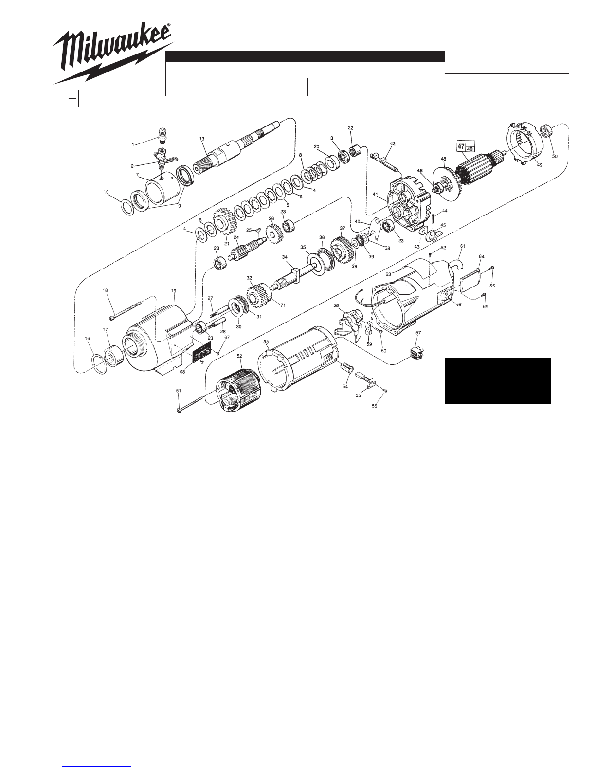
FIG. PART NO. DESCRIPTION OF PART NO. REQ.
48 22-84-0790 Fan (1)
49 42-14-0291 Baffle (1)
50 02-04-1041 Ball Bearing (1)
51 06-82-9152 10-24 x 2-3/4" Pan Hd. Sem. T-25 (2)
52 18-70-0290 Field (1)
53 23-16-1410 Motor Insulator (1)
54 22-20-0680 Brush Tube (2)
55 22-18-0702 Carbon Brush Assembly (2)
56 06-82-8835 8-32 x 5/16" Pan Hd. Sem.T-20 (2)
57 22-56-0470 Terminal Block (1)
58 22-38-0140 Wire Trap (1)
59 31-17-0200 Cord Clamp (1)
60 06-82-7326 8-16 x 1" Pan Hd. Plastite T-20 (2)
61 23-37-0200 Control Assy. (See Bull. 58-03-0021) (1)
62 06-72-1720 Service Rivet (2)
63 12-99-2145 Service Nameplate (1)
64 22-32-0350 Brush Cover (2)
65 06-82-5316 8-32 x 1/2" Pan Hd. Slt. Taptite T-20 (2)
66 28-50-6363 Motor Housing (1)
67 06-82-5266 4-40 x 1/4" Pan Hd. TaptiteT-10 (2)
68 12-98-3020 Instruction Plate (1)
69 06-95-5200 8-32 x 5/16" Slt. Hex Hd. Screw (1)
71 45-36-0225 Gear Spacer (1)
49-96-4700 1-3/8" Open End Wrench (1)
49-96-0050 3/32" Hex Socket Wrench (1)
49-96-0085 3/16" Hex Socket Wrench (1)
45-56-0210 Strap And Buckle (1)
61-10-0660 Retaining Nut Spanner Tool (1)
61-30-0061 Water Seal Jig (1)
MILWAUKEE ELECTRIC TOOL CORPORATION
13135 W. LISBON RD., BROOKFIELD, WI 53005
Drwg. 4
FOR MOUNTING DRILL MOTOR USE:
06-75-3090 1/4-20 x 7/8" Socket Hd. Screw (4)
06-97-4050 1/4" Split Ring Lock Washer (4)
FIG. LUBRICATION
19 18 Oz. Type "J" Grease, No. 49-08-4220.
FIG. PART NO. DESCRIPTION OF PART NO. REQ.
1 42-90-0210 Water Hose Fitting (1)
2 45-80-0060 Shut Off Valve (1)
3 06-57-1050 Retaining Nut (1)
4 45-88-1140 Thrust Washer (2)
5 43-06-0160 Clutch Disc-Outer (3)
6 43-06-0150 Clutch Disc-Inner (5)
7 43-76-0051 Water Swivel Hsg. w/ 06-83-2430 Scr. (1)
8 40-50-2150 Disc Spring (4)
9 45-06-0635 Seal (2)
10 45-88-8565 Washer (Bag of 2) (1)
13 38-50-6020 Spindle (1)
16 34-80-3800 Retaining Ring (1)
17 02-20-2515 Ball Bearing (1)
18 06-82-9202 1/4-20 x 4-1/4" Taptite T-30 (4)
19 28-14-1870 Gear Case Assy.(Inc. 06-65-1535 Pin) (1)
20 45-36-1520 Spindle Spacer (1)
21 32-75-3430 Spindle Gear (1)
22 02-50-4830 Needle Bearing (1)
23 02-04-1205 Ball Bearing (4)
24 36-66-3751 Pinion Shaft Assy. (1)
25 06-42-1600 Woodruff Key (1)
26 32-40-1581 Intermediate Gear (1)
27 40-50-6300 Shifting Spring (2)
28 44-70-0100 Shifting Plunger (2)
30 45-88-0520 Thrust Bearing Washer (1)
31 02-80-1800 Thrust Bearing (1)
32 32-10-0060 High Speed Gear (1)
34 36-14-0720 Clutch Pinion Shaft (1)
35 45-88-0530 Thrust Bearing Washer (1)
36 02-80-5000 Thrust Bearing (1)
37 32-10-0051 Clutch Gear Assembly (1)
38 45-88-0510 Thrust Bearing Washer (2)
39 02-80-1200 Thrust Bearing (1)
40 45-98-0090 Shifting Yoke (1)
41 14-13-0210 Diaphragm Assy.(Inc. 06-65-1155 Pin) (1)
42 30-15-0272 Shift Cam (1)
43 43-44-0580 Foam Gasket (2)
44 06-65-0840 1/8 x 3/4" Groove Pin (1)
45 25-60-0056 Shifting Knob (1)
46 02-04-1229 Ball Bearing (1)
47 16-70-0320 Armature (1)
WIRING INSTRUCTION
REVISED BULLETIN DATE
SPECIFY CATALOG NO. AND SERIAL NO. WHEN ORDERING PARTS
SERVICE PARTS LIST BULLETIN NO.
STARTING
SERIAL NO.
55-16-7001
CATALOG NO. 4004-55 841B
Mar. 2008
DYMODRILL with INTERNAL CLUTCH
0
00 EXAMPLE:
Component Parts (Small #)
Are Included When Ordering
The Assembly (Large #).
58-03-0021
55-16-7000
SEE THE REVERSE SIDE
FOR THE SERVICING
OF THE INTERNAL
CLUTCH MECHANISM


