Mimosa SIGNATURE 3171022 User manual

OUTDOOR GAS HEATER
-TABLETOP SILVER
Provides warmth and ambiance for outdoor settings
AGA Gas Certified
Important: Please retain these instructions for future use
3171022
3171022 JDSTT ODS

Gas connections on the heater are leak tested at the factory prior to shipment. A complete gas
tightness check must be performed due to possible mishandling in shipment or excessive pressure
being applied to the heater gas connections.
1. Make a soap solution of one part liquid detergent and one part water.
Make sure the control knob on the heater is off and the gas valve on the cylinder is off before
mixing the soapy solution.
2.Turn on the gas bottle.
3. Apply the soap solution to the gas connections using a soft bristle brush.
Soap bubbles will appear
if there is a gas leak.
In case of a leak, turn off
the gas supply. Tighen any
leaking fittings, then turn the
gas supply on and re-check.
If there is a leak anywhere
on the gas cylinder, do not
use the cylinder. Locate the
leaking cylinder outdoors
away from sources of
ignition, then contact your
local gas authority or
cylinder exchange provider
to arrange disposal.
Warning:
Do not operate the appliance until all gas leaks have been rectified.
Never leak test while smoking.
+++
+
+
+
Regulator / Cylinder
Hose / Regulator
Detergent
(Table)
Gas Leak Test

Table Of Contents
Warning Safety Rules...............................................................Page1
Safety Requirements Before Operation.................................Page2
Diagrammatical Representation Of ‘Outdoor Areas’...........Page3
Safety Rules For Outdoor Gas Appliance............................. Page4
Table Heater Stand And Location..........................................Page5
Gas Requirements...................................................................Page5
Procedure For Leakage Test...................................................Page6
Operation and Storage...........................................................Page7
Parts and Specification...........................................................Page8
Assembly Parts.........................................................................Page9
Assembly Procedure...............................................................Page10
Pilot Service ..............................................................................Page13
Problems Check List................................................................Page14
Product Warranty.....................................................................Page15
PLEASE READ THE FOLLOWING SAFETY RULES PRIOR
TO OPERATION OF THE HEATER
W
WA
AR
RN
NI
IN
NG
G
If you smell gas:
1. Shut off gas to the appliance.
2. Extinguish any open flame.
3. If odour continues test for leaks as detailed on page 8.
W
WA
AR
RN
NI
IN
NG
G
1. This patio heater is not for commercial use.
2. Do not store or use petrol or other flammable vapors and liquids in the vici nity of this or any other appliance.
3. An LP cylinder not connected for use should not be stored in the vicinity of this or any other appliance.
4. Do not place articles on or against this appliance.
5. Do not use or store flammable materials near this appliance.
6. The guard is fitted to this appliance to reduce risk or fire or injury from burns and no part of it should be removed.
7. Do not spray aerosols in the vicinity of this appliance while it is in operation.
8. Do not leave patio heater unattended during use
9. Children must be supervised by an adult during use
10. Do not use your patio heater within 1.5m of combustible materials
11. Do not handle or move the patio heater when in use of i
12. DO NOT INSTALL OR USE THIS APPLIANCE IND
14. DO NOT USE AN ADAPTOR AT THE CYLINDER CONNECTION
OORS
13. DO NOT MODIFY THIS APPLIANCE
f surface is hot.
W
WA
AR
RN
NI
IN
NG
G:
:
W
WA
AR
RN
NI
IN
NG
G:
:
For Outdoor Use Only
Improper installation, adjustment, alteration, service or maintenance can cause personal injury or
property damage. Read the installation, operating and maintenance instructions thoroughly before installing or servi
-cing this equipment.
WARNING
WARNING
Warning Safety Rules
Page 1

This appliance shall be installed in accordance with these installation instructions, local gas
fitting regulations, municipal building codes and AS/NZS 5601.1 - Gas Installations and any
other statutory regulations.
This outdoor gas appliance is not intended to be installed in or on recreational vehicles and/or
boats.
Maintain proper clearances from combustible construction the specific minimum clearances
from such construction to the sides and back of the outdoor gas appliance. (See page 5, Diagra
Inspect the hose before each use of the outdoor gas appliance.
If it is evident there is excessive abrasion or wear out, or the hose is cut, it must be replaced
prior to this outdoor gas appliance being put into operation. The replacement hose assembly
shall be that specified by the manufacturer.
Ensure gas hose is installed correctly, including positioning the hose out of pathways where
may trip over it or in areas where the hose may be subject to accidental damage.
Maintenance Instruction
Keep outdoor gas appliance area clear and free from combustible materials, petrol
and other flammable vapors and liquids.
Do not obstruct the flow of combustion and ventilation air.
Keep the ventilation opening(s) of the cylinder enclosure free and clear from debris.
Visually check burner flames.
Clean this outdoor gas appliance, including special surfaces, if necessary.
Check and clean burner tubes for insects and insect nests, A clogged tube can lead
to a fire beneath the burner head.
Maintain adequate clearance around air openings into the combustion chamber, clearances
from combustible material, provisions accessibility and for combustion and ventilating air
supply.
Certain
Remove all transit protection before operating this heater.
materials or items, whenstored under the appliance, willbe subjected to radiant heat
and could be seriously damaged.
-mmatical Representation of ‘OUTDOOR AREAS’ )
people
Safety Requirements Before Operation
Page 2
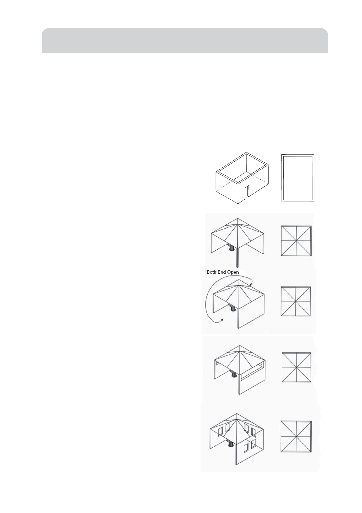
This appliance shall only be used in an above ground open-air situation with natural ventilation,
without stagnant areas, where gas leakage and products of combustion are rapidly dispersed by wind
and natural convection. Any enclosure in which the patio heater is used shall comply with one of the
following:
With walls on all sides, but at least one permanent opening at ground level and no overhead cover
(figure 1).
(figure1).
Within a partial enclosure that includes an
overhead cover and no more than two walls.
These walls may be parallel or at right angles
to each other. (figure 2 & 3)
(figure 2)
Within a partial enclosure that includes an
overhead cover and more than two walls,
(figure 3)
the following shall apply:
a). One wall that is equivalent to at least
25% of the total wall area is completely
open (figure 4)
(figure 4)
b). 30% or more in total of the remaining
wall area is open and unrestricted. (figure 5)
In the case of balconies, at least 20% of the total wall
)5erugif(.detcirtsernudnaneponiamerdnaebllahsaera
Diagrammatical Representation Of ‘Outdoor Areas’
Page 3

W
WA
AR
RN
NI
IN
NG
G:
:
1. Children and adults should be alerted to the hazards of high surface temperatures and should stay away to avoid burns or
clothing ignition.
2. Young children should be carefully supervised when they are in the area of the heater.
3. Clothing or other flammable materials should not be hung from the heater, or placed on or near the heater.
4. Any guard or other protective device removed for servicing, the appliance must be replaced prior to operating.
5. Service and repair shall be carried out only by authorised personnel. The heater should be inspected before use .
More frequent cleaning may be required as necessary. It is imperative that the control compartment, burners and circulating air
passageway of the appliance be kept clean.
6. THIS APPLIANCE SHOULD NOT BE INSTALLED OR USED INDOORS.
This outdoor gas appliance shall be used only outdoors and shall not be used in a building,
garage or any other enclosed area. If used indoors or in enclosed areas, personal injury or
property damage may occur.
When this outdoor gas appliance is not in use, the gas must be turned off at the supply cylinder.
Storage of this outdoor gas appliance indoors is permissible only if the cylinder is
disconnected and removed from the outdoor gas appliance.
Cylinders must be stored outdoors in a well-ventilated area out of the reach of children.
Disconnected cylinders must have threaded valve plugs tightly installed and must not be
stored in a building, garage or any other enclosed area.
The pressure regulator and hose assembly supplied with the outdoor gas appliance must be
used. Replacement pressure regulators and hose assemblies must be those specified by the
manufacturer.
The cylinder supply system must be arranged for vapor withdrawal.
The cylinder used must include a collar to protect the cylinder valve.
Safety Rules For Outdoor Gas Appliance
Page 4
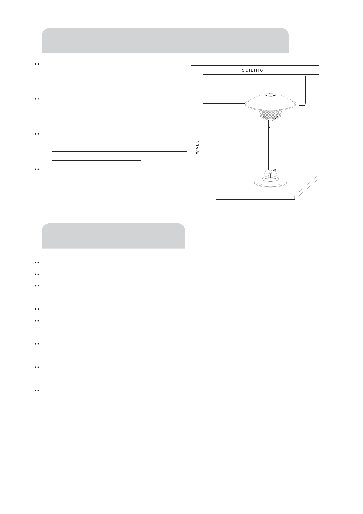
The garden table heater is for outdoor
use only . Always ensure that adequate
fresh air ventilation is provided.
Always maintain proper clearance to
combustible materials, i.e. top 46 cm and
sides 61 cm minimum.
Garden table heater must be fixed on a
stable and strong table with a minimum height
of 600mm from the floor level.
Never operate heater in an explosive
atmosphere like in areas where petrol or
other flammable liquids or vapors are
stored.
Use propane gas only.
Operating Pressure: 2.75kPa.
Consumption: 12.0MJ/h
Injector Size: 1.00mm
The pressure regulator and hose assembly to be used must conform to local standard codes.
The installation must conform to local codes, or in the absence of local codes, with the
standard for the storage and handling of liquid petroleum gases.
A dented, rusted or damaged propane tank may be hazardous and should be checked by your
tank supplier. Never use a propane tank with a damaged valve connection.
The propane tank must be arranged to provide for vapor withdrawal from the operating
cylinder.
Never connect an unregulated propane tank to the heater.
61 cm
46 cm
Table Heater Stand and Location
Gas Requirements
Page 5

NEVER CONNECT AN UNREGULATED GAS SUPPLY TO THIS APPLIANCE
PRECAUTIONS
Periodically check the whole gas system for leaks.
Immediately check for leaks if smell of gas is detected.
Extinguish all open flames during leakage test or when smell of gas is detected.
Never smoke while performing leak test.
If you cannot stop a leak, turn off the gas supply immediately and contact the dealer where
you bought your heater unit, or your gas supplier.
The appliance must be checked with a full gas tank.
DO NOT use the heater until you have performed leak test on all the connections and verified
that your unit does not leak.
Use only parts supplied with your Patio Heater. Substitution can void the warranty.
TESTING FOR LEAKAGE
Gas connections on the appliance are leak tested at the factory prior to shipment. Possible
mishandling of the appliance during the shipment might contribute to product integrity as a whole. A
complete gas leakage test must be performed again at the installation site. Please follow the
procedure below for leakage test.
Make a soap solution of one part liquid detergent and one part water. The soap solution can be
applied with spray bottle, brush or rag. Soap bubbles will appear where a leak is present.
Make sure the safety control valve is in the “OFF” position.
Turn ON the gas supply and check for bubbles from the hoses and connections. Presence of
bubbles means that a leak path is present.
If a leak is present, turn OFF the gas supply immediately, tighten any leaking fitting, turn gas
supply ON and recheck.
VISUALLY CHECKING BURNER FLAMES
The flame pattern at the emitter grid should be visually checked whenever the appliance is operated.
Under the following conditions the appliance should be turned off immediately and NOT operated
again until repairsare made:
When black soot accumulates on the emitter grid.
Procedure For Leakage Test
Page 6
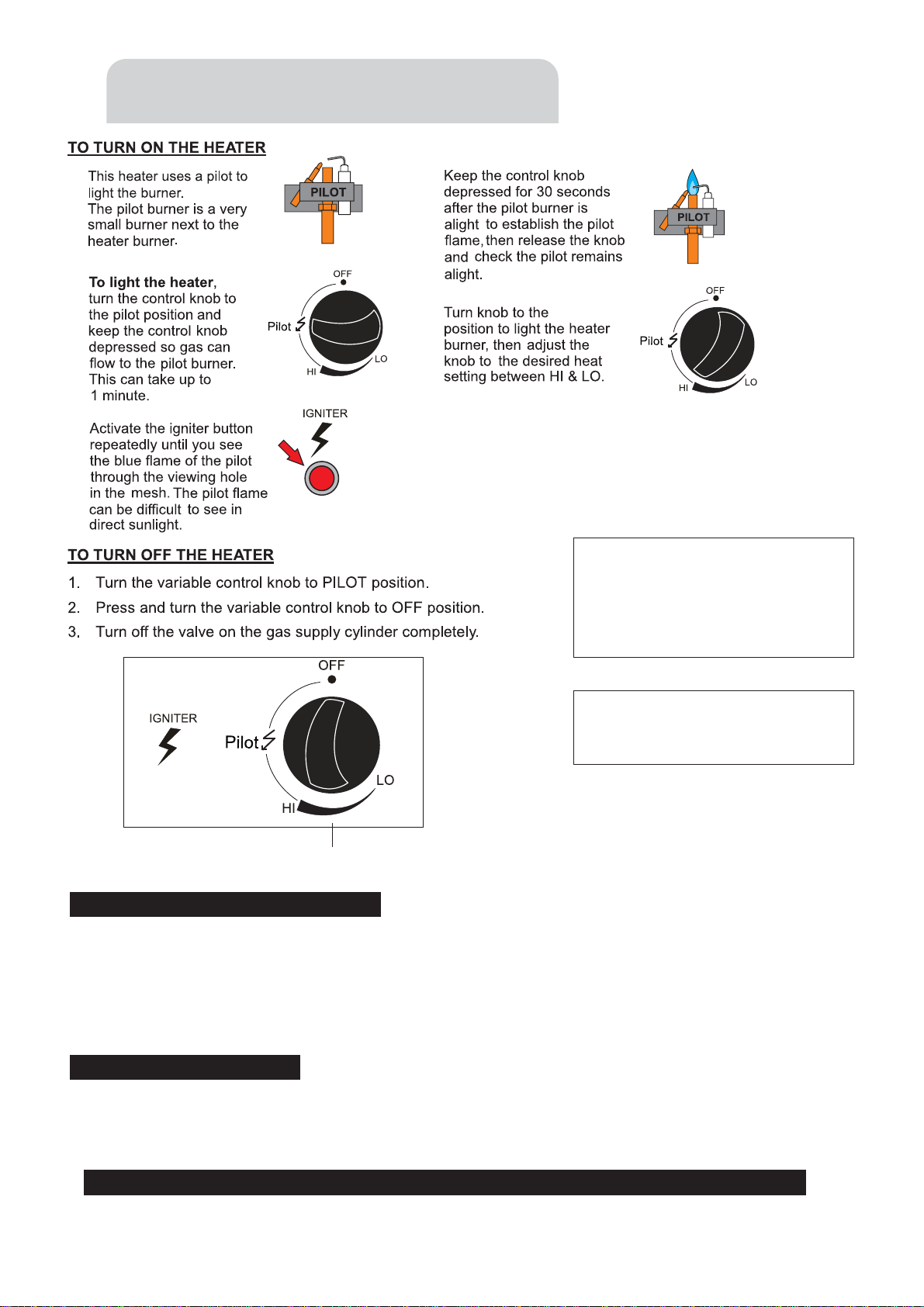
TO ST ORE THE HEATER UNIT
1. Turn the gas tank to complete closed position.
2. Disconnect the regulator from the gas cylinder valve.
3. Inspect the gas tank for damage. If you suspect that your tank is damaged, return it to your gas
tank supplier .
4. Store the gas tank in a well-ventilated area. Never store the gas tank below ground (for example, basement).
1. Wipe off tarnished surfaces with soft, moist rag.
2. Do not use harsh chemical or abrasives to clean the heater housing. If necessary , use mild
detergent.
CLEANING AND CARE
rpmIrPgnithgiLreporudecoes rPrOyrujnIlanosrePesuaCyaM operty Damage.
THE GUARD IS FITTED TO THIS
APPLIANCE TO REDUCE THE RISK
OF FIRE OR INJURY FROM BURNS
AND NO PART OF IT SHOULD BE
REMOVED.
WHEN LIGHTING HEATER, KEEP
FACE AWAY FROM EMITTER
GUARD.
1.
2.
3.
5.
4.
HI
Variable Control knob
Operation and Storage
Page 7

Flame screen guard
Main pole
Reflector
Control housing
Base
Rubber ring
Gas hose
Gas regulator
Safety chain
Parts and Specification
Page 8
A. Specification
For outdoor use only
Uses propane gas only
Operating Pressure: 2.75kPa
Consumption: 12.0MJ/h
Weight: 5kg
Height: 900 mm approx
B.Table of openings
Gas pressure (kPa) Main opening
2.75 1.0mm
Tools needed:
Adjustable opening wrench
Slip joint pliers
Philips screwdriver
Spray bottle of soap solution for leakage test
Other parts supplied:
stloBmm61×6Mscp4
3 pcs Reflector Supporting Bolts
9 pcs 6 mm washers
Smm8x4Mscp4 tainless Steel Screws
3 pcs M6 castle nuts
1 pc table mounting bracket
2 pcs Wing Nut
2 pcs Table Supporting Bolts
Reflector 535 x (D)100 mm
Flame screen guard
2pcs small washers for table bracket
Assembly Parts
Page 9

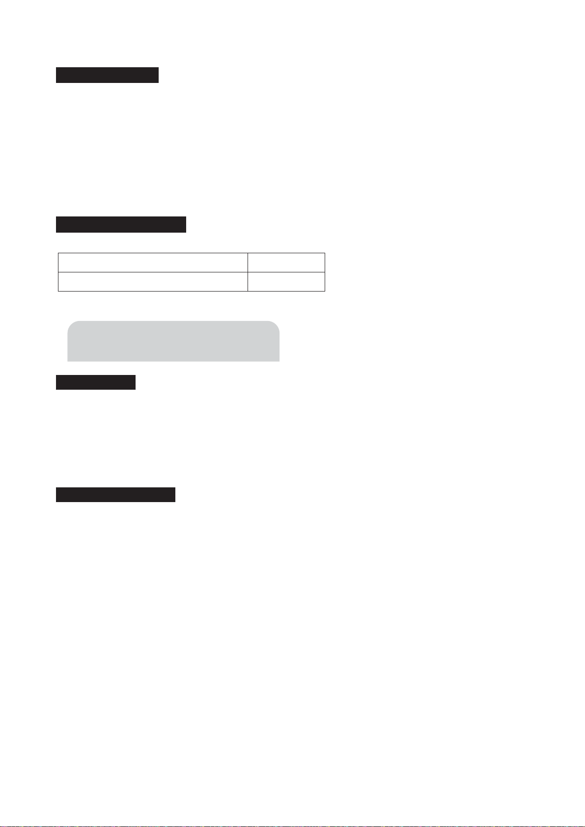
STEP 1:
1-1.
1-2.
1-3.
Put the base together with the main body.
Use 4 pcs M6×16 mm bolts to join the base and the
main body.
Tighten each of the bolts.
STEP 2: STEP 1
2-1.
2-2.
2-3.
2-4.
Join 3pcs supporting bolts & 3pcs washers to the
flame screen.
Put the flame screen into burner base.
Use 4 pcs M4×8 mm stainless steel screws to join
the flame screen and burner base as shown.
Tighten each of the screws.
STEP 2
STEP 3:
3-1. Place the flame screen guard cover over the burner
head, and align with holes around the burner base.
STEP 3
Main body
Base
Bolts
Flame screen
Supporting bolt
Washer
Screw
Flame Screen Guard
Hole
Assembly Procedure
Page 10
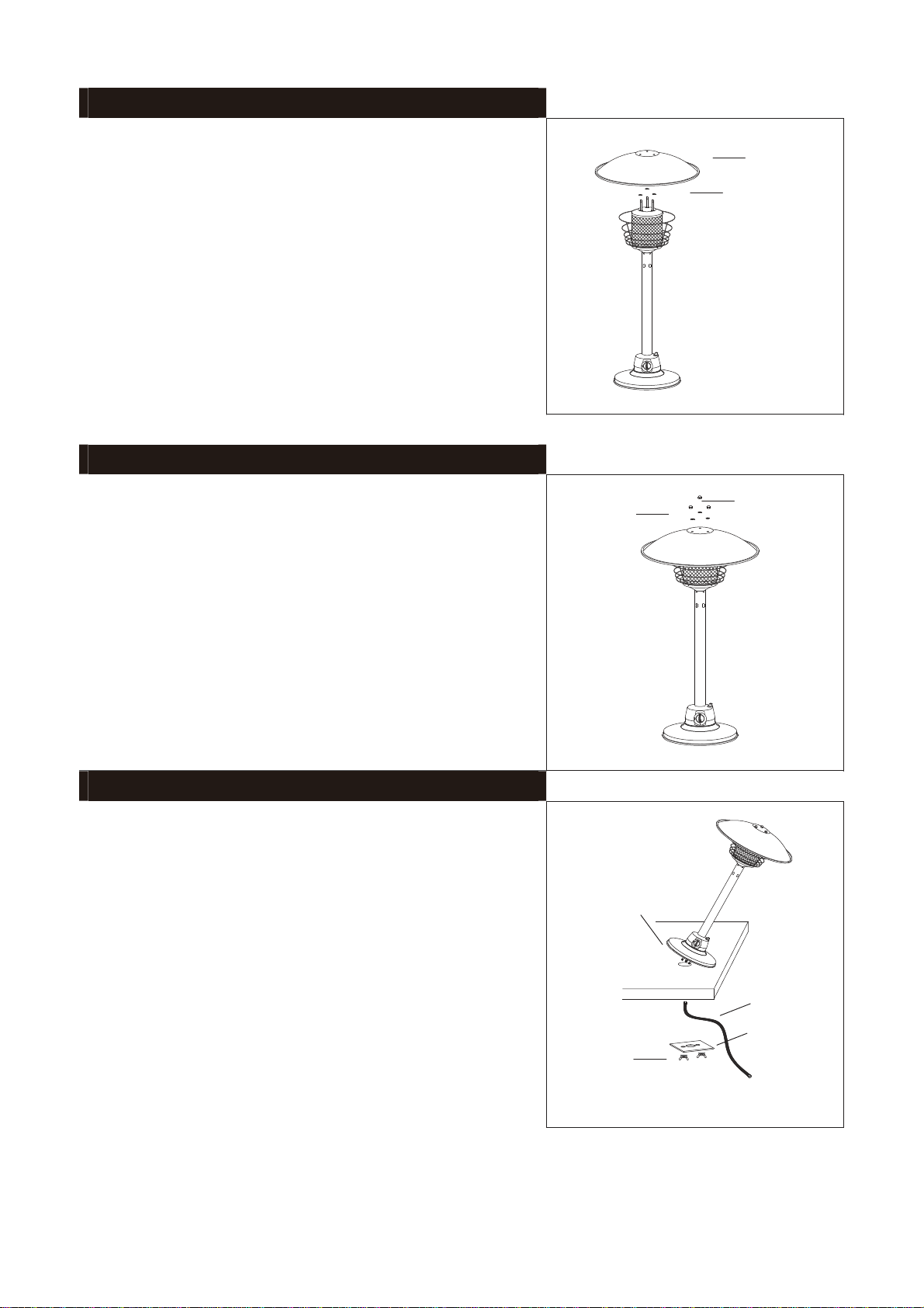
STEP 4:
4-1.
4-2.
Set 3 pcs washers above the 3 pcs supporting bolts.
Put reflector canopy onto the top of flame screen
aligning through the 3 pcs supporting bolts.
STEP 4
STEP 5:
5-1.
5-2.
Place 3 pcs washers & 3 pcs castle nuts on each
reflector supporting bolts.
Tighten each of the castle nuts.
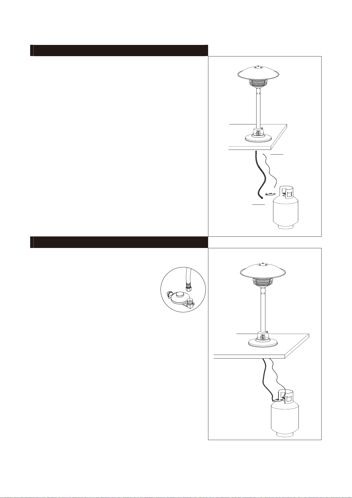
STEP 6: STEP 5
6-1.
6-2.
6-3
6-4. Connect the gas hose to the table heater gas inlet
connector with nut. Tighten the nut.
Join 2pcs supporting bolts & 2pcs washers to the
heater base.
Align / Insert Heater with support bolts over hole in
table.
From under the table, place table bracket over
support bolts, add washers and wing nuts then
tighten. To securely attach heater to the table.
STEP 6
Reflector
Washer
Castle nut
Washer
Table Support bolt
Washers and
Wing Nuts
Gas hose
Table Bracket
Page 11
STEP 7:
7-1.
7-2
Connect the regulator to the gas tank and
tighten it with adjustable wrench.
NOTE: This appliance operates with a gas hose and
regulator (supplied), which is designed to supply
Propane gas at a pressure of 2.75kPa. Only use the
hose and regulator supplied with the appliance.
STEP 8: STEP 7
8-2. Adjust the gas tank to a convenient position under
the table.
8-3. Check all the connections thoroughly for leakage
before use.
STEP 8
Safety Chain
Tank
(Table)
Attach the supplied regulator to the hose end
and tighten the connection with 2 spanners.
8-1 Connect safety chain to base of heater underneath
table and to gas tank.
Make bigger
Page 12
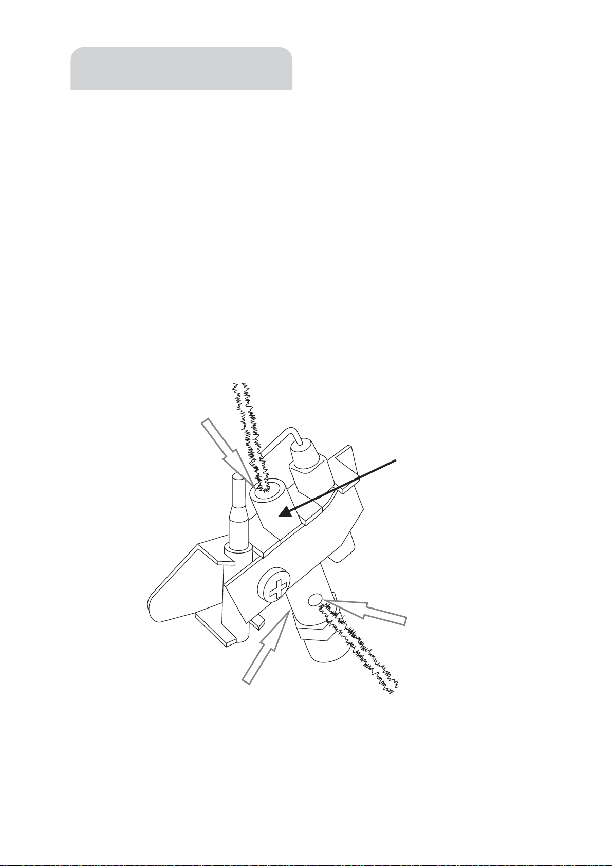
PILOT
BURNER
Insert pipe
cleaner here
Insert pipe
cleaner here
Insert pipe cleaner here
(rear air hole - where included)
7KHSLORWEXUQHUVKRXOGSURGXFHDVPDOOEOXHÀDPH,I\RXUSLORWÀDPHLVYHU\ODUJHRU
RUDQJHRUWKHSLORWÀDPHFRPHVRXWRIWKHVLGHKROHV\RXQHHGWRVHUYLFH\RXUSLORW
burner
TRVHUYLFHWKHSLORWEXUQHUUHPRYHWKHVDIHW\JXDUGWKHQUHPRYHWKHSHUIRUDWHGHPLWWHUWR
DFFHVVWKHSLORW7KHQLQVHUWDSLSHFOHDQHULQWRWKHDLUKROHVDWWKHEDVHRIWKHSLORWWXEH
and in the pilot burner tube as shown below to clear spider webVRUQHVWV
%ORZDLUWKURXJKWKHSLORWEXUQHUWXEHDQGWKURXJKWKHDLUKROHVDWWKHEDVHRIWKHSLORW
WXEHWRFOHDUWKHSLORWEXUQHURIGHDGPRWKVRUEXJV
'RQ¶WSRNHZLUHRUGULOOVLQWRWKHSLORWEXUQHUWRSUHYHQWGDPDJHWRWKHSUHFLVHJDVMHW
LQVLGHWKHSLORWWXEH
ASLORWEORFNDJHZLOOSUHYHQWQRUPDORSHUDWLRQRI\RXUKHDWHUVRUHJXODUO\FKHFN\RXUSLORW
Page 13
Pilot Service

Problem Possible cause
What you can do
(if these do not work,
contact an authorised
technician)
What ONLY an
authorised
service
technician can
do
Pilot will not light Gas valve may be OFF
Tank fuel empty
Opening blocked
Air in supply system
Low gas pressure
Not in correct location
Service pilot as shown in this manual
Purge air from the pilot gas line
Turn the gas valve ON
Check all fittings
Refill gas cylinder
Disassemble all fittings
Burner will not stay
on
Loose connections
Thermocouple bad
Gas leak in line
Lack of fuel pressure
Tank near empty
Service pilot as shown in this manual
Tighten connections
Check connections
Replace thermocouple
Refill gas cylinder
Burner flame is low Supply hose is bent or
twisted
Straighten hose and perform leak
test on hose
Emitter glows
uneven
Low gas pressure
Base is not on a level
surface
Replace cylinder with a new
cylinder
Place heater on a level surface
Thick black smoke Blockage in burner Turnoff the heater and let it cool. Remove blockage and
clear burner inside
and outside
Carbo
Gas leak at inlet
connection
Damaged or deteriorated
O-ring seal
Fit a new O-ring
n build-up Dirt or film on reflector
and flame screen
Clean reflector and flame screen
Loose connections
Trouble Shooting Check List
Page 14

Page 15
PRODUCT WARRANTY
Any claim under this warranty must be made within 12 Months of the date of
purchase of the product. To make a claim under the warranty, take the
product (with proof of purchase) to any Bunnings store (see
www.bunnings.com.au or bunnings.co.nz for store locations)
Bunnings Group Ltd bears reasonable, direct, expenses of claiming under the
warranty. You may submit details and proof to our store for consideration.
The warranty covers manufacturer defecWVLQPDWHULDOVZRUNPDQVKLSDQGÀQLVK
under normal use.
This warranty is provided in addition to other rights and remedies you may have
under law: our goods come with guarantees which cannot be excluded under
the Australian Consumer Law or Consumer Guarantees Act 1993 (NZ). You are
entitled to replacement or refund for a major failure and to compensation for
other reasonably foreseeable loss or damage. You are also entitled to have
the goods repaired or replaced if the goods fail to be of acceptable quality
and the failure does not amount to a major failure.
The warranty excludes damage resulting from product misuse or product
neglect. The warranty covers domestic use only and does not apply to
commercial applications.
This warranty is given by Bunnings Group Limited ABN 26 008 672 179, Botanicca
3 Level 2 East Tower 570 Swan Street, Burnley, VIC 312, e-mail:
Or call our Customer Support Team – Ph.1800 797 586
This warranty is given by Bunnings NZ Limited: Postal address: PO Box 14436,
Panmure, Auckland 1741,
e-mail: [email protected] Or call our Customer Support Team –
Ph.1800 797 586
Table of contents
Other Mimosa Heater manuals


