Mincey Marble Manufacturing FR-03 User manual
1
Installation Instructions for Mincey Marble Manufacturing’s
Wall Mount Foot Rest Ledge
For use with the Confetti Tile Pattern Contemporary Panel System
- FairField Inn & Suites by Marriott -
Product number: FR-03
DISCLAIMER NOTICE: If the prescribed method of installation is not followed
precisely, the foot rest may detach from the wall and cause damage to the panels
and the walls. If the foot rest ledge detaches, physical injury to the occupant of
the shower may occur. Mincey Marble will not be liable for any damages to
persons or property because of incorrect installation.
These instructions have been written for Mincey Marble’s FR-03 cast marble wall
mount foot rest ledge. If you have a different product than shown, please call us
for instructions for the product you received.
Mincey Marble Mfg., Inc.
4321 Browns Bridge Road
Gainesville, GA 30504
Ph: 800.533.1806
Fx: 770.531.0935
www.minceymarble.com
2
FR-03
Section I
Section I provides necessary details for installing the FR-03 foot rest ledge into an area that
includes wood blocking.
In preparation, before installing this foot rest ledge, you will need to have
completed the installation of the panel systems and sealed the seams of the
shower panels behind where the foot rest ledge is to be installed with 100%
silicone.
Tools /Materials Required:
1. Drill, preferably corded, for drilling holes
2. 3/16” masonry drill bit
3. Measuring tape
4. Pencil
5. 100% silicone for marble to marble seams (color matched for the marble)
6. Clean, dry cloths to clean both the foot rest ledge and wall
7. White silicone to be used for adhering the foot rest ledge to the wall
8. # 2 Phillips Head Screwdriver to tighten screws when attaching foot rest ledge (A
right-angle or ratcheting right-angle screwdriver will make the installation
easier)
9. Three #10 x 3” Stainless Steel Truss Head Sheet Metal Screws (provided by Mincey
Marble) to attach foot rest ledge to required wood blocking (supplied by
others).These screws will be packaged with the foot rest ledge.
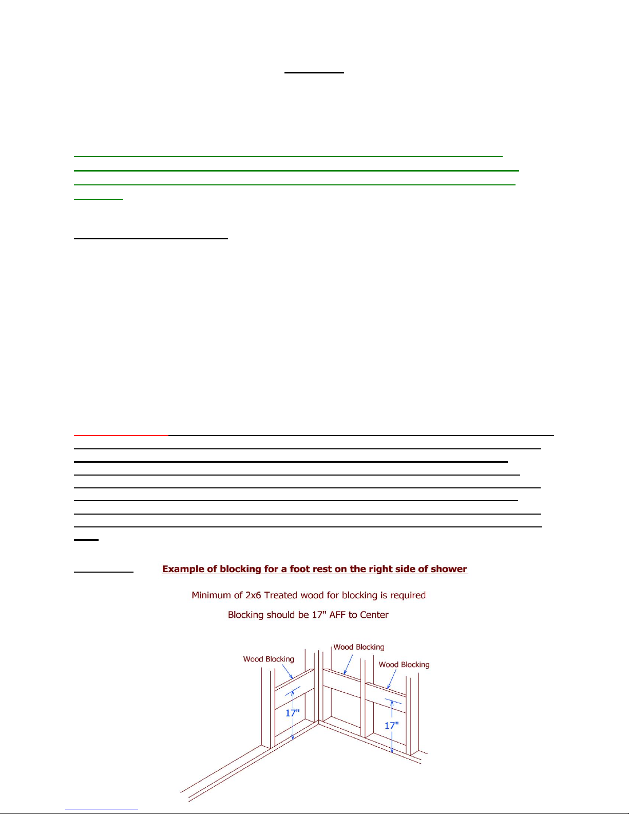
PLEASE NOTE: There should be a minimum 2 x 6 pressure treated wood blocking in the
wall behind the substrate material in the tub/shower enclosure, prior to the cast marble
panels being installed. This blocking should be installed so that the center of the
blocking will be 17” above finished floor. The blocking should be installed securely
behind the substrate on both the back wall and the end wall which is opposite from the
shower head, as the foot rest ledge will be installed in this corner of the “dry wall”.
Please see drawing (A). The wood blocking should not have any free movement and be
structurally secure behind the substrate and secured to the structural framework of the
wall.
Drawing A:
3
DISCLAIMER NOTICE: If the prescribed method of installation is not followed
precisely, the foot rest ledge may detach from the wall and cause damage to the
panels and the walls. If the foot rest ledge detaches, physical injury to the
occupant of the shower may occur. Mincey Marble will not be liable for any
damages to persons or property because of incorrect installation.
The foot rest ledge will come with pre-cut slots in the integral support, which will slide over the
truss screws in the walls. It is very important to pre-drill the holes for the truss screws into the
cast marble panels before driving the truss screws into the wood blocking, in order to avoid
damaging the cast marble panels. The integral support of the foot rest ledge has a short side
and a long side. The short side of the foot rest ledge will be installed onto the back wall and the
long side will be on the end wall of the enclosure.
Installing the Foot Rest Ledge with wood blocking:
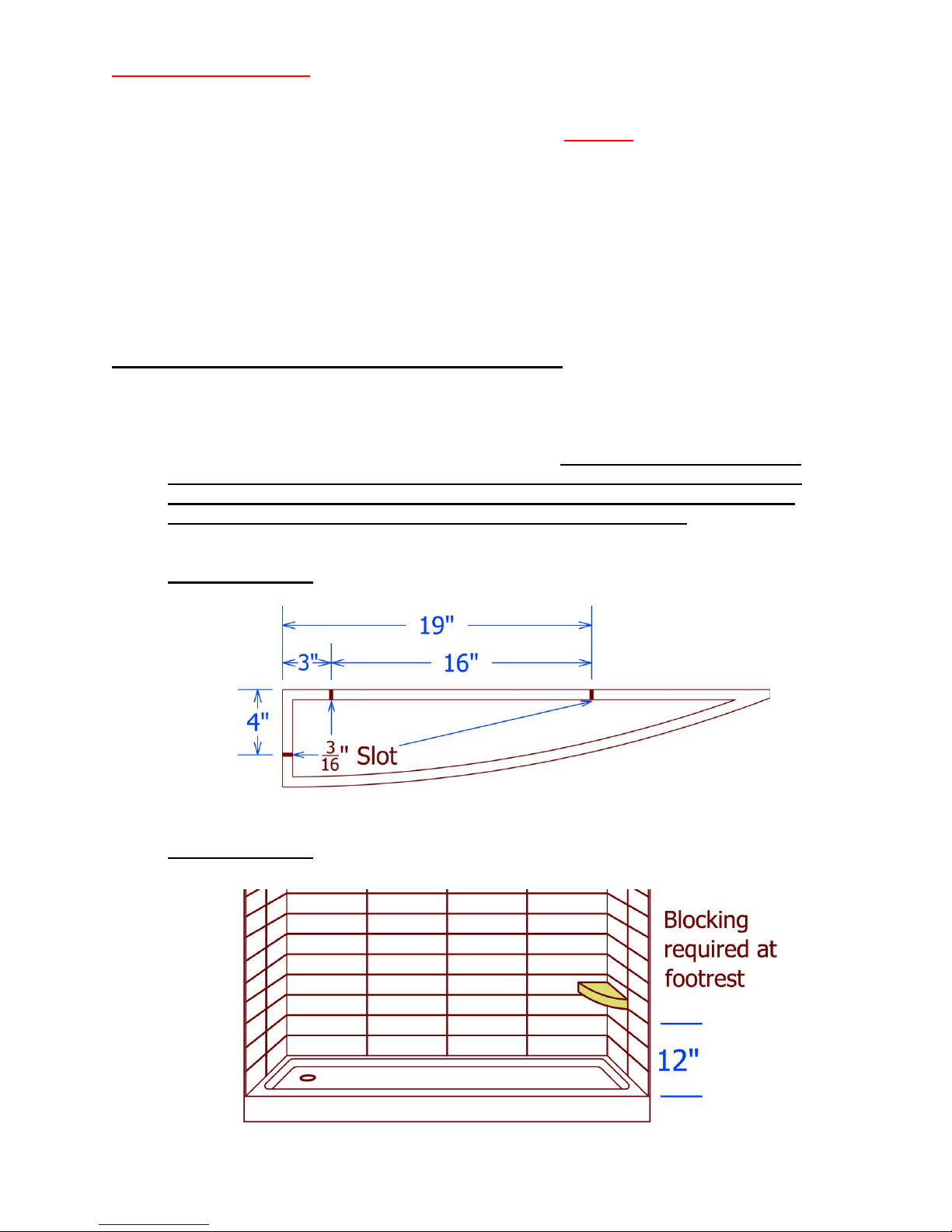
1. Measure the locations of the slots on the back of the foot rest ledge and transfer these
dimensions to the cast marble panels in the corner of the shower enclosure where the
foot rest ledge is to be installed. See illustration (1). The top of the foot rest ledge,
once installed, must be even with the top of the 1-1/2” band of the cast marble
panels. The correct location of the drilled holes is critical in order to maintain
alignment of the foot rest ledge to this band. See illustration (2).
ILLUSTRATION 1:
ILLUSTRATION 2:
4
2. Using a corded drill and a 3/16” masonry drill bit, pre-drill the cast marble panels, being
careful to avoid drilling into the wood blocking.
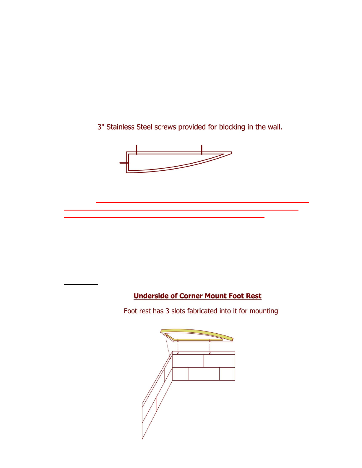
3. Drive the # 10 Stainless Steel Truss Head Screws (see illustration 3) into the wood
blocking, being sure to keep the screws level with each other and perpendicular to the
cast marble shower panels. Leave about 1” of space between the inside of the truss
head and the cast stone panels. Please note: The screws will be tightened after the foot
rest ledge has been put onto the wall)
ILLUSTRATION 3:
4. Apply 100% silicone to the entire back of the foot rest ledge, using a minimum ¼” bead
of silicone. This step cannot be skipped or avoided, as the silicone adhesive is a
necessary product in the installation of the foot rest ledge as the truss head
screws are not designed to be a stand alone installation product.
5. Slide the foot rest ledge over the Truss Head Screws and press firmly into place. See
drawing (B). Be sure to clean up any silicone that is smeared onto the wall during this
process, as soon as you have secured the foot rest ledge in place. A clean dry rag
should be all that is needed, but acetone or mineral spirits can be used on a rag to clean
up excess silicone.
Drawing B:
5
6. Using a # 2 Phillips head screwdriver, tighten the truss head screws as tightly as
possible. You will hear creaking noises when the screw is tight against the support of the
foot rest ledge. A right-angle screwdriver will make it easier to turn the screws. A
ratcheting right-angle screw driver is optimal for this installation.
7. Once the truss head screws have been tightened, try to move the foot rest ledge by
applying pressure with your hands to the foot rest ledge. If there is any movement, re-
tighten the screws until movement stops.
8. Apply color matching silicone around the perimeter of the foot rest ledge to seal the foot
rest ledge to the cast marble panels. This seal should go around the entire perimeter of
the foot rest ledge, even under the bottom of the foot rest ledge.
DISCLAIMER NOTICE: If the prescribed method of installation is not followed
precisely, the foot rest ledge may detach from the wall and cause damage to the
panels and the walls. If the foot rest ledge detaches, physical injury to the
occupant of the shower may occur. Mincey Marble will not be liable for any
damages to persons or property because of incorrect installation.
For complete information on installing the foot rest ledge into an area which DOES NOT
have wood blocking, please see Section II.
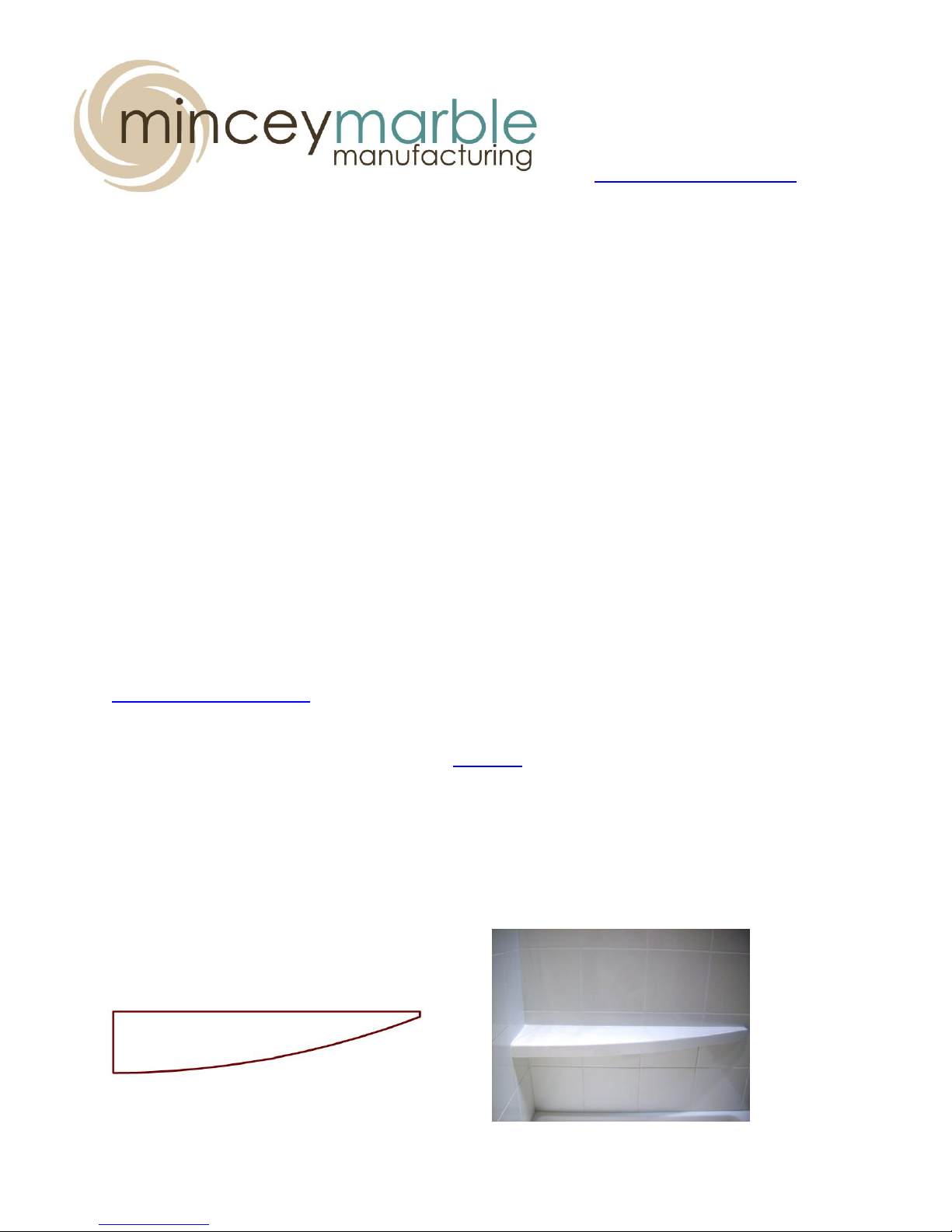
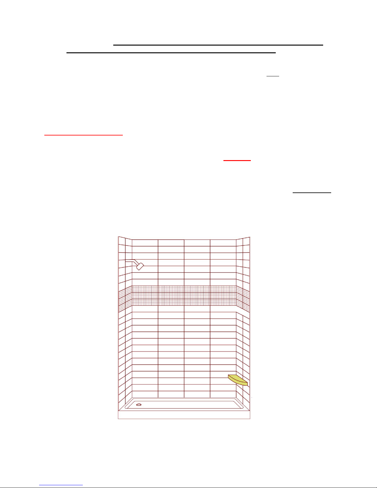
The completed installation of the panel system shower pan and foot rest ledge should
look like the following:
If you have any questions, please call Mincey Marble Customer Service at 800.533.1806
Other Mincey Marble Manufacturing Indoor Furnishing manuals


Popular Indoor Furnishing manuals by other brands

Regency
Regency LWMS3015 Assembly instructions

Furniture of America
Furniture of America CM7751C Assembly instructions

Safavieh Furniture
Safavieh Furniture Estella CNS5731 manual

PLACES OF STYLE
PLACES OF STYLE Ovalfuss Assembly instruction

Trasman
Trasman 1138 Bo1 Assembly manual

Costway
Costway JV10856 manual


