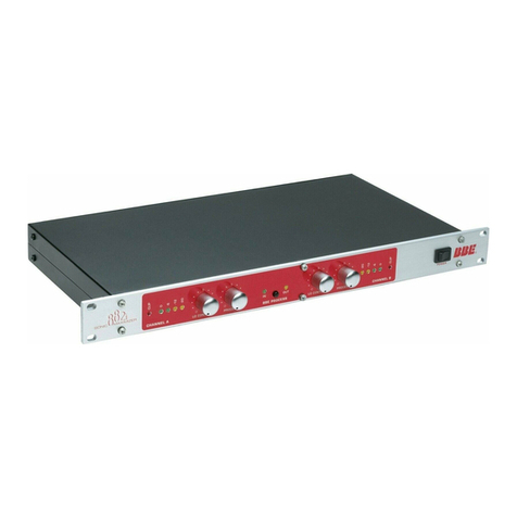
MINDPRINT DTC User manual

MANUAL
ENGLISH
www.mindprint.com
MANUAL
1.0
DTC_BDA_1.1 14.01.2002 16:32 Uhr Seite 1

IMPORTANT SAFETY INSTRUCTIONS
BEFORE CONNECTING, READ INSTRUCTIONS
• Read all of these instructions!
• Save these instructions for later use!
• Follow all warnings and instructions marked on the product!
• Do not use this product near water, i.e. bathtub, sink, swimming pool, wet basement, etc.
• Do not place this product on an unstable cart, stand or table. The product may fall, causing
serious damage to the product or to persons!
• Slots and openings in the cabinet and the back or bottom are provided for ventilation; to
ensure reliable operation of the product and to protect it from overheating, these openings
must not be blocked or covered. This product should not be placed in a built-in installation
unless proper ventilation is provided.
• This product should not be placed near a source of heat such as a stove, radiator, or
another heat producing amplifier.
• Use only the supplied power supply or power cord. If you are not sure of the type of power
available, consult your dealer or local power company.
• Do not allow anything to rest on the power cord. Do not locate this product where persons
will walk on the cord.
• Never break off the ground pin on the power supply cord.
• Power supply cords should always be handled carefully. Periodically check cords for cuts or
sign of stress, especially at the plug and the point where the cord exits the unit.
• The power supply cord should be unplugged when the unit is to be unused for long periods
of time.
• If this product is to be mounted in an equipment rack, rear support should be provided.
• This product should be used only with a cart or stand that is recommended by HK AUDIO.
• Never push objects of any kind into this product through cabinet slots as they may touch
dangerous voltage points or short out parts that could result in risk of fire or electric shock.
Never spill liquid of any kind on the product.
• Do not attempt to service this product yourself, as opening or removing covers may expose
you to dangerous voltage points or other risks. Refer all servicing to qualified service
personnel.
• Unplug this product from the wall outlet and refer servicing to qualified service personnel
under the following conditions:
• When the power cord or plug is damaged or frayed.
• If liquid has been spilled into the product.
• If the product has been exposed to rain or water.
• If the product does not operate normally when the operating instructions are followed.
• If the product has been dropped or the cabinet has been damaged.
• If the product exhibits a distinct change in performance, indicating a need of service!
• Adjust only these controls that are covered by the operating instructions since improper
adjustment of other controls may result in damage and will often require extensive work by
a qualified technician to restore the product to normal operation.
• Exposure to extremely high noise levels may cause a permanent hearing loss.
• Individuals vary considerably in susceptibility to noise induced hearig loss, but nearly
everyone will lose some hearing if exposed to sufficiently intense noise for a sufficient time.
The U.S. Government´s Occupational Safety and Health Administration (OSHA) has specified
the following permissible noise level exposures:
Duration Per Day In Hours Sound LeveldBA, Slow Response
890
692
495
397
2 100
11/2102
1 105
1/2110
1/4 or less 115
• According to OSHA, any exposure in excess of the above permissible limits could result in
some hearing loss.
• Ear plug protectors in the ear canals or over the ears must be worn when operating this
amplification system in order to prevent a permanent hearing loss if exposure is in excess
of the limits as set forth above. To ensure against potentially dangerous exposure to high
sound pressure levels, it is recommended that all persons exposed to equipment capable of
producing high sound pressure levels such as this amplification system be protected by
hearing protectors while this unit is in operation.
• Fuses: Replace with IEC 127 (5x 20 mms) type and rated fuse for best performance only.
TO PREVENT THE RISK OF FIRE AND SHOCK HAZARD, DO NOT EXPOSE THIS APPLIANCE TO
MOISTURE OR RAIN. DO NOT OPEN CASE; NO USER SERVICE-ABLE PARTS INSIDE.
REFER SERVICING TO QUALIFIED SERVICE PERSONNEL.
WICHTIGE SICHERHEITSHINWEISE!
BITTE VOR GEBRAUCH LESEN UND FÜR SPÄTEREN GEBRAUCH AUFBEWAHREN!
• Das Gerät wurde von HK AUDIO gemäß IEC 9239 gebaut und hat das Werk in sicherheits-
technisch einwandfreiem Zustand verlassen. Um diesen Zustand zu erhalten und einen
gefahrlosen Betrieb sicherzustellen, muß der Anwender die Hinweise und die Warnvermerke
beachten, die in der Bedienungsanleitung enthalten sind. Das Gerät entspricht der
Schutzklasse I (schutzgeerdet).
• DIE SICHERHEIT, ZUVERLÄSSIGKEIT UND LEISTUNG DES GERÄTES WIRD VON
HK AUDIO NUR DANN GEWÄHRLEISTET, WENN:
• Montage, Erweiterung, Neueinstellung, Änderungen oder Reparaturen von HK AUDIO oder
von dazu ermächtigten Personen ausgeführt werden.
• die elektrische Installation des betreffenden Raumes den Anforderungen von IEC (ANSI)-
Festlegungen entspricht.
• das Gerät in Übereinstimmung mit der Gebrauchsanweisung verwendet wird.
WARNUNG:
• Wenn Abdeckungen geöffnet oder Gehäuseteile entfernt werden, außer wenn dies von Hand
möglich ist, können Teile freigelegt werden, die Spannung führen.
• Wenn ein Öffnen des Gerätes erforderlich ist, muß das Gerät von allen Spannungsquellen
getrennt sein. Berücksichtigen Sie dies vor dem Abgleich, vor einer Wartung, vor einer
Instandsetzung und vor einem Austausch von Teilen.
• Ein Abgleich, eine Wartung oder eine Reparatur am geöffneten Gerät unter Spannung darf
nur durch eine vom Hersteller autorisierte Fachkraft (nach VBG 4) geschehen, die mit den
verbundenen Gefahren vertraut ist.
• Lautsprecher-Ausgänge, die mit dem IEC 417/5036-Zeichen (Abb.1, s.unten) versehen sind
können berührungsgefährliche Spannungen führen. Deshalb vor dem Einschalten des
Gerätes Verbindung nur mit dem vom Hersteller empfohlenen Anschlußkabel zum
Lautsprecher herstellen.
• Alle Stecker an Verbindungskabeln müssen mit dem Gehäuse verschraubt oder verriegelt
sein, sofern möglich.
• Es dürfen nur Sicherungen vom angegebenen Typ und der angegebenen Nennstromstärke als
Ersatz verwendet werden.
• Eine Verwendung von geflickten Sicherungen oder Kurzschließen des Halters ist unzulässig.
• Niemals die Schutzleiterverbindung unterbrechen.
• Oberflächen, die mit dem „HOT“-Zeichen (Abb.2, s.unten) versehen sind, Rückwände oder
Abdeckungen mit Kühlschlitzen, Kühlkörper und deren Abdeckungen, sowie Röhren und
deren Abdeckungen können im Betrieb erhöhte Temperaturen annehmen und sollten deshalb
nicht berührt werden.
• Hohe Lautstärkepegel können dauernde Gehörschäden verursachen. Vermeiden Sie deshalb
die direkte Nähe von Lautsprechern, die mit hohen Pegeln betrieben werden. Verwenden Sie
einen Gehörschutz bei dauernder Einwirkung hoher Pegel.
NETZANSCHLUSS:
• Das Gerät ist für Dauerbetrieb ausgelegt.
• Die eingestellte Betriebsspannung muß mit der örtlichen Netzspannung übereinstimmen.
• Der Anschluß an das Stromnetz erfolgt mit dem mitgelieferten Netzteil oder Netzkabel.
• Netzteil: Eine beschädigte Anschlußleitung kann nicht ersetzt werden. Das Netzteil darf
nicht mehr betrieben werden.
• Vermeiden Sie einen Anschluß an das Stromnetz in Verteilerdosen zusammen mit vielen
anderen Stromverbrauchern.
• Die Steckdose für die Stromversorgung muß nahe am Gerät angebracht und leicht
zugänglich sein.
AUFSTELLUNGSORT:
• Das Gerät sollte nur auf einer sauberen, waagerechten Arbeitsfläche stehen.
• Das Gerät darf während des Betriebs keinen Erschütterungen ausgesetzt sein.
• Feuchtigkeit und Staub sind nach Möglichkeit fernzuhalten.
• Das Gerät darf nicht in der Nähe von Wasser, Badewanne, Waschbecken, Küchenspüle,
Naßraum, Swimmingpool oder feuchten Räumen betrieben werden. Keine mit Flüssigkeit
gefüllten Gegenstände -Vase, Gläser, Flaschen etc. auf das Gerät stellen.
• Sorgen Sie für ausreichende Belüftung der Geräte.
• Eventuelle Ventilationsöffnungen dürfen niemals blockiert oder abgedeckt werden. Das
Gerät muß mindestens 20 cm von Wänden entfernt aufgestellt werden. Das Gerät darf nur
dann in ein Rack eingebaut werden, wenn für ausreichende Ventilation gesorgt ist und die
Einbauanweisungen des Herstellers eingehalten werden.
• Vermeiden Sie direkte Sonneneinstrahlung sowie die unmittelbare Nähe von Heizkörpern
und Heizstrahlern oder ähnlicher Geräte.
• Wenn das Gerät plötzlich von einem kalten an einen warmen Ort gebracht wird, kann sich
im Geräteinnern Kondensfeuchtigkeit bilden. Dies ist insbesondere bei Röhrengeräten zu
beachten. Vor dem Einschalten solange warten bis das Gerät Raumtemperatur angenommen
hat.
• Zubehör: Das Gerät nicht auf einen instabilen Wagen, Ständer, Dreifuß, Untersatz oder Tisch
stellen. Wenn das Gerät herunterfällt, kann es Personenschäden verursachen und selbst
beschädigt werden. Verwenden Sie das Gerät nur mit einem vom Hersteller empfohlenen
oder zusammen mit dem Gerät verkauften Wagen, Rack, Ständer, Dreifuß oder Untersatz. Bei
der Aufstellung des Gerätes müssen die Anweisungen des Herstellers befolgt und muß das
vom Hersteller empfohlene Aufstellzubehör verwendet werden. Eine Kombination aus Gerät
und Gestell muß vorsichtigt bewegt werden. Plötzliches Anhalten, übermäßige
Kraftanwendung und ungleichmäßige Böden können das Umkippen der Kombination aus
Gerät und Gestell bewirken.
• Zusatzvorrichtungen: Verwenden Sie niemals Zusatzvorrichtungen, die nicht vom Hersteller
empfohlen wurden, weil dadurch Unfälle verursacht werden können
• Zum Schutz des Gerätes bei Gewitter oder wenn es längere Zeit nicht beaufsichtigt oder
benutzt wird, sollte der Netzstecker gezogen werden. Dies verhindert Schäden am Gerät
aufgrund von Blitzschlag und Spannungsstößen im Wechselstromnetz.
Abb.1 Abb.2
2
DTC_BDA_1.1 14.01.2002 16:32 Uhr Seite 2

IMPORTANT ADVICE ON SAFETY!
PLEASE READ BEFORE USE AND KEEP FOR LATER USE!
• The unit has been built by HK AUDIO in accordance with IEC 9239 and left the factory in
safe working order. To maintain this condition and ensure non-risk operation, the user must
follow the advice and warning comments found in the operating instructions. The unit
conforms to Protection Class 1 (protectively earthed).
• HK AUDIO ONLY GUARANTEE THE SAFETY, RELIABILITY AND EFFICIENCY OF THE UNIT IF:
• Assembly, extension, re-adjustment, modifications or repairs are carried out by HK AUDIO or
by persons authorized to do so.
• The electrical installation of the relevant area complies with the requirements of IEC (ANSI)
specifications.
• The unit is used in accordance with the operating instructions.
• The unit is regularly checked and tested for electrical safety by a competent technician.
WARNING:
• If covers are opened or sections of casing are removed, except where this can be done
manually, live parts can become exposed.
• If it is necessary to open the unit this must be isolated from all power sources. Please take
this into account before carrying out adjustments, maintenance, repairs and before
replacing parts.
• Adjustment, maintenance and repairs carried out when the unit has been opened and is still
live may only be performed by specialist personnel who are authorized by the manufacturer
(in accordance with VBG 4) and who are aware of the associated hazards.
• Loudspeaker outputs which have the IEC 417/5036 symbol (Diagram 1, below) can carry
voltages which are hazardous if they are made contact with. Before the unit is switched on,
the loudspeaker should therefore only be connected using the lead recommended by the
manufacturer.
• Where possible, all plugs on connection cables must be screwed or locked onto the casing.
• Replace with IEC 127 (5x 20 mms) type and rated fuse for best performance only.
• It is not permitted to use repaired fuses or to short-circuit the fuse holder.
• Never interrupt the protective conductor connection.
• Surfaces which are equipped with the „HOT“ mark (Diagram 2, below), rear panels or
covers with cooling slits, cooling bodies and their covers, as well as tubes and their covers
are purposely designed to dissipate high temperatures and should therefore not be touched.
• High loudspeaker levels can cause permanent hearing damage. You should therefore avoid
the direct vicinity of loudspeakers operating at high levels. Wear hearing protection if
continuously exposed to high levels.
MAINS CONNECTION:
• The unit is designed for continuous operation.
• The set operating voltage must match the local mains supply voltage.
• The unit is connected to the mains via the supplied power unit or power cable.
• Power unit: Never use a damaged connection lead. Any damage must be rectified by a
competent technician.
• Avoid connection to the mains supply in distributor boxes together with several other
power consumers.
• The plug socket for the power supply must be positioned near the unit and must be easily
accessible.
PLACE OF INSTALLATION:
• The unit should stand only on a clean, horizontal working surface.
• The unit must not be exposed to vibrations during operation.
• Keep away from moisture and dust where possible.
• Do not place the unit near water, baths, wash basins, kitchen sinks, wet areas, swimming
pools or damp rooms. Do not place objects containing liquid on the unit - vases, glasses,
bottles etc.
• Ensure that the unit is well ventilated.
• Any ventilation openings must never be blocked or covered. The unit must be positioned at
least 20 cm away from walls. The unit may only be fitted in a rack if adequate ventilation is
ensured and if the manufacturer’s installation instructions are followed.
• Keep away from direct sunlight and the immediate vicinity of heating elements and radiant
heaters or similar devices.
• If the unit is suddenly moved from a cold to a warm location, condensation can form inside
it. This must be taken into account particularly in the case of tube units. Before switching
on, wait until the unit has reached room temperature.
• Accessories: Do not place the unit on an unsteady trolley, stand, tripod, base or table. If the
unit falls down, it can cause personal injury and itself become damaged. Use the unit only
with the trolley, rack stand, tripod or base recommended by the manufacturer or purchased
together with the unit. When setting the unit up, all the manufacturer’s instructions must be
followed and the setup accessories recommended by the manufacturer must be used. Any
combination of unit and stand must be moved carefully. A sudden stop, excessive use of
force and uneven floors can cause the combination of unit and stand to tip over.
• Additional equipment: Never use additional equipment which has not been recommended
by the manufacturer as this can cause accidents.
• To protect the unit during bad weather or when left unattended for prolonged periods, the
mains plug should be disconnected. This prevents the unit being damaged by lightning and
power surges in the AC mains supply.
Diagram 1 Diagram 2
CONSEILS DE SECURITE IMPORTANTS!
PRIERE DE LIRE AVANT L’EMPLOI ET A CONSERVER POUR UTILISATION ULTERIEURE!
• L’appareil a été conçu par HK AUDIO selon la norme IEC 9239 et a quitté l’entreprise dans
un état irréprochable. Afin de conserver cet état et d’assurer un fonctionnement sans
danger de l’appareil nous conseillons à l’utilisateur la lecture des indications de sécurité
contenues dans le mode d’emploi. L’appareil est conforme à la classification I (mise à terre
de protection).
• SURETE, FIABILITE ET EFFICACITE DE L’APPAREIL NE SONT GARANTIS PAR HK AUDIO QUE SI:
• Montage, extension, nouveau réglage, modification ou réparation sont effectués par
HK AUDIO ou par toute personne autorisée par HK AUDIO.
• L’installation électrique de la pièce concernée correspond aux normes IEC (ANSI).
• L’utilisation de l’appareil suit le mode d’emploi.
AVERTISSEMENT:
• A moins que cela ne soit manuellement possible, tout enlèvement ou ouverture du boîtier
peut entrainer la mise au jour de pieces sous tension.
• Si l’ouverture de l’appareil est nécessaire, celui-ci doit être coupé de chaque source de
courant. Ceci est à prendre en considération avant tout ajustement, entretien, réparation ou
changement de pieces.
• Ajustement, entretien ou réparation sur l’appareil ouvert et sous tension ne peuvent être
éffectués que par un spécialiste autorisé par le fabricant (selon VBG4). Le spécialiste étant
conscient des dangers liés à ce genre de réparation.
• Les sorties de baffles qui portent le signe IEC 417/5036 (fig. 1, voir en bas) peuvent être
sous tension dangereuse. Avant de brancher l’appareil utiliser uniquement le câble de
raccordement conseillé par le fabricant pour raccorder les baffles.
• Toutes les prises des câbles de raccordement doivent être, si possible, vissées ou
verrouillées sur le boîtier.
• Utilisez subsidiairement uniquement des fusibles de type et de puissance de courant
nominale donnés.
• L’utilisation de fusibles rafistolés ou court-circuites est inadmissible.
• Ne jamais interrompre la connexion du circuit protecteur.
• Il est conseillé de ne pas toucher aux surfaces pourvues du signe „HOT“ (fig. 2, voir en
bas), aux parois arrières ou caches munis de fentes d’aération, éléments d’aération et leurs
caches ansi qu’aux tubes et leurs caches. Ces éléments pouvant atteindre des températures
élévées pendant l’utilisation de l’appareil.
• Les Niveaux de puissance élévés peuvent entrainer des lésions auditives durables. Evitez
donc la proximité de haut-parleurs utilisés à haute puissance. Lors de haute puissance
continue utilisez une protection auditive.
BRANCHEMENT SUR LE SECTEUR:
• L’appareil est conçu pour une utilisation continue.
• La tension de fonctionnement doit concorder avec la tension secteur locale.
• Le raccordement au réseau éléctrique s’effectue avec l’adaptateur ou le cordon
d´alimentation livré avec l’appareil.
• Adaptateur: Un câble de raccordement abimé ne peut être remplacé. L’adaptateur est
inutilisable.
• Evitez un raccordement au réseau par des boîtes de distribution surchargées.
• La prise de courant doit être placée à proximité de l’appareil et facile à atteindre.
LIEU D’INSTALLATION:
• L’appareil doit être placé sur une surface de travail propre et horizontale.
• L’appareil en marche ne doit en aucun cas subir des vibrations.
• Evitez dans la mesure du possible poussière et humidité.
• L’appareil ne doit pas être placé à proximité d’eau, de baignoire, lavabo, évier, pièce d’eau,
piscine ou dans une pièce humide. Ne placez aucun vase, verre, bouteille ou tout objet
rempli de liquide sur l’appareil.
• L’appareil doit être suffisamment aéré.
• Ne jamais recouvrir les ouvertures d’aération. L’appareil doit être placé à 20 cm du mur au
minimum. L’appareil peut être monté dans un Rack si une ventilation suffisante est possible
et si les conseils de montage du fabricant sont suivis.
• Evitez les rayons de soleil et la proximité de radiateurs, chauffages etc.
• Une condensation d’eau peut se former dans l’appareil si celui-ci est transporté
brusquement d’un endroit froid à un endroit chaud. Ceci est particulièrement important
pour des appareils à tubes. Avant de brancher l’appareil attendre qu’il ait la température
ambiante.
• Accessoires: L’appareil ne doit être placé sur un chariot, support, trépied, bâti ou table
instable. Une chute de l’appareil peut entrainer aussi bien des dommages corporels que
techniques. Utilisez l’appareil uniquement avec un chariot, Rack, support, trépied ou bâti
conseillé par le fabricant ou vendu en combinaison avec l’appareil. Les indications du
fabricant pour l’installation de l’appareil sont à suivre, et les accessoires d’installation
conseillés par le fabricant sont à utiliser. Un ensemble support et appareil doit être déplacé
avec précaution. Des mouvements brusques et des revêtements de sol irreguliers peuvent
entrainer la chute de l´ensemble.
• Equipements supplémentaires: Ne jamais utiliser un équipement supplémentaire n’ayant pas
été conseillé par le fabricant, ceci pouvant entrainer des accidents.
• Afin de protéger l’appareil pendant un orage ou s’il ne doit pas être utilisé pendant un
certain temps, il est conseillé d’enlever la prise au secteur. Ceci évite des dommages dûs à
la foudre ou à des coups de tension dans le réseau à courant alternatif.
Fig. 1 Fig. 2
3
DTC_BDA_1.1 14.01.2002 16:32 Uhr Seite 3

IMPORTANTI AVVERTIMENTI DI SICUREZZA!
Leggere attentamente prima dell’uso e conservare per un utilizzo successivo:
• L’apparecchio è stato costruito dalla HK AUDIO secondo la normativa europea IEC 9239 ed
ha lasciato il nostro stabilimento in stato ineccepibile. Per garantire il mantenimento di tale
stato e un utilizzo assolutamente privo di rischi l’utente è tenuto ad osservare le indicazioni
e gli avvertimenti di sicurezza contenuti nelle istruzioni per l’uso. L’apparecchio rispecchia il
livello di sicurezza I (collegato a terra).
• Sicurezza, affidabilità e prestazioni dell’apparecchio vengono garantiti dalla HK AUDIO solo
ed esclusivamente se:
• Montaggio, ampliamento, rimessa a punto, modifiche e riparazioni vengono eseguite dalla
HK AUDIO stessa o da personale da essa autorizzato.
• Gli impianti elettrici nei locali prescelti per l’uso dell’apparecchio rispondono alle normative
stabilite dall’ANSI.
• L’apparecchio viene utilizzato come indicato nel libretto delle istruzioni per l’uso.
Avvertimenti:
• In caso di apertura di parti di rivestimento o rimozione di parti dell’involucro, a meno che
non si tratti di pezzi rimovibili semplicemente a mano, possono venire alla luce parti
dell’apparecchio conduttrici di tensione.
• Se l’apertura dell’apparecchio dovesse risultare necessaria è indispensabile staccare
precedentemente quest’ultimo da tutte le fonti di tensione. Rispettare tale misura di
prevenzione anche prima di un allineamento, di operazioni di manutenzione, della messa in
esercizio o della sostituzione di componenti all’interno dell’apparecchio.
• Allineamento, operazioni di manutenzione o eventuali riparazioni dell’apparecchio in pre-
senza di tensione vanno eseguite esclusivamente da personale specializzato ed autorizzato,
in grado di eseguire tali operazioni evitandone i rischi connessi.
• Le uscite degli altoparlanti contrassegnate dai caratteri IEC 417/5036 (vedi illustrazione 1 a
fondo pag.) possono essere conduttrici di tensione pericolosa con cui evitare il contatto. Per
questo motivo, prima di accendere l’apparecchio, collegare quest’ultimo agli altoparlanti
servendosi esclusivamente del cavetto d’allacciamento indicato dal produttore.
• Tutte le spine e i cavi di collegamento devono essere avvitati o fissati all’involucro
dell’apparecchio per quanto possibile.
• Tutti i fusibili di sicurezza vanno sostituiti esclusivamente con fusibili del tipo prescritto e
valore della corrente nominale indicato.
• L’utilizzo di fusibili di sicurezza non integri e la messa in corto circuito del sostegno di
metallo sono proibite.
• Non interrompere mai il collegamento con il circuito di protezione.
• Superfici contrassegnate dalla parola „HOT“ (vedi illustrazione 2 a fondo pag.), cosi come
griglie di aerazione, dispositivi di raffreddamento e i loro rivestimenti di protezione, oppure
valvole e i relativi rivestimenti protettivi possono surriscaldarsi notevolmente durante l’uso
e per questo motivo non vanno toccate.
• L’ascolto di suoni ad alto volume può provocare danni permanenti all’udito. Evitate perciò
la diretta vicinanza con altoparlanti ad alta emissione di suono e utilizzate cuffie protettive
in caso ciò non sia possibile.
Alimentazione:
• L’apparecchio è concepito per il funzionamento continuo.
• La tensione di esercizio deve corrispondere alla tensione di rete a cui ci si allaccia.
• L’allacciamento alla rete elettrica avviene tramite alimentatore o cavetto d’alimentazione
consegnato insieme all’apparecchio.
• Alimentatore: un cavo di connessione danneggiato non può essere sostituito. L’alimentatore
non può più essere utilizzato.
• Evitate un allacciamento alla rete di corrente utilizzando cassette di distribuzione
sovraccariche.
• La spina di corrente deve essere situata nelle vicinanze dell’apparecchio e facilmente
raggiungibile in qualsiasi momento.
Locali di collocamento:
• Opportuno collocare l’apparecchio su una superficie pulita e orizzontale.
• Non sottoporre l’apparecchio in funzione a scosse e vibrazioni.
• Proteggere l’apparecchio per quanto possibile da umidità e polvere.
• Non collocare l’apparecchio vicino ad acqua, vasche da bagno, lavandini, lavelli da cucina,
locali umidi o piscine. Non appoggiare recipienti contenenti liquidi - vasi, bicchieri,
bottiglie, ecc. - sull’apparecchio.
• Provvedere ad una buone aerazione dell’apparecchio.
• Eventuali aperture previste per la ventilazione dell’apparecchio non vanno ne bloccate, ne
mai coperte. L’apparecchio va collocato ad almeno 20 cm di distanza dalle pareti circostanti
e può essere inserito tra altre componenti di un impianto solo in caso di sufficiente
ventilazione e qualora le direttive di montaggio del produttore vengano rispettate.
• Evitare di esporre l’apparecchio ai raggi del sole e di collocarlo direttamente nelle vicinanze
di fonti di calore come caloriferi, stufette, ecc.
• Se l’apparecchio viene trasportato rapidamente da un locale freddo ad uno riscaldato può
succedere che al suo interno si crei della condensa. Ciò va tenuto in considerazione
soprattutto in caso di apparecchi a valvole. Attendere che l’apparecchio abbia assunto la
temperatura ambiente prima di accenderlo.
• Accessori: non collocare l’apparecchio su carrelli, supporti, treppiedi, superfici o tavoli
instabili. Se l’apparecchio dovesse cadere a terra potrebbe causare danni a terzi o
danneggiarsi irreparabilmente. Utilizzate per il collocamento dell’apparecchio supporti,
treppiedi e superfici che siano consigliate dal produttore o direttamente comprese
nell’offerta di vendita. Per il collocamento dell’apparecchio attenetevi strettamente alle
istruzioni del produttore, utilizzando esclusivamente accessori da esso consigliati.
L’apparecchio in combinazione ad un supporto va spostato con molta attenzione. Movimenti
bruschi o il collocamento su pavimenti non piani possono provocare la caduta
dell’apparecchio e del suo supporto.
• Accessori supplementari: non utilizzate mai accessori supplementari che non siano
consigliati dal produttore, potendo essere ciò causa di incidenti.
• Per proteggere l’apparecchio in caso di temporali o nel caso questo non venisse utilizzato
per diverso tempo si consiglia di staccarne la spina di corrente. In questo modo si evitano
danni all’apparecchio dovuti a colpi di fulmine o ad improvvisi aumenti di tensione nel
circuito di corrente alternata.
Illustrazione 1 Illustrazione 2
¡INDICACIONES DE SEGURIDAD IMPORTANTES!
¡LÉANSE ANTES DE UTILIZAR EL APARATO Y GUARDENSE PARA SU USO POSTERIOR!
• El aparato ha sido producido por HK AUDIO según el IEC 9239 y salió de la fábrica en un
estado técnicamente perfecto. Para conservar este estado y asegurar un funcionamiento sin
peligros el usuario debe tener en cuenta las indicaciones y advertencias contenidas en las
instrucciones de manejo. El aparato corresponde a la clase de protección l (toma de tierra
protegida).
• LA SEGURIDAD, LA FIABILIDAD Y EL RENDIMIENTO DEL APARATO SOLO ESTAN
GARANTIZADOS POR HK AUDIO CUANDO:
• el montaje, la ampliación, el reajuste, los cambios o las reparaciones se realicen por
HK AUDIO o por personas autorizadas para ello;
• la instalación eléctrica del recinto en cuestión corresponda a los requisitos de la
determinación del IEC (ANSI);
• el aparato se use de acuerdo con las indicaciones de uso.
ADVERTENCIA:
• Si se destapan protecciones o se retiran piezas de la carcasa, exceptuando si se puede
hacer manualmente, se pueden dejar piezas al descubierto que sean conductoras de
tensión.
• Si es necesario abrir el aparato, éste tiene que estar aislado de todas las fuentes de
alimentación. Esto se debe tener en cuenta antes del ajuste, de un entretenimiento, de una
reparación y de una sustitución de las piezas.
• Un ajuste, un entretenimiento o una reparación en el aparato abierto y bajo tensión sólo
puede ser llevado a cabo por un especialista autorizado por el productor (según VBG 4) que
conozca a fondo los peligros que ello conlleva.
• Las salidas de altavoces que estén provistas de la característica IEC 417/5036 (figura 1,
véase abajo) pueden conducir tensiones peligrosas al contacto. Por ello es indispensable
que antes de poner en marcha el aparato; la conexión se haya realizado únicamente con el
cable de empalmes recomendado por el productor.
• Las clavijas de contacto al final de los cables conectores tienen que estar atornilladas o
enclavadas a la carcasa, en tanto que sea posible.
• Los fusibles de repuesto que se utilicen sólo pueden ser del tipo indicado y tener la
intensidad nominal indicada.
• El uso de fusibles reparados o la puesta en cortocircuito del soporte es inadmisible.
• El empalme del conductor de protección no se puede interrumpir en ningún caso.
• Las superficies provistas de la característica "HOT" (figura 2, véase abajo), los paneles de
fondo trasero o las protecciones con ranuras de ventilación, los cuerpos de ventilación y sus
protecciones, así como las válvulas electrónicas y sus protecciones pueden alcanzar
temperaturas muy altas durante el funcionamiento y por ello no se deberían tocar.
• Niveles elevados de la intensidad de sonido pueden causar continuos daños auditivos; por
ello debe evitar acercarse demasiado a altavoces que funcionen a altos niveles. En tales
casos utilice protecciones auditivas.
ACOMETIDA A LA RED:
• El aparato está proyectado para un funcionamiento continuo.
• La tensión de funcionamiento ajustada tiene que coincidir con la tensión de la red del lugar.
• La conexión a la red eléctrica se efectuará con la fuente de alimentación o con el cable de
red que se entreguen con el aparato.
• Fuente de alimentación: una linea de conexión dañada no se puede sustituir. La fuente de
alimentación no puede volver a ponerse en funcionamiento.
• Evite una conexión de la red eléctrica a distribuidores con muchas tomas de corriente.
• El enchufe para el suministro de corriente tiene que estar cerca del aparato y ser de fácil
acceso.
SITUACION:
• El aparato debería estar situado en una superficie limpia y totalmente horizontal.
• El aparato no puede estar expuesto a ningún tipo de sacudidas durante su funcionamiento.
• Se deben evitar la humedad y el polvo.
• El aparato no puede ponerse en funcionamiento cerca del agua, la bañera, el lavamanos, la
pila de la cocina, un recinto con tuberías de agua, la piscina o en habitaciones húmedas.
Tampoco se pueden poner objetos llenos de líquido - jarrones, vasos, botellas, etc. - encima
de él.
• Procure que el aparato tenga suficiente ventilación.
• Las aberturas de ventilación existentes no se deben bloquear ni tapar nunca. El aparato
debe estar situado como mínimo a 20 cm de la pared. El aparato sólo se puede montar en
un rack, si se ha procurado la suficiente ventilación y se han cumplido las indicaciones de
montaje del productor.
• Evite los rayos del sol directos así como la proximidad a radiadores, electro-radiadores o
aparatos similares.
• Si el aparato pasa repentinamente de un lugar frío a otro caliente, se puede condensar
humedad en su interior. Esto se debe tener en cuenta sobretodo en los aparatos con
válvulas electrónicas. Antes de poner en marcha el aparato se debe esperar hasta que éste
haya adquirido la temperatura ambiental.
• Accesorios: el aparato no se puede colocar encima de carros, estantes, trípodes, soportes o
mesas inestables. Si el aparato se cae puede causar daños personales y se puede estropear.
Coloque el aparato sólo en un carro, rack, estante, trípode o soporte recomendado por el
productor o que se le haya vendido junto con el aparato. En la instalación se deben seguir
las indicaciones del productor así como utilizar los accesorios recomendados por el mismo
para colocarlo encima. El conjunto del aparato con el pedestal se debe mover con mucho
cuidado. Un paro brusco, la aplicación de una fuerza desmesurada o un suelo irregular
puede ocasionar la caida de todo el conjunto.
• Piezas adicionales: no utilice nunca piezas adicionales que no estén recomendadas por el
productor, ya que se podrían provocar accidentes.
• Para protejer el aparato de una tormenta o si no se supervisa ni utiliza durante algún
tiempo, se debería desconectar la clavija de la red. Así se evitan daños en el aparato a
causa de un rayo y golpes de tensión en la red de corriente alterna.
Figura 1 Figura 2
4
DTC_BDA_1.1 14.01.2002 16:32 Uhr Seite 4

Welcome!
Congratulations and thank you for choosing the MindPrint DTC™
in your search for superior sonic results.
The MindPrint Dual Tube Channel signal processor combines two high-quality microphone
preamps, equalizers and compressor/limiters in one unit, giving you all the unctionality o a
ully-loaded high-end channel strip. Its unique pairing o tried-and-true analog components
with the audio idelity o today’s advanced circuit designs will lend your recordings
unparalleled vividness and warmth. And with the optional digital inter ace in place,
the DTC™ will seamlessly it into your digital studio environment.
The people who have joined orces to comprise the MindPrint team share years o experience
rom the ields o pro audio, tube circuitry, and digital technology. In this new MindPrint
product, they have applied their collective know-how to meet the expressed wishes o
countless studio engineers the world over.
Over the past several years, modern recording equipment has achieved a very high level o
quality at continually improving prices. O ten, however, much o the real potential o the
recording is un ortunately lost due to inadequacies at either the input stage, the digital
conversion stage, or the analog circuitry used around the converter.
The DTC™ provides precisely this missing link in the signal chain, delivering those very
elements and eatures that bring out the best o your other recording equipment.
The resulting sound is more dimensional, more vivid and more truly musical.
One o the underlying design principles behind the DTC™ is optimization o the signal paths.
In each and every design decision the shortest possible signal path was chosen, bypassing
unneeded components completely.
All in all, the very e ective iltering, the opto/tube-compressor and the optional digital inputs
and outputs (24-bit/96 kHz) combine to make the DTC™ a universal processing center or
every kind o audio signal.
We wish you a great deal o enjoyment and success with your new DTC™!
St. Wendel, Germany
December 2001
5
MindPrint-DTCTM
Info
In the digital age achieving a higher level o quality is
something that is nearly impossible to do with just
higher sampling rates or bit depths. Digital
processing quality is better than ever, and has
reached a level (with the new DVD standard) that
meets even the highest sonic and dynamic
requirements. With a sampling rate o 96 kHz we can
reproduce requencies that are more than double the
highest requencies man's hearing mechanism is
capable o perceiving. A resolution o 24 bits o ers us
a dynamic range that can capture sound at pressure
levels that go ar beyond the threshold o pain o
human hearing. In the past, our attempt to
reproduce all the perceptible nuances o a sound was
severely limited by the available technology; today
we are much closer to capturing all the details o a
sound in its ull glory.
Question
Since digital technology today is capable o such
high resolution, one would think that the best and
shortest connection would be a pure analog-to-
digital converter. So why is MindPrint now
developing high-end analog technology?
Answer
Even more important than the quality o the digital
converter itsel is the quality o the analog circuitry
preceding the converter. Today the only part o the
signal chain that is subject to loss is the analog
section that prepares the signal right be ore it hits
the digital realm. The task o the DTC™ is to make
this part o the path as good and as short as possible.
The thing to keep in mind is that the sound o
instruments and microphones occur in the analog
realm, as waves and current, and not as bits and
samples. And waves and current are very sensitive as
to how they react to physical quantities such as
impedance, capacitance, and induction. And only
when we pay proper attention to these quantities,
and waves and current are turned into the "right
orm," do we stand a good chance o per orming a
proper conversion to digital. Technically speaking, the
job o the DTC™ is to take a very weak modulating
eleHigh-Zensitivity™ Trans ormer. The complex
interplay o impedance, capacitance and induction in
the input trans ormer is responsible or the optimal
matching o the microphone's diaphragm to its
electronics, and aids considerably in enabling the
microphone to reproduce sound in a natural manner.
MindPrint has researched these phenomena and
collaborated with the company Hau e to develop
a new trans ormer.
This sophisticated trans ormer possesses the
advantageous sound characteristics known rom older
models, but avoids their common side e ects, such as
phase distortion in the treble region. It can do so
because it has such an extremely broad requency
range (up to 127 kHz) that the phase distortion
occurs out o the range o human hearing.
Furthermore, because it has a turns ratio o 1:5 the
trans ormer makes li e easier or the subsequent
ampli ier stage, thereby reduces distortion and makes
it possible to achieve an extremely good signal-to-
noise ratio.
ENGLISH
Table of Contents:
1. The Input. . . . . . . . . . . . . . . . . . . . . . . . . . . . . . . . . 6
2. Equalization: Frequency Processing . . . . . . . . . . . . . 10
3. Compressor/Limiter: Dynamics Processing. . . . . . . . 14
4. The Output . . . . . . . . . . . . . . . . . . . . . . . . . . . . . . . 17
5. Technical Speci ications . . . . . . . . . . . . . . . . . . . . . . 18
6. Appendix: The Digital Option . . . . . . . . . . . . . . . . . 19
DTC_BDA_1.1 14.01.2002 16:32 Uhr Seite 5

1. The Input Section
The DTC™ has a comprehensive input section
consisting o a line-level input, an instrument
input and a microphone input. You can add
a digital input by installing the MindPrint
DI-Mod 24/96 expansion module.
1.1 Microphone input
Connections:
An XLR jack is provided on the back o the DTC™
or each channel or microphones o all types.
To accommodate condenser microphones,
48-volt phantom power can be applied rom
a switch on the ront panel.
Impedance is 5 kOhms.
Operation:
MIC IN: switches on the microphone input. This
switch has priority over all other input switches.
MIC GAIN: adjusts the input sensitivity o the
microphone signal within a range o +20 dB to
+72 dB.
-20 db: switches a passive pad o -20 dB be ore
the microphone channel preamp stage to avoid
distortion rom high-output microphones.
48 V: applies phantom power to the channel.
Warning: DO NOT turn on the 48V
phantom power with unbalanced
microphones or ribbon mics,
as these can be damaged by
the phantom power!
6
MindPrint-DTCTM
Inner workings of the
High-Zensitivity™ Transformer
Question: At 5 kOhms, the impedance o the micro-
phone input is considerably higher than normal. Why
does MindPrint deviate so greatly
rom the 600-Ohm standard?
Answer: The impedance o microphones is not a
constant but is requency dependent. Within the
requency range o microphones there exist certain
impedance peaks which can ar exceed 1000 Ohms.
I the input impedance o a microphone preamp is
less, these peaks are damped, which in e ect
automatically changes the requency response. Since
these peaks occur especially in the treble region, the
automatic damping o low-impedance preamps leads
to a loss o brilliance. The DTC™, due to its high-
impedance design, can handle even extreme peaks
and thereby avoids losses in the highs. This especially
makes dynamic microphones sound more transparent
and natural. Condenser microphones also sound
better, since their ampli iers, which are not loaded
down as much, can operate with less distortion.
ctrical signal with a very broad requency range and
ampli y it and "shape" it. But this electrical signal has
its own peculiarities: depending on whether the
induction and the capacitance is set up in the circuit
to run in parallel or in series, these can have a
damping e ect on the bass and treble. With all
analog sound sources, whether pickup or
microphone, or even a normal cable, the capacitance
and inductance play a role and in luence the sound.
The special input circuitry o the DTC™ respects them
in a very special way, so that they do have the
necessary "raw orm" required or the subsequent
requency and dynamics processing.
MIC IN A
BALANCED
DTC_BDA_1.1 14.01.2002 16:32 Uhr Seite 6

1.2 Line Input
Connections:
On the rear panel, the DTC™ includes a SEND
and RETURN jack on each channel or inserting
external signal processors into the DTC™ signal
path. The connectors are stereo-style balanced
Tip-Ring-Sleeve jacks, with the Tip hot (positive)
and the Ring cold (negative). The Sleeve is
connected to ground. When you insert an
unbalanced mono 1/4-inch plug, the RETURN
automatically switches to unbalanced
operating mode.
Operation:
LIN /INSTR GAIN: adjusts the preampli ication
level o LINE IN, INSTRUMENT IN,
and DIGITAL IN.
Note: Ensure that the MIC IN button is
not pressed in.
1.3 Instrument Input
Connections:
A 1/4-inch mono input jack or connecting
instruments is located on the ront panel o the
unit. When you insert a plug into this jack, the
Line input and the Digital input are automatically
switched o . The sensitivity o the Instrument
input was chosen so that electric guitars and bass
guitars could be connected directly.
Operation:
LIN /INSTR GAIN: adjusts the preampli ication
level o LINE IN, INSTRUMENT IN,
and DIGITAL IN.
INSTRUM NT IN: becomes active the moment
you insert a plug into this jack, assuming that the
MIC IN switch is turned o .
7
MindPrint-DTCTM
Info
The pin-outs o the XLR jack are in accordance with
to the international standard, IEC 268-12, whereby
Pin 1 is ground, Pin 2 is hot (positive) and Pin 3 is
cold (negative). I you are using an unbalanced
connection, Pins 1 and 3 are to be bridged. I you
have a stereo-style TRS plug, the tip carries the
positive signal and the ring the negative, while the
sleeve is connected to ground. I you insert an
unbalanced mono 1/4-inch plug, the input
automatically switches itsel to unbalanced mode.
Info
With an input impedance o 2.2 megohms, the
instrument input ensures that there will be no
damping o highs by magnetic pickups and no
damping o the lows by piezo-electric pickups.
ENGLISH
LINE IN A
BALANCED
DTC_BDA_1.1 14.01.2002 16:32 Uhr Seite 7

1.4 Digital Input
I you wish to use the DTC™ as the ront
end or digital mixers or hard-disk
recording systems, you can install a digital
inter ace into the expansion slot provided
or this purpose on the back o the DTC™.
Operation:
DIGITAL IN: Assuming the optional
DI-Mod 24/96 digital inter ace is installed,
pushing this switch in will activate the
digital input.
LINE/INSTR GAIN: adjusts the
preampli ication level o LINE IN,
INSTRUMENT IN, and DIGITAL IN.
Note: The DIGITAL IN input is
functional only when the
INSTRUMENT IN jack is empty.
1.5 Insert
Connections:
On the rear panel, the DTC™ includes a
SEND and RETURN jack on each channel
or inserting external signal processors into
the DTC™ signal path. The connectors are
stereo-style balanced Tip-Ring-Sleeve jacks,
with the Tip hot (positive) and the Ring
cold (negative). The Sleeve is connected to
ground. When you insert an unbalanced
mono 1/4-inch plug, the RETURN
automatically switches to unbalanced
operating mode.
Operation:
INS RT: This switch allows you to use the
Send and Return jacks to cut into the
signal path. This occurs at a point
between the high-cut ilter and the
parametric equalizer.
Note: If possible, set the level of
units connected with the DTC™
to +4dBu to take optimal
advantage of the dynamic range
of the DTC™.
8
MindPrint-DTCTM
Info
The DTC™ can be expanded to include a digital
input and output with the MindPrint 24-bit digital
inter ace module, the DI-Mod 24/96. When the unit’s
Synchronisation is set to "Master", the sampling rate
can be switched between 44.1, 48 kHz and 96 kHz.
When set to “Auto”, the DI-Mod 24/96 will attempt to
read the digital input and sync to the sampling rate
o the incoming signal rom anywhere between 32
kHz and 110 kHz. I in the "Auto" position no useable
signal is ound, the DI-Mod 24/96 will itsel
automatically assume the role o master digital clock.
For speci ications see Section 5.
DI-Mod 24/96 AES/EBU
Helpful Hint
The Insert Send-Return can be used as an additional,
switchable +4 dBu input. I you use it this way, you
bypass the DTC™’s preamp stage.
BALANCED
SEND
INSERT A
BALANCED
RETURN
DTC_BDA_1.1 14.01.2002 16:32 Uhr Seite 8

1.6 Metering Display Switch
Operation:
M T R: Switches the display between Input
and Output.
IN: Displays the level o the Input signal.
OUT: Displays the level o the Output signal.
Note: Take care when adjusting input
levels that the level remains in the
green, as this will leave enough
headroom for later processing stages.
The Output display works like the dis-
play of a digital device; that is, if the
red “OVER” LED lights up, you run
serious risk of unwanted distortion.
1.7 Phase Reverse
The Phase Reverse switch reverses the phase o
the input signal by 180 degrees.
Operation:
Ø: Activates the phase reversal eature.
Warning: Using this feature as an
”effect” with signals that are in
fact properly in phase is not
recommended, as this may create
problems with mono compatibility.
9
MindPrint-DTCTM
Info
The values on the display are given in dB Fs to
simpli y properly driving the optional DI-Mod
converter or other digital devices. The display is
calibrated in such a way that the value “-10” (the
last green LED) corresponds to a re erence level o
+4dBu. This is the value to aim or to achieve the
best levels. The equalizer and compressor respond
optimally when you use an input level in this range.
The output should be driven as high as possible with-
out going into the red in order to take ull advantage
o the dynamics available with the optional DI-Mod
(or other A/D converter). You may think o this dis-
play as similar to that o a
DAT recorder, in that you strive to push the level
as high as possible without going over.
Helpful Hint
The Phase Reverse switch may help in correcting
signals whose polarity is reversed or in reducing the
phase shi ting that results when the same sound
sources cross-bleed into several open microphones.
In live use on stage, phase reversal can be help ul in
suppressing low- requency eedback.
ENGLISH
DTC_BDA_1.1 14.01.2002 16:32 Uhr Seite 9

2. qualization: Frequency Processing
2.1 LOW CUT and HIGH CUT
Operation:
LO CUT/HI CUT: activating either o these
buttons will switch that ilter into the signal path.
FR QU NCY: sets the cut-o requency o
the ilter.
Operating range, Low-Cut: 22 Hz to 220 Hz.
That portion o the signal that has low- requency
content below the chosen requency will be cut
by 24 dB per octave.
Operating range, High-Cut: 3 kHz to 30 kHz.
That portion o the signal that has high-
requency content above the chosen requency
will be cut by 12 dB per octave.
Note: Keep in mind that if you have a
fairly noisy signal, removing the noise
is ordinarily possible only at the
expense of a loss of brilliance. It makes
more sense simply to avoid such
problems from the outset by using
high-quality preamplification
like the DTC™!
10
MindPrint-DTCTM
Helpful Hint
The steep 24 dB-per-octave slope o the Lo Cut ilter
can help remove undesirable low- requency sounds
such as vocal pops cleanly without any degradation
o the rest o the signal. A special aspect o the
Low-cut ilter is that it is not ixed at a preset
requency, but can be set reely at any requency
within its range, making it a very e ective tool or
inely shaping the sound.
This requency plot shows the speci ic e ectiveness o
the Cut ilters.
The steepness o the Low-Cut ilter, with its 24-dB cut
per octave, is clearly evident. This ilter can be used
within an operating range rom 22 Hz to 220 Hz or
cleanly removing low- requency rumble or vocal pops
as well as or the sonic shaping o special e ects.
The High-Cut ilter with its 12-dB-per-octave slope is
substantially gentler, since in practice this ilter is
generally used more or adapting a sound to its
environment than or removing unwanted noise.
Because o its extremely high maximum cut-o
requency o 30 kHz, it can help clean up the audible
signal by removing inter ering ultra-high- requency
content rom the inaudible range.
Freq.Resp. DTC HF-Filter Functions for 2,8kHz
0.02 0.1 0.5 1 2 5 10 kHz
dB
10
0
-10
-20
-30
DTC_BDA_1.1 14.01.2002 16:32 Uhr Seite 10

2.2 Low and High- Shelving
The term “Shelving” (shelve = to slope gradually)
describes the ilter slope o this equalizer. For
example: with a high-shelving equalizer all the
requencies above the selected requency are
boosted evenly. For requencies below that point,
the boosting gradually declines to zero.
Operation:
FR QU NCY: sets the cut-o requency o this
EQ band.
LF: Operating range rom 22 Hz to 700 Hz.
HF: Operating range rom 840 Hz to 30 kHz.
HF & LF: switches the respective EQ band into
the signal path.
L V L: permits a boost o +15 dB and a cut
o -25 dB.
Q: adjusts the bandwidth o this requency band.
Filter Bandwidth: See Section 2.3.
11
MindPrint-DTCTM
PureParallel™-Technology
Normally, ilters are placed in the circuit one a ter
another (serial). As a result, the complete requency
spectrum o the signals goes through all the ilter
stages, which can lead to a considerable degradation
o the signal’s quality. You can think o this like a
winding, one-lane road that slows down the signal.
In contrast, the equalizer o the DTC™ uses parallel
ilters, so that the signal is divided into our bands at
the same time. Like a straight our-lane Autobahn,
on which the signal moves ahead without
any obstructions.
Serial circuitry versus parallel circuitry.
The colors represent requency bands.
Question: How is the original signal
handled passively?
Answer: The original signal goes through the EQ
practically like through a thick cable, without
interruption. The bands o EQ, which are laid out
parallel to the original signal, only operate on those
requencies that are to be processed. I a requency
range is to get a boost, it will be mixed into the
original signal in phase, and i cut, with phase
reversed. But the original signal remains. This way,
you manage to keep idelity to the original signal at
an optimum.
ENGLISH
DTC_BDA_1.1 14.01.2002 16:32 Uhr Seite 11

2.3 Mid-Bell-Filter
The designation “bell ilter” derives rom the bell
shape o the requency curve. A certain requency
range is boosted or cut. The arther rom the
center requency, the more mild the e ect.
Operation:
FR QU NCY: Sets the center requency
o the band.
LMF: Operating range rom 47 Hz to 1600 Hz
HMF: Operating range rom 190 Hz to 13 kHz
LMF & HMF: switches the Lo-Mid or Hi-Mid
requency band into the signal path.
L V L: permits a boost o 15 dB and a cut
o 25 dB.
Q: adjusts the bandwidth o this requency band.
Filter Bandwidth: The “Q“ Factor control
determines the bandwidth that is a ected.
The maximum Q Factor o 3 a ects a narrow,
1/3-octave range, while the minimal setting o
0.15 corresponds to a very broad band
o 6 octaves.
Note: Boosting and cutting do not
occur in equal measure, as is typical
for parallel circuits. If cuts and boosts
are set to the same dB level, the cut
will have a narrower bandwidth.
The DTC™ permits a maximum overall boost o
approximately 20 dB. Additional boosting rom
the overlapping o several equalizer ilter curves
does not occur, but rather results in the shape
o the ilter curve itsel changing. In other
words, the level will no longer change,
but the sound will.
12
MindPrint-DTCTM
Question: The treble band and the bass band are set
up as shelving ilters, whereas both mid bands are
laid out as bell ilters. An adjustable Q control,
common with bell-shaped ilters, is uncommon with
shelving ilters. How are we to understand
a "bandwidth" with shelving ilters?
Answer: A Q- actor control is quite uncommon with
shelving ilters, although it adds considerably to the
sonic lexibility. High Q- actor settings in the case o
boosting will at irst produce a slight dip in the midd-
le requency range be ore the curve rises at the
edges.
One can think o it like this. I you want to boost the
highs above 10 kHz, or example when mastering,
you can shape the curve in such a way that the
requency range below it, rom 8 to 10 kHz, is cut.
This will result in a supremely so t sound. Or you can
boost the low bass without having to worry about
ending up with mud between 150 and 300 Hertz.
When cutting instead o boosting, the e ect is just
the opposite. At irst there is a boost, and only then a
cut. The good thing about it is that this can be
adjusted with in inite variation. This gives you a lot o
control, so much so that you o ten don't even need
to use the mid controls. The applications are really
very lexible and lead to astonishing sonic results.
DTC_BDA_1.1 14.01.2002 16:32 Uhr Seite 12

13
MindPrint-DTCTM
ENGLISH
Diagrams 1 and 2 are plots o the shelving EQ curve at
di erent Q- actor settings.
At low Q- actor values, the plots appear similar to that o
most equalizers. The boost or cut occurs very gradually rom
the point o the selected requency. At high Q- actor values,
the plot ollows a steeper course, but with the twist that,
right be ore the actual boost or cut, the curve takes a detour
in the opposite direction, a pattern amiliar rom the
legendary Pultec EQs. The resulting sound achieved in the
low requency range has warmth and punch with no hint o
muddiness, and in the high- requency range it has brilliance
and transparency with no sense o edginess or harshness.
These qualities open up many new possibilities or
sound-shaping, particularly in mastering.
Practical example: Try this. Connect a vocal microphone,
activate the HF band alone, set the requency to around 10
kHz, the Q- actor to 0.15, and the Level to 0. Now boost the
highs by +15 dB. As would be expected, the highs are now a
bit excessive or most people’s taste. Now slowly turn the
Q-Factor control clockwise. By the time you reach a Q- actor
o 1, the di erence in the sound will be quite audible. The
center requency will appear to have moved higher, and the
requencies below this region will seem less pronounced.
Now turn the Q-Factor control clockwise all the way to 3.
Then use the Frequency control to move the requency
higher or lower to taste, possibly reducing the amount o
boost somewhat. You will quickly ind the point at which
your voice takes on a pleasant sheen and clarity without
overemphasizing the sibilants. Ordinarily to achieve this result
you would need to use two overlapping EQ bands and spend
quite some time making delicate adjustments.
You would likewise ordinarily need two bands or many
applications that deal with bass, or example i you were
recording a kick drum and wanted to boost the low bass
while knocking out much o the boominess or mud in the
requency range right above the point you selected.
Diagrams 3 and 4 show how the shape o the midrange
bell-curve EQ ilters depends on the type o cutting or
boosting used. In Diagram 3, it is apparent that with the
same Q- actor, cuts are much narrower in bandwidth than
are boosts. In practice this phenomenon leads to very musical
results, as it allows you to use very steep cuts to excise
unwanted low- requency sounds without a ecting
neighboring regions. Boosts on the other hand are generally
much broader in bandwidth, and there ore sound ull with
smooth transitions rom the a ected to the
unprocessed regions.
Diagram 4 shows clearly that we are dealing with
Constant-Q equalization ilters The general shape o each
curve, whether boost or cut, remains the same while the
levels change; and as the amount o boost or cut increases,
the requency range a ected becomes broader. In contrast,
EQ ilters with a constant bandwidth, which always work on
the same requency range, do not adapt to changes in level
but are ixed. MindPrint chose to employ constant-Q
equalization ilters because in practice they yield more
musical results. Otherwise i the bandwidth remains ixed
while the level changes, the transitions rom the processed
region to the unprocessed will not sound completely natural.
Freq.Resp. DTC HF-Filter Functions for 2,8kHz
0.02 0.1 0.5 1 2 5 10 kHz
dB
10
0
-10
-20
-30
Freq.Resp. DTC HF-Filter Functions for 2,8kHz
0.02 0.1 0.5 1 2 5 10 kHz
dB
10
0
-10
-20
-30
Freq.Resp. DTC HMF-Filter Functions
0.02 0.1 0.5 1 2 5 10 kHz
dB
10
0
-10
-20
-30
DTC HMF-Filter Q=1 F=1Khz Level= -max to +max
0.02 0.1 0.5 1 2 5 10 kHz
dB
10
0
-10
-20
-30
DTC_BDA_1.1 14.01.2002 16:32 Uhr Seite 13

14
MindPrint-DTCTM
3. Compressor/
Limiter: Dynamics
Processing
The inal stage o processing is the
opto/tube-compressor/limiter. When properly
adjusted, it will ensure that the signal will not be
overdriven into clipping in the analog realm nor
(with the DI-Mod option) the digital realm.
By compressing the dynamic range o the input
signal, it maintains the output signal at a higher
average volume level.
3.1 Limit Point and
Compression
This multi- unctional control a ects both the
intensity o the compression and the location
o the limiting point (Threshold). It is divided
into the two control regions, LIMIT@
and COMPRESSION.
Operation:
ON: activates the dynamics processing.
LIMIT@: rom moderate thickening o the signal
when turned completely counterclockwise, to
ull-scale limiting at 0 dB, and substantial
tightening up o the signal in the range
in between.
COMPR SSION: rom the middle position and
beyond, so ter signals are increasingly made
louder, to maximum compression in the ull
clockwise position.
Note: Setting the Input Gain control
too high can lead to audible distortion
in spite of limiting. Take care when
adjusting input levels that the level
remains in the green!
3.2 Gain-Reduction
This display shows the instensity o the
compression. The reduction o the level
is shown in dB rom -1 to -22.
Info
The compressor/limiter control, though simple to use,
is remarkably e ective. When turned completely
counterclockwise, there is a mild compression o the
strongest signal peaks. The more this control is
turned clockwise, the lower the threshold is set. In the
control's middle position, "Limit @ 0dB s," the
channel is dependably protected rom being
overdriven. All signals are limited ull-scale at 0 dB,
a requirement or digital recording. At the same time
with this setting, so t signals are ampli ied
considerably. The more you turn the control
clockwise, the ampli ication is greater, while the
limiting unction stays the same.
Question: With hard limiting at 0 dB ull-scale, is the
sound similar to that o a brick-wall limiter?
Answer: No, not at all. The limiter in the DTC™ doe-
sn't slam the signal against the wall, on the contrary.
The compressor unction turns into a limiting unc-
tion very gradually, i.e. so t-knee. The sound that
results is comparable to that o large-head analog
tape machines. Thanks to the added overtones, com-
pressed signals are more perceptible to the human
ear, so they are experienced as i they were louder
than they actually are.
Info
Although the compressor does react very kindly to
signals thrown at it, one should not overdo it. With
very dynamic sources like vocals or unk bass, short
peaks are normal. I the display is “stuck” on
maximum, the compression should ordinarily be
reduced. On the other hand just such a high amount
o compression may be desirable as a special e ect.
Let your ears decide.
DTC_BDA_1.1 14.01.2002 16:32 Uhr Seite 14

3.3 Release
The Release control determines how much time
should be allowed to pass, a ter the unit has
reduced a loud signal, be ore it is ready to again
raise a so t signal.
Operation:
R L AS : The Release time can be set to
anywhere rom 20 milliseconds to 2 ull seconds.
3.4 Filter
The Low-Cut Sidechain Filter removes low
requencies rom the control path o the
compressor in order to prevent bass-heavy
signals rom making the compressor overreact.
Operation:
FILT R: By pressing this button in you activate
requency-dependent compression.
Triggering frequencies: 300 Hz and below
Slope: 6 dB per octave
3. 5 Link
Pressing in the LINK button will tie the le t and
right channels together or control purposes.
The louder signal at any given moment willl
determine the degree o compression that will be
used on both channels. The compression and
release controls o the right channel are
deactivated, and settings can be made on the
le t channel only, with the right channel acting
as a slave to the le t. In processing a stereo
signal, this will avoid unwanted ”wandering“ o
the instruments across the stereo image.
Operation:
LINK: switches the Link unction on.
15
MindPrint-DTCTM
Helpful Hint
A very ast Release setting (completely counter-
clockwise) tends to raise the level o reverb trails and
overly thicken the sound. Especially with low-
requency sounds and low-level sounds, this setting
may result in some audible arti acts, i.e. distortion.
This is not a ault o the DTC™, but is the natural
result o making rapid changes in longer or so ter
wave orms. In such a case as this you should set the
Release time a little longer or simply not compress
quite as strongly. With longer release times, more o
the character o the original signal is preserved.
Thanks to the AdaptiveResponse™ circuitry, using a
maximum setting here ( ull clockwise) ordinarily will
not cause problems.
AdaptiveResponse™
AdaptiveResponse™ is a circuit developed by
MindPrint that operates with several control times
which are mutually interdependent., and which uses
intelligent automatic circuitry to adjust the Attack
and Release times to avoid unwanted side e ects.
The Adaptive circuitry changes the given Release time
so as to use a quicker control setting with shorter
signals, and a slower setting with longer signals.
A standard compressor will kick in, or example, when
signal peaks appear in material that is already airly
dense, and you will hear pumping. Here an
additional controlling unction kicks in which handles
ast transients independently o the basic setting.
Info
Pumping can occur when bass-heavy signals a ect
the sensors too strongly. For this reason the ilter was
designed in such a way as to make the compressor
less sensitive to low requencies, resulting in a type o
compression that corresponds much more closely to
the way the human ear actually works. Since we are
modeling a natural unction o human hearing, this
ilter circuitry improves practically every signal thro-
wn at it.
Since this ilter is not in the signal path but is only
part o the sidechain control circuitry, it does not
directly a ect the sound o the signal, but only the
way in which the compressor works.
Helpful Hint
You may also use the LINK switch or requency-
dependent compression by eeding the right and le t
channel o the DTC™ with the same mono signal (e.g.
rom the Insert Send o channel 1 into the Insert
Return o channel 2), but using only one output.
Then you can use the equalizer o the second
channel to boost or cut those requency bands that
will then be more strongly or mildly compressed.
By boosting the highs, or example, you create a
De-Esser unction, i.e. vocal sibilance is reduced.
In general with this type o application you should be
care ul to ensure that the level in the control channel
(the EQ channel) is somewhat higher than that in the
processed channel, since the louder channel is always
the one which will determine the degree and type
o compression.
ENGLISH
DTC_BDA_1.1 14.01.2002 16:32 Uhr Seite 15

16
MindPrint-DTCTM
Question: What roles do the opto-couplers and the
tubes per orm in the DTC™?
Answer: The opto-coupler compresses in a very
unobtrusive and pleasing way. Since an opto-coupler
is a passive component, it sounds substantially
cleaner than an active semi-conductor circuit. The
tube with its natural orm o saturation reliably
handles the limiter unction, and is naturally
responsible or the harmonic overtones.
Diagram 1 shows the di erence in how a given
signal is compressed with and without
AdaptiveResponse™.
Info:
The opto-coupler consists o a light source and a
light receptor. As the light source, Light-Emitting
Diodes are used that emit in rared light or red light.
As the light receptors, photo diodes are used.
Diagram 2 shows the spectrum o overtones
generated by the tube. The irst-order harmonics and
their relationship to one another are clearly visible.
Diagram 3 shows the audible harmonics o the irst
two octaves o the natural overtone scale o C.
Info:
As is the case with a vibrating string, with tube
saturation there is not only the undamental but also
its harmonic overtones, namely the requency o the
hal -length o the string, the third, the ourth, and so
on. What determines the characteristic sound is the
relative loudness o the harmonics to each other, and
it is the proper mix o these that will decide whether
the character o that sound is perceived as pleasing.
The DTC™ uses 12AX7 tubes driven at 250 volts, and
their circuitry is tweaked in such a way as to
emphasize the uneven overtones (i.e. i th and major
thirds) and minimize the even, harsh sounding
overtones, which are then less audible.
THD+N 500HZ DTC Tube Compressor Gain= +10dbU
dB
0
-10
-20
-30
-40
-50
-60
-70
-80
-90
-100
-110
-120
-130
0.05 0.2 0.5 1 2 5 10 kHz
Pegel
Zeit
ohne Adaptiv.
Pegelloch, Pumpen
mit Adaptiv
DTC_BDA_1.1 14.01.2002 16:33 Uhr Seite 16

4. Output Section
4.1 Master Level
The Output control determines the output
volume o the DTC™. It a ects the analog output
as well as the digital output, i installed.
Connections:
The balanced XLR output serves as a recording
out or any devices connected to it such as
recording devices, mixing consoles, or exterrnal
converters. The unbalanced 1/4-inch output is
intended to be used as an analog monitoring
point.
NOTE: The level of the unbalanced
1/4-inch output jack is 2 dB less than
that of the balanced XLR output.
This difference is technically
dependent, but insignificant for
monitoring purposes.
Operation:
OUTPUT: Controls the output volume within
a range rom -∞to +6 dB. At 0 there is
Unity Gain.
Caution: Since the Output control
comes after the limiter, if brick-wall-
limited signals are amplified further,
you run the risk of clipping.
In that case the overload protection
of the digital option is no
longer guaranteed!
4.2 Bypass
Operation:
Bypass: Switches all processing stages o the
DTC™ and the Output control out o the signal
path.
Caution: Depending on the settings
you are using at any given time, there
may be a great difference in level
between the processed signal and the
original signal.
17
MindPrint-DTCTM
Info
At a level o 0 the optional digital converter is driven
to its optimal level. I you limit to 0 dB ull-scale, the
dynamics o the converter is used to optimum
advantage. But to play it sa e, you still shouldn't run
critical material as hot as 0 dB, even with ull-scale
limiting. The red LED should not light up even on
signal peaks.
Helpful Hint
The meters can be switched to read either the input
or output level. In other words, you can choose to
view the level either a ter the preamp stage or at the
very output o the DTC™. To drive the input
optimally, there are two cases to consider, depending
on whether you use the integrated compressor/limiter
or not. I you do, irst switch the meter display to
Input. Then, in a test run o the piece you plan to
record, set the Input Gain while a louder passage is
playing so that the irst ew yellow LEDs light on
signal peaks. Then switch the meter display to Output
and make whatever sound-shaping settings changes
you like. At that point, i you use medium threshold
settings, you will be able to depend on the
compressor / limiter to prevent overs, even i you
boost levels with the equalizer, which will not be
overdriven either.
Without using the compressor / limiter, switch the
meter display directly to Output, make your desired
sound changes, and adjust the levels using the Input
Gain control. When you do this, leave the Output
control in the middle position. I you made any
strong cuts in the equalizer, compensate or them by
boosting the levels with the Output Gain control, or
else you may run the risk o overdriving the equalizer
with too high an input level.
Helpful Hint
The main purpose o the Bypass switch is to permit
easy comparison between the processed signal and
the original. I the Output control is being used as a
volume control, however, then you need to ensure,
especially when operating at reduced levels, that the
original signal level may be substantially higher than
that o the processed signal. To protect any devices
arther down the signal chain, it would be advisable
to switch out the individual processing stages one at
a time or the sake o the comparison.
ENGLISH
LINE OUT A
BALANCEDUNBALANCED
MONITOR
DTC_BDA_1.1 14.01.2002 16:33 Uhr Seite 17

Max. input level: +22 dBu
dynamic range: 117 dB
Outputs:
LINE OUT XLR:
Output type: electronically
balanced & loating
Output impedance: 220 Ω
Max. output level : +25 dBu
LINE OUT 1/4“ JACK:
Output type: unbalanced
Output impedance: 220 Ω
Max. output level : +22.5 dBu
INSERT SEND:
Output type: electronically
balanced & loating
Output impedance: 220 Ω
Max. output level : +22 dBu
EQ Section:
LO CUT:
Corner requency: 22 Hz - 220 Hz
Slope: 24 dB/oct.
HI CUT:
Corner requency: 3 kHz to 30 kHz
Slope: 12 dB/oct.
LF FILT R:
Type: Shelving
Corner requency: 22 Hz - 700 Hz
Boost: +15 dB
Cut: –15 dB
Q=0.15 to Q=3 , adjustable rom ~6dB
to ~24dB
LMF FILT R:
Type: Bell
Corner requency: 47 Hz - 1600 Hz
Boost: +15 dB
Cut: –25 dB
Q=0.15 to Q=3 , adjustable rom 6 octaves
to 1/6 octave
HMF FILT R:
Type: Bell
Corner requency: 190 Hz - 13000 Hz
Boost: +15 dB
Cut: –25 dB
Q=0.15 to Q=3 , adjustable rom 6 octaves
to 1/6 octave
18
MindPrint-DTCTM
Technical
Specifications
This device eatures a two-channel design.
All measured data disclosed herein re ers to
a single channel. The second channels data
is or all intents and purposes identical to
that o the irst channel! All data related to
levels is re erenced to 0 dBu (0.775V RMS).
Inputs :
LINE IN:
Input type: electronically
balanced & loating
Input impedance: 35 kΩ
Sensitivity: –12 dBu to +20 dBu
Max. input level: +25.5 dBu
SNR: –106 dB
Dynamic range: 123 dB
MIC. IN:
Input type: trans ormer
balanced & loating
Frequency bandwidth: 5 Hz to 127 kHz
+/– 3 dB
Input impedance: 5 kΩ
Sensitivity: –68 dBu to + 22 dBu
Max. input level: + 30 dBu
@ –20 dB ON
Max. input level: + 7,5 dBu
@ –20dB OFF
SNR: –131 dB
Dynamic range: 122 dB
INSTRUMENT IN:
Input type: unbalanced
Input impedance: 2,2 MΩ
Sensitivity: –35 dBu to +3dBu
Max. input level: +7 dBu
Input noise voltage: –120.5 dB
Dynamic range: 118 dB
INSERT RETURN:
Input type: electronically
balanced & loating
Input impedance: 44 kΩ
Sensitivity: 0 dBu
HF FILT R:
Type: Shelving
Corner requency: 840 Hz - 30000 Hz
Boost: +15 dB
Cut: –15 dB
Q=0.15 to Q=3 , adjustable rom ~6dB
to ~24dB
Tube Compressor Section:
TYPE:
Compressor / Limiter eaturing tubes,
optocoupler and Adaptive- ResponseTM.
LIMIT:
Controls limiting e ect rom +12dBFs to
0dBFs, and increase in compression rom
center to ar right positions while limiting
remains constant.
Attack time : 5 ms to 50ms,
depending on signal
Release time : 20 ms to 2000 ms,
adjustable
Filter: 300 Hz with 6dB per
octave,
switchable
Signal range: 109 dB to 113 dB
depending on
settings
MASTER SECTION:
Output level: – ∞dB to +6dB
Bypass: Removes EQ,
Compressor/Limiter,
Insert and
Master section rom
the signal path.
GENERAL MECHANICAL DATA:
Dimensions: width: 482 mm
height: 133 mm depth: 238
mm
Rack dimensions: 19 “, 3 U;
protrusion o con-
trols: 23 mm
Weight: 6.1 kg
DTC_BDA_1.1 14.01.2002 16:33 Uhr Seite 18

19
MindPrint-DTCTM
ENGLISH
6. Appendix
The DI-Mod 24/96 AES/EBU Digital Interface Option
The DI-Mod 24/96 AES/EBU expands the DTC™ with a digital output and input in 24-bit
ormat with sampling rates o 44.1, 48, and 96 kHz and a dynamic range o over 113 dB.
It is the logical extension o the analog DTC™, optimally converting its output signal to
digital, and helping your DTC™ it into your digital studio environment seamlessly.
Info
The available digital connections are optical S/P-DIF
Toslink , S/P-DIF coax and AES/EBU on XLR. The
digital input can automatically sync itsel to the clock
o an external unit.
Helpful Hint
A special eature o the DI-Mod’s digital clock is the
Auto/Master unction. In Master mode the DI-Mod
serves as a master clock with whichever sampling
requency you have chosen, irrespective o the
requency o the signal coming in at the digital input.
The AD converter operates independently o the DA
converter, making it possible, or example, or the
DTC™ to process incoming recordings at 44.1 kHz
while generating 96 kHz output, or the other way
around, taking material that was recorded at 96 kHz,
processing it or mastering, and converting it to the
right sampling rate to prepare a CD pressing, all at
the same time.
xcerpt from the DI-Mod 24/96 A S/ BU
test protocol
The tests were run with a Rhode & Schwarz UPL
Audio Analyzer. The AES/EBU expansion was used as
the digital inputs and outputs. For the sake o easy
comparison, the middle sampling rate o 48 kHz
was chosen.
Frequency response of the AD at 48 kHz in Master Mode:
Signal-to-Noise of the AD at 48 kHz in Master Mode: Signal-to-Noise of the AD at 48 kHz in Slave Mode:
THD+N of the AD at 48 kHz: THD of the AD at 48 kHz:
DTC_BDA_1.1 14.01.2002 16:33 Uhr Seite 19

20
MindPrint-DTCTM
Für das folgend bezeichnete Erzeugnis
DTCTM
wird hiermit bestätigt, daß es den wesentlichen Schutzanforderungen
entspricht, die in der Richtlinie des Rates zur Angleichung der Rechts-
vorschriften der Mitgliedsstaaten über die elektromagnetische
Verträglichkeit (89/336/EWG) und der Niederspannungsrichtlinie
(73/23/EWG) festgelegt sind. Diese Erklärung gilt für alle Exemplare, und
bestätigt die Ergebnisse der Messungen, die durch die Qualitätssicherung
der Fa. Stamer Musikanlagen GmbH durchgeführt wurden. Zur Beurteilung
des Erzeugnisses hinsichtlich elektromagnetischer Verträglichkeit wurden
folgende Normen herangezogen: EN 50081-1 • EN 50082-1.
Zur Beurteilung der Einhaltung der Niederspannungsrichtlinie wurde folgende
Norm herangezogen: EN 60065
Diese Erklärung wird verantwortlich für den Hersteller
abgegeben durch
Lothar Stamer Dipl.Ing.
Geschäftsführer
St.Wendel, den 10/08/01
* Stamer Musikanlagen stellt exklusiv für HK AUDIO her
Stamer Musikanlagen GmbH*
Magdeburger Str. 8
66606 St.Wendel
This is to certify that
DTCTM
complies with the provisions of the Directive of the Council of the European
Communities on the approximation of the laws of the Member States
relating to electromagnetic compatibility (EMC Directive 89/336/EEC) and
the low voltage Directive (73/23/EEC).
This declaration of conformity of the European Communities is the result
of an examination carried out by the Quality Assurance Department of
STAMER GmbH in accordance with European Standards EN 50081-1,
EN 50082-1and EN 60065 for low voltage, as laid down in Article 10 of
the EMC Directive.
Lothar Stamer Dipl.Ing.
Managing Director
St.Wendel, 08/10/01
* Stamer Musikanlagen manufactures exclusively for HK AUDIO
Stamer Musikanlagen GmbH*
Magdeburger Str. 8
66606 St.Wendel
DTC_BDA_1.1 14.01.2002 16:33 Uhr Seite 20
Table of contents

