Minolta Di251f User manual

FrameMaker Ver5.5E(PC) COVER FAX of Di251f/Di351f
00.12.15 FrameMaker Ver5.5E(PC) FAX of Di251f/Di351f
00.12.15
Copyright
2001 MINOLTA Co., Ltd.
PrintedinGermany
Use ofthis manualshould
be strictly supervised to
avoid disclosure of
confidential information.
MINOLTA ME GmbH 4015-7990-21
FAX of Di251f/Di351f
SERVICE MANUAL
FAX of Di251f/Di351f SERVICE MANUAL

FrameMaker Ver.5.5E(PC) FAX for Di251f/Di351f
01.03.22
INDEX
GENERAL,
MECHANICAL/ELECTRICAL
DIS/REASSEMBLY,
ADJUSTMENT
SOFT SWITCHES,
SERVICE MODE
TROUBLESHOOTING

FrameMaker Ver.5.5E(PC) FAX for Di251f/Di351f
01.03.22
i
CONTENTS
GENERAL, MECHANICAL/ELECTRICAL
1. SPECIFICATIONS ...........................................................................................M-1
1-1. List of Specifications ................................................................................M-1
1-2. List of Functions .......................................................................................M-2
2. Circuitry Operation ...........................................................................................M-4
3. FUNCTION OF CIRCUIT BOARD ...................................................................M-5
3-1. MFB2 Board .............................................................................................M-6
(1) Main Controller ................................................................................M-6
(2) Image Data Processor/FAX Communicator ....................................M-8
3-2. FAX1 Board .............................................................................................M-9
3-3. CEN Board ...............................................................................................M-10
3-4. NCU Board ..............................................................................................M-11
(1) Overview ..........................................................................................M-11
(2) Function of each block .....................................................................M-11
4. Communication control ....................................................................................M-12
4-1. V3.4 Mode Communication Procedure ....................................................M-12
(1) V3.4 Mode Communication Procedure ............................................M-13
4-2. Communication Mode ..............................................................................M-14
(1) Priority .............................................................................................M-14
(2) Communication modes of ECM/G3 .................................................M-14
(2) <<2>> Encoding Method .................................................................M-14
5. SELECTING PAPER .......................................................................................M-15
5-1. Printing Area ............................................................................................M-15
5-2. Printing Mode ...........................................................................................M-15
(1) Automatic reduction mode ...............................................................M-15
(2) Cut off mode ....................................................................................M-15
5-3. Paper Selection Mode .............................................................................M-16
(1) Standard mode ................................................................................M-16
(2) Width preference mode ...................................................................M-16
(3) Fixed width mode ............................................................................M-16
6. List of Reports ..................................................................................................M-18
7. How to Read Data of Reports ..........................................................................M-19
7-1. Activity Report (TX) ..................................................................................M-19
(1) Print by manual ................................................................................M-19
7-2. Activity Report (RX) ................................................................................M-20
(1) Print by manual ................................................................................M-20
7-3. Network Printing Report ...........................................................................M-21
(1) Print by manual ................................................................................M-21
7-4. Protocol Trace .........................................................................................M-22
(1) Print by manual ................................................................................M-22
7-5. Network Protocol Trace ...........................................................................M-22
7-6. Memory Dump & File Dump ....................................................................M-23
(1) Print by manual ................................................................................M-23
7-7. Service Call Report ..................................................................................M-24
(1) Content ............................................................................................M-24

FrameMaker Ver.5.5E(PC) FAX for Di251f/Di351f
01.03.22
ii
(2) Print by manual ................................................................................M-28
DIS/REASSEMBLY, ADJUSTMENT
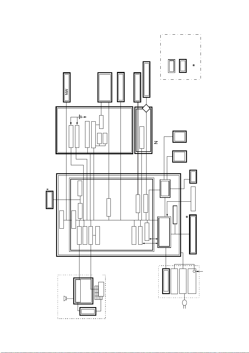
1. Connect the cables ..........................................................................................D-1
2. Disassembly/REassembly ...............................................................................D-2
2-1. FAX1 Board .............................................................................................D-2
2-2. NCU Board ..............................................................................................D-4
2-3. Optional Memory Board ...........................................................................D-5
2-4. TX (Transmission) marker .......................................................................D-6
2-5. Battery Replacement ...............................................................................D-8
2-6. Adjustment for FAX ..................................................................................D-8
(1) Zoom Adjust for FD and CD (FAX) ..................................................D-8
SOFT SWITCHES, SERVICE MODE
1. CONTROL PANEL KEYS AND TOUCH PANEL .............................................S-1
1-1. Control Panel Keys ..................................................................................S-1
1-2. Jumper switch on NCU board ..................................................................S-2
1-3. Explanation of the Touch Panel ...............................................................S-3
(1) FAX Screen .....................................................................................S-3
(2) Auto-mode Screen ...........................................................................S-3
2. UTILITY MODE ................................................................................................S-4
2-1. Utility Mode selection Screen ..................................................................S-4
2-2. Utility Mode Function Tree .......................................................................S-5
2-3. Settings in the Utility Mode ......................................................................S-6
(1) User’s Choice Mode ........................................................................S-6
(2) FAX Input .........................................................................................S-7
(3) User Management ...........................................................................S-7
(4) Input Accounts .................................................................................S-8
(5) Report .............................................................................................S-15
3. TECH. REP. MODE .........................................................................................S-16
3-1. Tech. Rep. Mode Menu Screen ...............................................................S-16
3-2. Tech. Rep. Mode Function Setting Procedure .........................................S-16
3-3. Tech. Rep. Mode Menu Function Tree ....................................................S-17
(1) Tech. Rep.choice .............................................................................S-18
(2) Counter ............................................................................................S-18
(3) Function ...........................................................................................S-19
(4) System Input ....................................................................................S-19
(5) Fax Set ............................................................................................S-20
4. Maintenance Mode ..........................................................................................S-22
4-1. Maintenance Mode Menu Screen ............................................................S-22
4-2. Maintenance Mode Function Setting Procedure ......................................S-22
4-3. Settings in the Maintenance Mode ..........................................................S-23
(1) Maintenance Mode ..........................................................................S-23
(2) Report .............................................................................................S-24
5. ADJUST MODE ...............................................................................................S-25
5-1. Adjust Mode Menu Screen ......................................................................S-25
5-2. Adjust Mode Setting Procedure ...............................................................S-25
5-3. Adjust Mode Function Tree ......................................................................S-25

FrameMaker Ver.5.5E(PC) FAX for Di251f/Di351f
01.03.22
iii
5-4. Settings in the Adjust Mode .....................................................................S-26
(1) IR .............................................................................................S-26
6. INITIAL MODE .................................................................................................S-27
6-1. Initial Mode Menu Screen ........................................................................S-27
6-2. Initial Mode Setting Procedure .................................................................S-27
6-3. Settings in the Initial Mode .......................................................................S-27
7. SOFT SWITCH LIST .......................................................................................S-28
7-1. List of Defaults .........................................................................................S-28
7-2. List of Soft Switches ................................................................................S-33
TROUBLESHOOTING
1. troubleshooting ................................................................................................T-1
1-1. Diagnosis by Alarm Code ........................................................................T-1
1-2. Communication Error Codes ...................................................................T-2
(1) Errors in operations .........................................................................T-2
(2) Terminal alarm .................................................................................T-3
(3) Communication errors (TX) .............................................................T-4
(4) Communication errors (RX) .............................................................T-6
(5) Malfunction ......................................................................................T-8
1-3. Diagnosis by Symptoms ..........................................................................T-9
2. Warm Restart ...................................................................................................T-18
2-1. Overview ..................................................................................................T-18
2-2. How to Operate Warm Restart ................................................................T-18
2-3. Warm Restart Steps ................................................................................T-18
3. Clearing RAM Unconditionally .........................................................................T-19
3-1. Overview ..................................................................................................T-19
3-2. Operation of Unconditional RAM Clear ....................................................T-19
3-3. Steps of Unconditional RAM Clear ..........................................................T-19

FrameMaker Ver.5.5E(PC) FAX for Di251f/Di351f
01.03.22
GENERAL,
MECHANICAL/ELECTRICAL

FrameMaker Ver.5.5E(PC) FAX for Di251f/Di351f
01.03.22
M-1
1. SPECIFICATIONS
1-1. List of Specifications
*: TX marker is unavailable for 2 sided document feeder (ADFR).
Specifications
Memory Capacity 32 MB
Communication mode ECM / G3
Scanning resolution
(main line x feed line) 8 x 3.85 line/mm, 8 x 7.7 line/mm, 8 x 15.4 line/mm,
16 x 15.4 line/mm
Data speed G3 / ECM: 33.6 Kbps - 2.4 Kbps
Transmission time G3 / ECM: Image signal - Pass the 2 sec (V.34 JBIG)
Coding method MH / MR / MMR / JBIG
Applicable network G3 / ECM: Phone line
Options Optional memory board
TX marker *

FrameMaker Ver.5.5E(PC) FAX for Di251f/Di351f
01.03.22
M-2
1-2. List of Functions
Function ( : available : unavailable)
Speed High speed scanning (0.55 sec./Letter Crosswise fine)
High speed printout (35 CPM: 35 ppm/Letter Crosswise)
(25 CPM: 25 ppm/Letter Crosswise)
ECM mode (Pass the 2 sec. /Std. document)
High speed half tone
Resolution Super fine mode
Half tone transmission
Auto retransmission after
error (ECM)
Full automatic exposure
control (Copy/FAX)
Smoothing (FAX function)
Mixed mode (Text + Photo)
Operability One-touch dialing (300 destinations)
# of abbreviated dialing number
Abbreviated dialing (500 destinations)
One-touch program dialing (30 destinations)
# of one-touch dialing number
Auto re-dialing
Destination retrieval
Utility
functions 2-in-1 printout
2-to-1 page transmission
TX marker (option)
FAX/Phone automatic
switch (Ringer count method)
Password communication
Multi polling
Polling at regular times
Non storage transmission
Priority transmission
Insert destination
Automatic pause for PSTN
number
Power Source saving mode (ENERGY STAR )
Switch document reading
length (1 m / 4 m)
R

FrameMaker Ver.5.5E(PC) FAX for Di251f/Di351f
01.03.22
M-3
Function ( : available : unavailable)
Report
functions Activity report (TX/RX)
Transmission report (with document margins, Result report)
Uncompleted transmission
report (with document margins, Result report)
Serial broadcast report (with document margins, Result report)
Relay report (with document margins)
User account report
Abbr. dial# list
One-touch dial# list
Fax program list
Relay group list
Memory
functions Retransmission (destination changeable)
Document retransmission
Reception by memory
Transmission post (30 destinations)
Memory polling transmis-
sion
confidential transmission
confidential print (F code)
Serial broadcast (210 destinations)
Relay broadcast (F code)
Memory full control (Separate Tx)
Quick memory transmis-
sion
File backup
Rotated Rx
Selective polling
System
Configuration Relay transmission
Extra telephone (PB forwarding receivable,
PSTN - port 1 only)
Management function per
business section (100 sections, User management)
Chain dialing
Inch/mm conversion
PC print (Option)
Maintenance Self diagnostics (Memory dump/display, protocol trace,
S/W switch list, service call setup
Counter per application
Adjust touch panel registra-
tion.
Adjust ADF zoom ratio
(main/sub) (FAX independently)
Adjust BS zoom ratio
(main/sub) (FAX independently)

FrameMaker Ver.5.5E(PC) FAX for Di251f/Di351f
01.03.22
M-4
2. CIRCUITRY OPERATION
OPE CPU
INV
Control Panel
Speaker
OPE Unit
LCD
PPC
Copier engine
Power unit
Paper cassette
Copier Unit
No paper LED
KEY Touch
Panel
Legend
LSI
Board
Option
CPU
IPUS R4K I/F
SCU1
SCU2
LCDC
VRAM
Centro1
PCI
CODEC3
CODEC2
NCU I/F
MEMC
MFB2
DRAM
RTC
BBRAM
Universal Port
MDM
FONT-ROM
AFE
ROM
RAM
FPLAN
CCD
BCR
ACR
FCUE
DRAM
ROT8,16,TMEM Ni-MH battery
Extended Memory
Li
DG
*
*
NWROM2
NCU1
COD
CODEC1
ESP2
Centronics
connector
FAX1
NWM
*
CEN
Controller Board
4015M518CA

FrameMaker Ver.5.5E(PC) FAX for Di251f/Di351f
01.03.22
M-5
3. FUNCTION OF CIRCUIT BOARD
Name Description
MFB2
This board is a micro program control circuit that forms the nucleus of the
external 32 bit RISC processorpossessing software circuit controls, read-
ing station controls, recording controls, structural controls, operating con-
trols, reading controls, CCD driver circuit, CCD output image process
circuit, binary image process circuit, motor controls circuit and sensor I/F
circuit.
FAX1
This board performs V.34 facsimile communications, loaded with a V.34
modem.
It also possesses clock IC circuit, SRAM circuit for storing different types
of registration information, battery back-up circuit for file memory, pro-
gram ROM (mask ROM: 16MB) and various types of communication sys-
tem options.
CEN PC printer functions are achieved via connection of this PKG to the MFB2
board.
It also possesses a I/F for network LAN board (FPLAN) use.
NWROM2 This board has 12 or 16MB capacity used as a program ROM.
EMU This board has 12MB capacity used as working memory.
NWM This board has 32MB capacity used as working memory.
Excluded from specifications with EMU.
NCU This board is a line controller to detect line signals such as line connec-
tion and ringer.
FPLAN A network function is achieved via connection of this board to a CEN
board.

FrameMaker Ver.5.5E(PC) FAX for Di251f/Di351f
01.03.22
M-6
3-1. MFB2 Board
•The MFB board is a main controller that has an external 32 (internal 64) bit RISC proces-
sor. It controls several units of the system (e.g., circuitry of each unit, transmitter, reader,
printer, mechanically moving parts, and operation) according to system software.
The MFB2 board has 4 main blocks:
(1) Main Controller
1. Overview
•CPU and an IPUS LSI for controlling several blocks and work memory (DRAM).
•The main controller also uses the information of the backup memory (SRAM) mounted
on FAX1 (ROM/RAM) board for various controls.
✽Block diagram
IPUS LSI
CPU
AD bus
Address bus
Address bus
Clock Various
I/Os
Control
panel
LCD
DRAM
SRAM
ROM data bus
Data bus
ROM
Back up battery
MFB2
FAX1
4015M502CA

FrameMaker Ver.5.5E(PC) FAX for Di251f/Di351f
01.03.22
M-7
2. Function
•CPU
It uses an external 32 bit RISC processor.
•IPUS LSI
It connects the CPU and the controller for controlling overall operation of the system.
•Program memory (ROM)
The software program for operating the system is stored here.
It has a memory capacity of 16 MB.
•Work memory (DRAM)
This memory serves the work area of the system operation.
Standard memory capacity is 4 MB on the MFB2 board.
•Backup memory (SRAM)
It is a 512KB memory that stores the status information of the system.
3. Backup function
•Method
*: Daily usage 12 hours - It will last at least 10 years even if the system is always ON.
4. Backup contents
Backup location Method Lifetime Voltage/current
Battery backup RAM Lithium battery 5 years approx 3 V / 1000 mAh
Clock LSI (discharge type) *
Back up location Contents
Battery Backup
RAM
•Phone number........ Abbreviated phone numbers
•Self-data................TSI information and serial number are backed up
•Soft switch..............Registration data of soft switches
•Communication management....Information on activity reports
Clock LSI Time count

FrameMaker Ver.5.5E(PC) FAX for Di251f/Di351f
01.03.22
M-8
(2) Image Data Processor/FAX Communicator
1. Overview
•This processor has interface blocks with the scanner unitor the printer units, and the FAX
communication block.
•It has the storage coder/decoder and a storage code memory manager (FCUE,LSI),
image memory (DRAM FILE), a printer controller (FCUE LSI), a modem (V.34), and a
communication controller (built in FCUE LSI).
•Each block is controlled by the CPU of the MFB2 board.
•The image memory has an external battery for backup.
✽Block diagram
2. Function
A. Storage coder/decoder (FCUE LSI)
•The coder function codes image data into stored code data. The decoder function
decodes stored code data into image data.
B. Image memory manager (FCUE LSI)
•This block reads/writes the stored code data through interface units (the scanner, the
printer, and the communication units) from/into DRAM FILE by the unit of 1 block.
•The maximum data throughput for DRAM FILE is 320 Mbps. A time division method is
used to refresh read/write of the data through the interface units, and DRAM FILE.
FCUE LSI
Storage coder
Storage
decoder
Print
image size
converter
Backup
circuit
FAX1 Board
Storage
coder
Communication coding/decoding
Communication
image size
converter
FAX1 Board
FAX
Control signal
V.34
Modem
Video signal
ESP2 LSI
IPUS
LSI
Printer
Control signal
File management
Image
memory
Storage decoder
4015M503CA

FrameMaker Ver.5.5E(PC) FAX for Di251f/Di351f
01.03.22
M-9
C. Image memory (DRAM FILE)
•Standard system has a TMEM board (32 MB) on the MFB2 board CN5.
•The maximum capacity is 64MB by installing another ROT board and a TMEM board on
the CN6.
D. Printer controller (FCUE LSI)
•It processes the line density conversion for print image data (serial data) from the storage
decoder, and stores it in the internal frame memory.
•The converted data is read synchronized with the PPC printer, added information on the
left margin and the white mask, and then output to the printer as serial data.
•The frame memory can hold up to 20 Kbit of data to be output to the printer.
•The printer controller exchanges commands/statuses for controlling the printer unit.
E. Communication controller (FCUE LSI and IPUS LSI)
•This controller performs necessary functions (relay control, ringer detection, line connec-
tion detection, polarity reverse detection, dialing and pulse sending) for G3 communica-
tion.
•It also detects the frequency of the tonal signal of G3 communication.
3-2. FAX1 Board
•This board comes loaded with a G3 modem for communicating V.34 facsimile communi-
cations.
•It also possesses clock IC circuit, SRAM circuit for storing different types of registration
information, battery back-up circuit for file memory, program ROM (mask ROM: 16MB)
and optional I/F for different types of communication systems.
•This item describes functions other than for the FAX1 board described in the MFB2
board.
1. Modem (V.34 modem)
•This modem is configured with a digital signal processor, analog front-end that converts
A/D and D/A, modem F/WROM and Book memory (SRAM).
•It conforms to electrical communications conditions provided in recommended V.8, V.34,
V.17, V.29, V.27ter, V.21ch2, T.3, and T.4. It also follows the T.30binary signal procedure.
The transmission speeds are 33600, 31200, 28800, 26400, 24000, 21600, 19200,
16800, 14400, 12000, 9600, 7200, 4800, 2400, and 300 bps.
•It also transmits PB tones when calling PB. This modem is positioned on the memory
map on the MFB2 board.
2. Communication controller (FCUE LSI and IPUS LSI)
•It achieves relay controls, ringer detection, closed DC line wire connection detection and
dial pulse functions.
•It also detects tonal frequencies in G3 procedures.
3. Image memory backup circuit
•It maintains memory capacity by switching the power supply when the device power is
OFF or during a power failure from the battery for a maximum image memory of 64MB.
Installing board memory capacity
25 / 35 CPM TMEM 32 MB

FrameMaker Ver.5.5E(PC) FAX for Di251f/Di351f
01.03.22
M-10
3-3. CEN Board
1. Overview
•This board is configured with a 36-pin bi-directional centronics interface and a network
LAN board interface with PCI bus for use as PC printer font and PC printer.
✽Block diagram
2. Function
•36-pin centronics interface (universal connector)
The system has the IEEE1284 interface (the Centronics interface) as a standard inter-
face to be used as a PC printer for future expansion.
•PCI bus (special connector)
It achieves network functions through network board (FPLAN) connection. This connec-
tor is not a cartridge-type interface but a dedicated connector (100 pin) for the original
board (FPLAN). Therefore, the market-available PCI bus port cannot be connected.
MFB2
CPU
AD bus
IPUS LSI
140pin connector
CEN
Universal connector conforming
to IEEE1284 interface 36-pin centronics
PCI bus
100-pin dedicated connector
36pin connector
to PC
FPLAN
100pin connector
4015M504CA

FrameMaker Ver.5.5E(PC) FAX for Di251f/Di351f
01.03.22
M-11
3-4. NCU Board
(1) Overview
•The NCU board has various functions such as line connection, ringer detection, off-hook
detection, polarity detection, and dialing pulse transmission.
✽Block diagram
(2) Function of each block
•LINE is a modular port for connecting a phone line.
•TEL is another modular port to connect an extra telephone set.
•The dialing pulse transmitter outputs dial pulses controlled by the MFB2 board.
•The ringer detector provides an automatic reception function. It isolates a receiver ringer
signal with a photo-coupler, and outputs it to the MFB2 board. The ringer signal is
counted by the counter of G/A.
•The polarity detector uses two photo-couplers to detect the DC polarity of the line. If
either of the detected signals is “1”, the other signal is “0”.
•The off-hook detector shares a circuit with the polarity detector, and detects off-hook, i.e.,
direct current.
CN11
TEL
CN12
LINE
CN5
Circuit Circuit
SW

FrameMaker Ver.5.5E(PC) FAX for Di251f/Di351f
01.03.22
M-12
4. COMMUNICATION CONTROL
•Communication control of this system follows ITU-T (previously known as CCITT) recom-
mended T.30 binary procedure (G3/ECM; error collection mode).
•Communication mode will be selected automatically with the type of phone line (PSTN)
and the ID signal from a remote terminal.
4-1. V3.4 Mode Communication Procedure
Pre-control

FrameMaker Ver.5.5E(PC) FAX for Di251f/Di351f
01.03.22
M-13
(1) V3.4 Mode Communication Procedure
V3.4 mode does not always select the transmission speed of 36.6Kbit/s. An optimal trans-
mission speed will be selected according to the sequences described in the item 3 and 4
below in order to establish communication.
•Transmission speed : 36.6 to 2.4 Kbit/s (by 2.4 K step)
•Symbol rate : 6 rates (5 rates are supported)
3429, 3200, 3000, 2800, (2743), 2400 symbol/s
1. CNG
•Calling tone
A monotone signal of 1100 Hz, transmitted with the period of 0.5 sec ON and 3 sec OFF.
2. V.8
•Modem ID sequence
A 300 bit/sec. signal.
•This sequence exchanges information on function types and modulation methods with a
remote terminal. The following sequenceswillbe proceeded with the modulation method
that both terminals have among the exchanged system information.
3. Line probing
•Sequence to measure line characteristics.
•This sequence measures the line characteristics by exchanging signals between two
modems.
The symbol rate will be determined by this sequence. This sequence will be one of basis
for data to determine the transmission sequence.
4. TRN
•Equalizer training sequence
•This sequence correspondsto the conventional procedure TCF. Sending a signal with
the fastest transmission speed specified by the remote terminal sets the equalizer of the
modem of the receiver terminal.
5. Control channel
•Sequence to determine modem parameters and system parameters.
A signal of 1200 bit/sec.
•It corresponds to the conventional procedure of phase B.
A. A sequence for determining modem parameters
•It determines the transmission speed of the primary channel by the results of the line
probing sequence and TRN (equalizer training sequence).
B. Sequence to determine system parameters
•The same sequence as the conventional phase B procedure.
6. Primary channel
•Sequence for transmitting image data.
•It corresponds to the conventional phase C procedure.
7. Control channel
•It corresponds to the conventional phase D procedure. A signal of 1200 bit/s.
A. Sequences between pages when there are multiple pages.
B. Page termination sequence.

FrameMaker Ver.5.5E(PC) FAX for Di251f/Di351f
01.03.22
M-14
4-2. Communication Mode
(1) Priority
•This system has two communication modes: ECM and G3. Communication will be estab-
lished with an appropriate mode determined by the capability of the remote terminal. The
priority of the communication modes is as follows:
Note:
G4/UHS/G2/MF modes are unavailable to the system.
(2) Communication modes of ECM/G3
An optimal mode will be selected according to the capabilities of both terminals:
V.34: 33600 ~ 240 bps starting mode
V.17:14000 bps starting mode
V.29: 9600 bps starting mode
<<2>> Encoding Method
There are 4 encoding methods available to this system: JBIG, MMR, MR, MH. An optimal
method will be selected according to the capabilities and image quality of both terminals.
Note:
UMH/UMR are unavailable to the system.
Priority Communication
mode Remark
1st ECM Followed ITU-T (Previously CCITT) recommendation
(Can communicate with other company’s system).
Error correction by procedure signals.
2nd G3 Followed ITU-T (Previously CCITT) recommendation
(Can communicate with other company’s system)
RX (Receiver)
V.34/ECM V.17/ECM V.17/G3 V.29/ECM V.29/G3
V.34/ECM V.34/ECM V.17/ECM V.17/G3 V.29/ECM V.29/G3
TX V.17/ECM V.17/ECM V.17/ECM V.17/G3 V.29/ECM V.29/G3
(Sender) V.17/G3 V.17/G3 V.17/G3 V.17/G3 V.29/G3 V.29/G3
V.29/ECM V.29/ECM V.29/ECM V.29/G3 V.29/ECM V.29/G3
V.29/G3 V.29/G3 V.29/G3 V.29/G3 V.29/G3 V.29/G3
Encoding method Binary priority Remark
JBIG 1st ECM
MMR 2nd ECM
MR 3rd
MH 4th
This manual suits for next models
1
Table of contents
Other Minolta Fax Machine manuals

Minolta
Minolta FAX5600 User manual

Minolta
Minolta Di181f User manual

Minolta
Minolta Minoltafax 1900 User manual

Minolta
Minolta MF3800 User manual

Minolta
Minolta 5500 User manual

Minolta
Minolta Minoltafax 1300 User manual

Minolta
Minolta MF2600 User manual

Minolta
Minolta MINOLTAFAX 1600e User manual

Minolta
Minolta MINOLTAFAX 1600 User manual