211
CABINET LOCATION: An air space of at least 2” must be maintained on all sides of the freezers. Do not
install this freezer in a warm unventilated room that exceeds 80oF; do not place freezer in direct sun-
light; do not place freezer under or near heat range or heating vent.
CABINET LEVELLING: The freezer has to be completely leveled side to side and front to back or slightly
tilted front to back but never tilted forward. Once the freezer is placed in its final location, use a carpenter
level to level the freezer. Proper leveling of the freezer is important for the door closing.
INSTALLATION INSTRUCTIONS
• DO NOT USE AN EXTENSION CORD
• DO NOT CUT, REMOVE OR BYPASS THE GROUNDING PRONG FROM THE PLUG
• DO NOT PLUG INTO AN OUTLET CONTROLLED BY A WALL SWITCH
• ENSURE POWER CORD IS NOT CUT OR DAMAGED FROM PINCHING, KNOTTING, OR MISHANDLING
NOTICE:
Failure to follow these instructions may void the warranty and/or cause loss of product.
PO ER REQUIREMENTS: The freezer requires a 15 Amp dedicated and properly grounded
115V circuit with a NEMA 5-15P receptacle. Wiring should be sized according to the amperage
rating stated on the serial plate. Failure to use a dedicated circuit may cause the circuit breaker
to trip off and/or cause voltage drops. As a result, power to the freezer may be interrupted
and freezing performance can be adversely affected which may cause equipment damage
and/or product loss.
Voltage supply to the freezer must not vary more than ±10% of the nominal voltage, or performance may be
affected. The warranty does not cover damage resulting from excessive voltage variations.
NEMA 5-15P
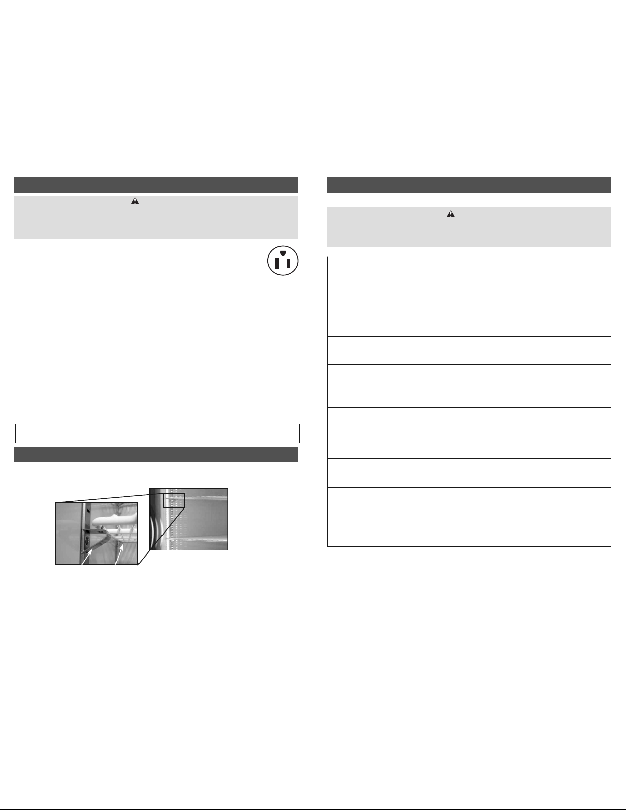
Metallic Clip Shelf
The clips can be removed at any time if a new position is chosen for the shelf or basket. To remove, grab
the clip with your thumb and index finger, then push up the slanted surface until the clip is free. A slight
hit upwards to the slanted surface is usually an easy way to remove the clip. Once the clips are in place,
put the shelf on top. Once the shelves are securely in place, baskets (if equipped) may be positioned on
the shelves.
The freezer is supplied with shelves and metallic clips. The freezer has slotted pilasters to position the
shelves according to the customer’s needs.
SHELF AND BASKET INSTALLATION, ADJUSTMENT
for online reference go to www.minusforty.com
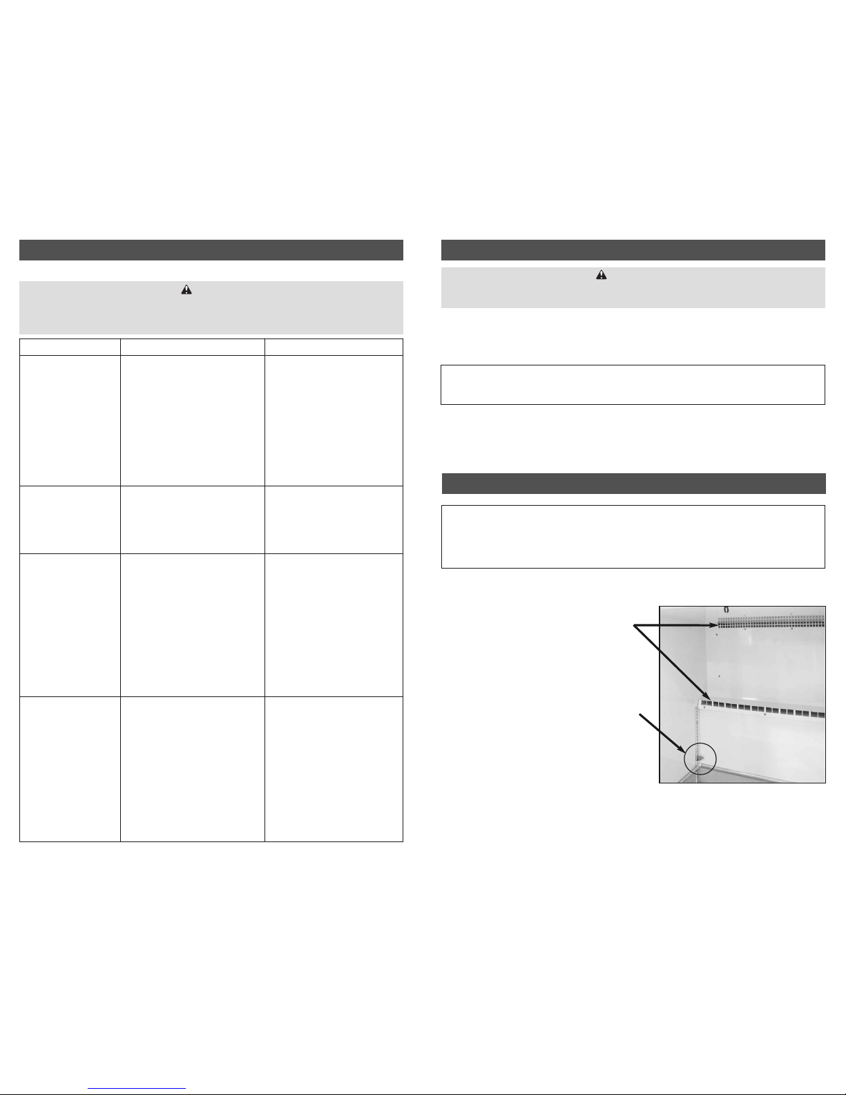
TROUBLESHOOTING GUIDE CONT...
Problem Possible Cause Action
Condensation on glass door. • Door not closing properly.
• Room humidity too high.
• Glass door not heated.
• Check the spring tension or any
obstruction
• To prevent condensation, room
humidity should be below 55%.
• Check heated glass transformer located
behind front bottom grill
LED strips are not working. • Light switch is off.
• Burned out LED strip.
• Check if the light switch is on.
• Replace the LED strip. (See page 9)
Cabinet is noisy. • Part(s) loose
• Tubing vibrating
• Locate and tighten loose part(s).
• Ensure tubing is not in contact with
other tubing or components.
Door does not close tight. • Freezer is not leveled.
• Hinges are loose / not adjusted.
• Gasket is out of the groove.
• Level the unit (See page 2).
• Adjust / tighten the hinge screws.
• Check gasket condition. Adjust position
or replace gasket.
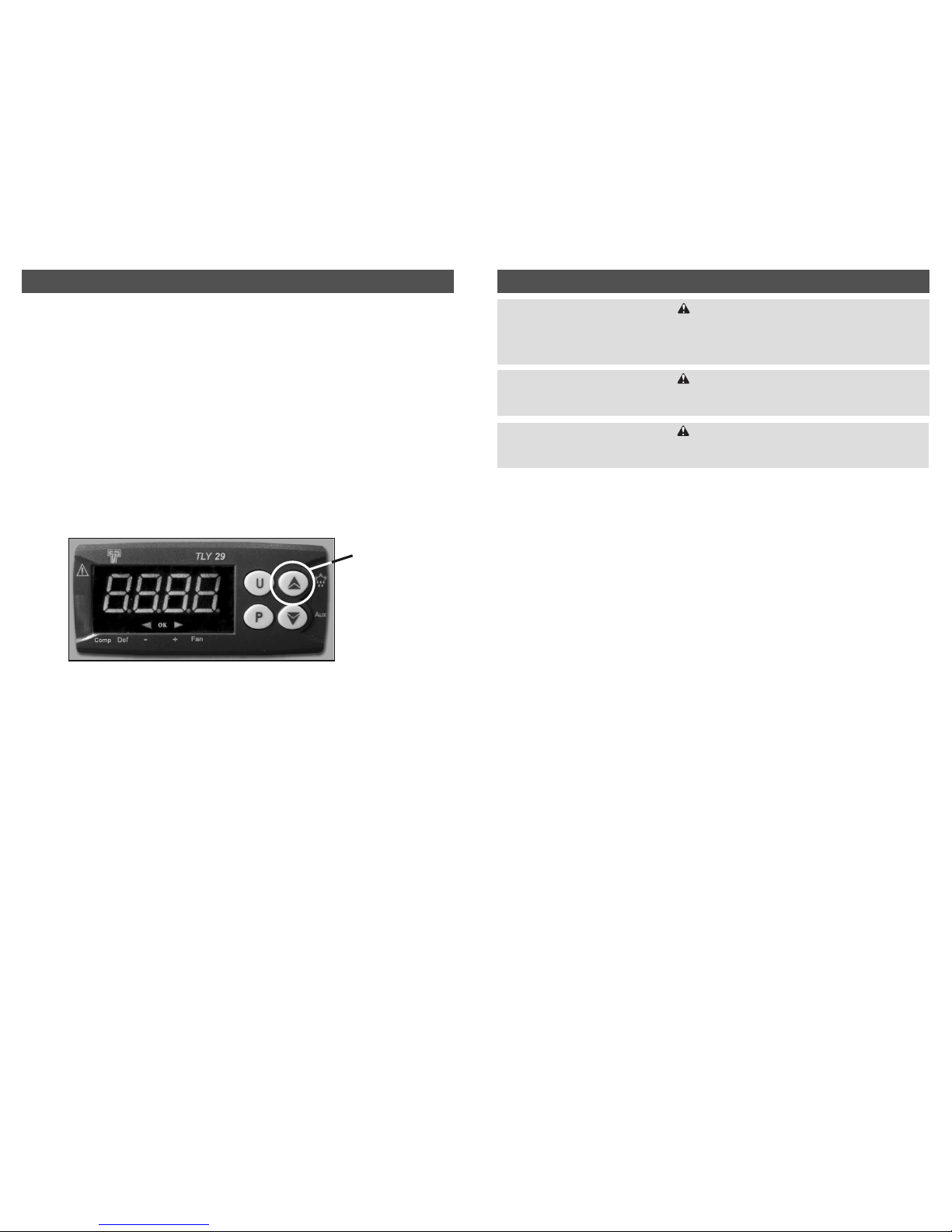
Electronic control blank,
flashing, or displaying incorrect
characters.
• Wires disconnected at back of
electronic control.
• See actions described on the
• controller section. (page 4)
Evaporator fan does not run. • Fan wire disconnected.
• Door switch not working.
• Defrost probe not attached to
the evaporator coil.
• Check wiring.
• Check door switch.
• Check the location of defrost probe.
It should be pressed in between fins in
the middle of the evaporator and close
to the cabinet top
ARNING
Make sure the freezer is disconnected from the power supply before any service. Press the
freezer switch to the “Off” position then unplug the power cord from electrical receptacle.
All service work must be conducted by a certified technician only.
ARNING
This freezer MUST be installed on a dedicated grounded circuit protected with a 15 Amp circuit breaker or
a 15 Amp time delay fuse. Do not remove ground prong. If the cord or plug is damaged, replace with the
same type. Refrigeration and electrical work must be performed by a qualified technician. Failure to follow
these instructions can result in death, fire, or electrical shock.