415
Once the freezer is running, the inside temperature will start to cool down within a couple of minutes.
Ensure that the freezer has reached the desired temperature (this will take between 2 to 3 hours) by
checking the electronic control display readout before loading product. It is strongly recommended to
run the freezer empty for 24 hours before loading any products.
NOTE:
If the freezer is running and the power supply is interrupted, the freezer will not restart
Immediately. There is a 6 minute delay for compressor protection.
OPERATING INSTRUCTIONS
WARNING
Check with your power company if you are not certain of your power supply.
Before connecting to power supply the freezer should be upright and idle for at least 1 hour.
Once the unit has been installed and the power supply has been connected, press
the power switch to the “ON” position using a pen or pencil.
The compressor will start to run after 6 minutes. This can be confirmed by
listening for a slight humming or a slight vibration.
for online reference go to minusforty.com
TROUBLESHOOTING GUIDE
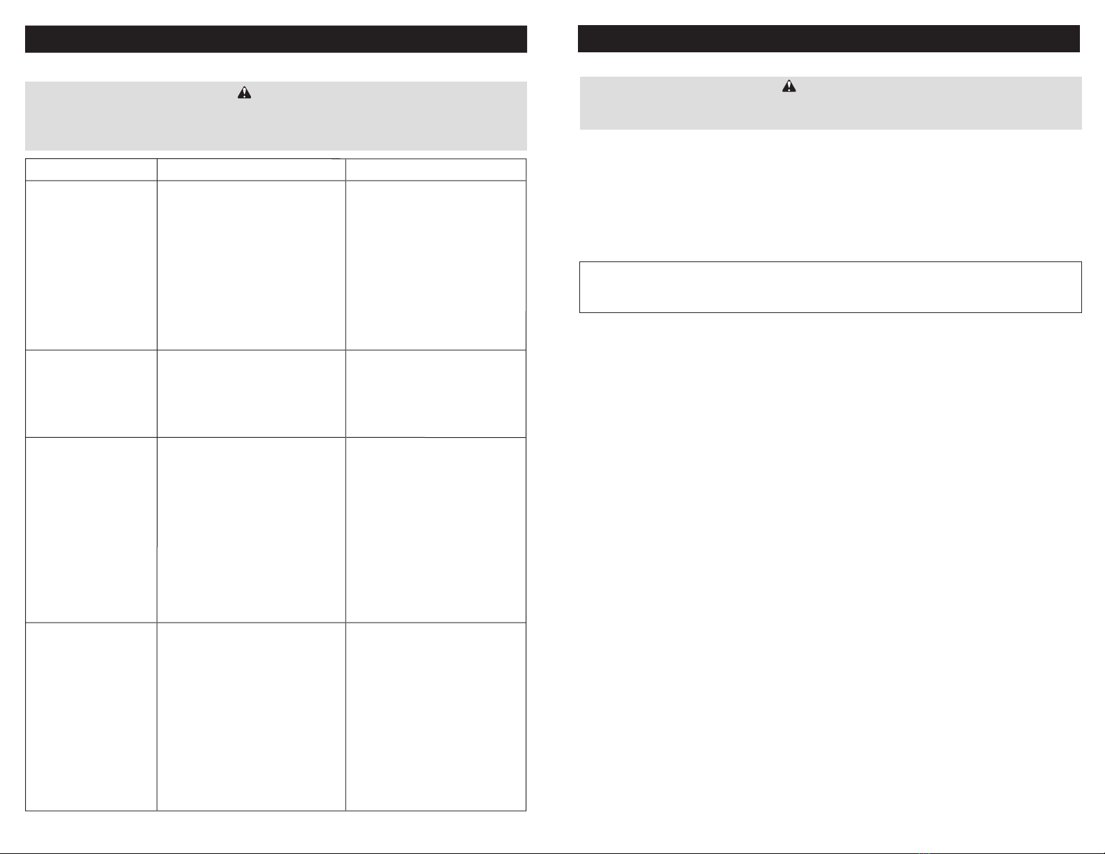
Problem Possible Cause Action
Freezer not operating. • Freezer switch located on the front grill
turned off.
• Fuse blown / circuit breaker tripped.
• Power cord unplugged.
• Receptacle not working.
• Improper voltage supplied to
cabinet / over load circuit.
• Turn power switch on.
• Replace fuse/reset circuit breaker.
• Plug in power cord.
• Check receptacle.
• Remove extension cords or other
equipment on the same circuit.
Freezer not getting cold but
compressor is operating.
• Freezer located in direct sunlight or
ambient (room) temperature is too hot.
• Condenser clogged with dust.
• Move freezer away from direct
sunlight.
• Room temperature is recommended
not to exceed 86ºF (30ºC), 55% RH.
• See page 9 (Cleaning)
Condensing unit operating
for a prolonged period or
continuously.
• Freezer loaded with excessive amount
of warm product.
• Prolonged door opening or door ajar.
• Door not closing properly.
• Clogged condenser.
• Evaporator coil blocked with ice or
frost.
• Allow enough time for product
to cool down.
• Close door when not in use.
Avoid prolonged door openings.
• Level the unit (See page 2).
Check gasket condition.
Check the door spring.
• Clean the condenser (See page 9).
• Defrost manually if required
(See page 8).
Freezer cabinet temperature
too high.
• Electronic control set too high.
• Poor air circulation in cabinet.
• Insufficient clearance around cabinet or
ambient temperature too high.
• Clogged condenser
• Adjust control setting (See page 6).
• Follow instructions for product
loading (See page 5)
• Keep at least 6”(15.24cm) free space
around all sides of the freezer. Room
temperature is recommended not to
exceed 86ºF (30ºC), 55% RH.
Make sure the air flow to the
compressor is not obstructed.
• Clean the condenser (See page 9)
WARNING
Make sure the freezer is disconnected from the power supply before any service. Press the
freezer switch to the “Off” position then unplug the power cord from electrical receptacle.
All service work must be conducted by a certified technician only.