Minusforty 09-USGF User manual

MNL_R290_USGF-UDGF_EN180312
Model:
Serial Number:
Date of Purchase:
30 Armstrong Avenue
Georgetown, Ontario
Canada L7G 4R9
Tel: 800.800.5706 or 905.702.1441
Fax: 905.702.1442
Email: info@minusforty.com
Web: www.minusforty.com
To better help you obtain assistance or service should you ever need it, write down the
following information about the product. This information is on the identification label
located on the left hand inside wall of the cabinet. We advise you to keep this Owners
Manual and sales slip in your possession.
Owners Manual
Glass Door Freezers
You know it’s cold when it’s Minus Forty®
TEL 8 .8 .57 6 • 9 5.7 2.1441 • FAX 9 5.7 2.1442 • WWW.MINUSFORTY.COM
3 ARMSTRONG AV E . GEORGETOWN, ONTARIO CA N A D A L7G 4R9
Single and Double Door Models
09-USGF, 09M-USGF, 09X-USGF
10-USGF, 10M-USGF, 10X-USGF
13-USGF, 15-UDGF, 19-USGF
22-USGF, 43-UDGF, 44-UDGF


WARNING
THIS UNIT IS CHARGED WITH PROPANE REFRIGERANT.
PROPANE IS AN EXTREMELY FLAMMABLE AND EXPLOSIVE
GAS. PLEASE READ CAREFULLY THIS MANUAL/GUIDE AND
FOLLOW ALL SAFETY PRECAUTIONS CONTAINED HEREIN TO
REDUCE A RISK OF FIRE AND/OR EXPLOSION. FAILURE TO
FOLLOW THE SAFETY PRECAUTIONS MAY RESULT IN
SERIOUS INJURY OR DEATH, AND/OR PROPERTY DAMAGE.
CAUTIONAR INSTRUCTIONS FOR UNITS CHARGED WITH
PROPANE (R290) REFRIGERANT
• DANGER - RISK OF FIRE OR EXPLOSION. FLAMMABLE REFRIGERANT USED.
DO NOT USE MECHANICAL DEVICES TO DEFROST REFRIGERATOR. DO NOT
PUNCTURE REFRIGERANT TUBING.
• DANGER - RISK OF FIRE OR EXPLOSION. FLAMMABLE REFRIGERANT USED.
TO BE REPAIRED ONL B FACTOR AUTHORIZED TRAINED SERVICE
PERSONNEL. DO NOT PUNCTURE REFRIGERANT TUBING.
• CAUTION - RISK OF FIRE OR EXPLOSION. FLAMMABLE REFRIGERANT USED.
CONSULT REPAIR MANUAL/OWNER'S GUIDE BEFORE ATTEMPTING TO
SERVICE THIS PRODUCT. ALL SAFET PRECAUTIONS MUST BE FOLLOWED.
• CAUTION - RISK OF FIRE OR EXPLOSION. DISPOSE OF PROPERL IN
ACCORDANCE WITH FEDERAL OR LOCAL REGULATIONS.
FLAMMABLE REFRIGERANT USED.
• CAUTION - RISK OF FIRE OR EXPLOSION DUE TO PUNCTURE OF REFRIGER-
ANT TUBING; FOLLOW HANDLING INSTRUCTIONS CAREFULL . FLAMMABLE
REFRIGERANT USED.
Propane is approved for use as a refrigerant in commercial, self-contained units in Canada
and USA under limited use conditions. It can e used in new equipment only, retrofitting is
not allowed, with a limited charge of up to 150 grams (5.3 oz) per refrigeration circuit. Even
though this is a small amount, it still presents a fire/explosion hazard if it leaks out of refrig-
erant containing parts. When mixed with air, a flamma le propane-air mixture can e created
and easily ignited y sparks, open flames, or hot surfaces. This is particularly true in confined
zones. Propane is heavier than air and tends to settle at lower points.
To mitigate the risk, please follow the precautionary measures as follows:
• Avoid unit installation in areas with open flames (kitchens, repair garages or the like), or
in vicinity of open flames or high surface temperatures.
• Avoid unit installation in confined spaces. Well ventilated areas are preferred. Keep clear
all ventilation openings of o structions.
• Do not rely on smell to detect potential leaks of propane refrigerant. Propane refrigerant is
a high purity propane gas and does not contain any stenching agent(s). Stenching agents
are typically used in fuel-grade propane and natural gas to detect their presence in air y
relying on smell.
• All repairs must e performed in well ventilated areas.
• To minimize the risk of possi le ignition due to incorrect parts or improper service, compo-
nent parts shall e replaced with like components and servicing shall e done y service
personnel authorized y Minus Forty Technologies Corp.
• Do not attempt to modify the unit or remove any functional part(s) from the unit.
• Handle the unit with care to avoid any damage.
• When transporting the unit, all appropriate safety considerations must e considered.
Check with local Department of Transportation for detailed requirements pertaining to
transportation of flamma le gasses.
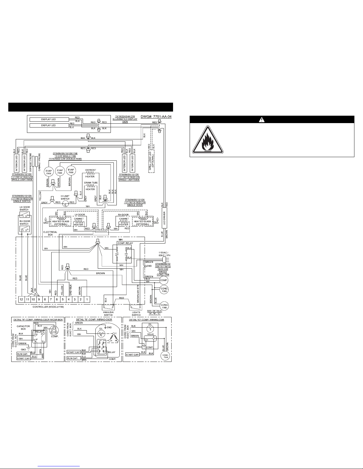
WIRING DIAGRAM (MODELS WITH CONTINUOUS RUN CONDENSER FAN)
24

23
WIRING DIAGRAM (STANDARD MODELS)

22
WARNING
MA E SURE THE FREEZER IS DISCONNECTED FROM THE POWER
SUPPLY BEFORE ANY SERVICE. PRESS THE FREEZER SWITCH TO
THE “OFF” POSITION THEN UNPLUG THE POWER CORD FROM THE
ELECTRICAL RECEPTACLE.
ALL SERVICE WOR MUST BE PERFORMED BY CERTIFIED, FAC-
TORY AUTHORIZED SERVICE PERSONNEL ONLY. COMPONENT
PARTS MUST BE REPLACED WITH LI E COMPONENTS.
COMMERCIAL USE ONLY. NOT FOR HOUSEHOLD USE.
FOR INDOOR USE ONLY.
SAFETY PRECAUTIONS
READ ALL INSTRUCTIONS AND SAVE THESE INSTRUCTIONS FOR
FUTURE REFERENCE.
DO NOT STORE OR USE GASOLINE OR OTHER FLAMMABLE VA-
PORS AND LIQUIDS NEAR THIS OR ANY OTHER APPLIANCE.
DO NOT TOUCH COLD SURFACES WITH DAMP OR WET HANDS.
S IN MAY STIC TO EXTREMELY COLD SURFACES.
DO NOT ALLOW CHILDREN TO CLIMB, HANG OR STAND ON
FREEZER SHELVES.
EEP FINGERS OUT OF PINCH-POINT AREAS.
DISCONNECT POWER TO THE UNIT PRIOR TO CLEANING OR
REPAIRING.
BEFORE DISCARDING THIS OR ANY OTHER APPLIANCE, REMOVE
THE DOORS OR LIDS TO REDUCE RIS OF CHILD ENTRAPMENT.
WHEN RECYCLING THE UNIT, REFRIGERANTS MUST BE HANDLED
IN ACCORDANCE WITH LOCAL AND NATIONAL REGULATIONS.
NOTICE
OPERATING THE FREEZER FOR 24 HOURS PRIOR TO LOADING
PRODUCT IS RECOMMENDED
MONITOR FREEZER TEMPERATURE REGULARLY
ILLUSTRATION: 43-UDGF, 44-UDGF

21
CONTENTS
Warranty
Installation Instructions
Power Requirements
Shelf and Basket, Placement and Adjustment
Operating Instructions
Product Loading
Temperature Adjustment and Switch Functions
Controller Alarms and Signals
Controller Symbols and Functions
Manual Defrost
How to Remove the Front Bottom Grill
Condenser Cleaning
Cabinet Cleaning
ISD Trans-Light LED Strip Replacement
Trans-Light Graphic Panel Replacement
Interior LED Strip Replacement
Troubleshooting Guide
Parts List (09/09M/09X/10-USGF)
Illustration (09/09M/09X/10-USGF)
Parts List (13/19/22-USGF)
Illustration (13/19/22-USGF)
Parts List (15-UDGF)
Illustration (15-UDGF)
Parts List (43/44-UDGF)
Illustration (43/44-UDGF)
Wiring Diagram (Standard Models)
Wiring Diagram (Continuous Run Condenser Fan Models)
1
2
2
3
3
4
5
5 - 6
6
7
7
8
8 - 9
10 - 11
11
12
13 - 14
15
16
17
18
19
20
21
22
23
24
PARTS LIST: 43-UDGF, 44-UDGF
No Description
1 LED Strip
2 LED Driver
3 Pressure Relief Ball
4 Pilaster
5 Top Display Assembly
6 Basket
7 Pilaster Clip
8 Shelf
9 Interior Back Grill
10 Bottom Shelf
11 Rear Grill
12 Front Bottom Grill
13 Door Top Bracket (Left)
14 Door Top Bracket (Right)
15 Heater Breaker Seal LED
16 Torsion Pin
17 Bushing, Nylon (c/w Door)
18 Torsion Bar (c/w Door)
19 Door Assembly (Left)
20 Door Assembly (Right)
21 Door Bottom Bracket (Left)
22 Door Bottom Bracket (Right)
23 Nylon Washer
24 Door Handle
25 Door Switch
26 Cabinet Anti-Condensate Heater
27 Heater Breaker Seal (Bottom/Top)
28 Discharge Header
29 Leveling Leg
30 Caster
31 Evaporator Coil
32 Not Used
33 Defrost Heater
34 Evaporator Tray
35 Evaporator Styroform Pad
36 Drain Tube Heater
37 Evaporator Shroud
38 Evaporator Fan
39 Relay Potential
40 Run Capacitor
No Description
41 Start Capacitor
42 Fan Blade(Condensing Unit)
43 Fan Motor(Condensing Unit)
44 Compressor
45 Heater Breaker Door
46 Filter Drier
47 Condensate Tray
48 Condenser Coil
49 Rocker Switch
50 Controller
51 Compressor Relay
52 Compressor Contactor
53 Defrost Heater/Evaporator Fan Wires
54 Compressor Discharge Line
55 Power Cord
56 Liquid Header
57 Compressor Harness
58 3 Pole Terminal Block
59 5 Pole Terminal Block

20
STANDARD WARRANTY FOR MINUS FORTY®
REFRIGERATION E UIPMENT AND ACCESSORIES
LIMITED WARRANTY
Minus Forty®Technologies Corp. warrants its products to be free from defect as
to workmanship and materials for a period of twelve (12) months from the time
of delivery.
Minus Forty®Technologies Corp. will at its option either replace or repair any de-
fective parts returned within twelve (12) months of the time of delivery, trans-
portation charges prepaid, which Minus Forty®Technologies Corp. in its sole
discretion, determines to be defective.
This warranty shall not apply to any products that have been repaired or altered
outside of Minus Forty®Technologies Corp.’s factory or repair facilities if the re-
pairs in the judgement of Minus Forty®Technologies Corp. have affected the reli-
ability or wear of the product and nor does the guarantee apply to any product
which has been subject to misuse, accident or to any product which has not been
maintained pursuant to the instruction of Minus Forty®Technologies Corp.
This warranty does not extend to any consequential damage caused by the failure
of the product under any circumstance and further, Minus Forty®Technologies
Corp. shall not be responsible for damage to the contents of the product or any
economic loss caused by the failure of the product, whether such loss is suffered
by the customer or a third party user of the product or whether the contents are
owned by the customer or a third party user or supplier.
Effective January 1, 1996
1
ILLUSTRATION: 15-UDGF
MOLDED GRILL STEEL GRILL

19
CABINET LOCATION: An air space of at least 6” (15.24cm) must be maintained on all sides of the
freezer. Do not locate the freezer in a warm unventilated room exceeding 86ºF (30ºC) and 55%RH; do
not place freezer in direct sunlight; do not place freezer under or near heat range or heating vent.
CABINET LEVELING: The freezer must be completely leveled side to side and front to back or slightly
tilted front to back but never tilted forward. Once the freezer is placed in its final location, use a car-
penter level to level the freezer. Proper leveling of the freezer is important for the door closing and
water drainage during the defrost cycle. There are two leg levelers in the front that can be adjusted. First,
loosen the nuts using an adjustable wrench. Second, turn levelers counter-clockwise to raise the freezer,
or clockwise to lower, until they reach the leveled position. Lastly, tighten the nuts again to lock the legs.
INSTALLATION INSTRUCTIONS
• DO NOT USE AN EXTENSION CORD
• DO NOT CUT, REMOVE OR BYPASS THE GROUNDING PRONG FROM THE PLUG
• DO NOT PLUG FREEZER INTO AN OUTLET CONTROLLED BY A WALL SWITCH
• ENSURE POWER CORD IS NOT CUT OR DAMAGED FROM PINCHING, KNOTTING, OR MISHANDLING
NOTICE:
Failure to follow these instructions may void the warranty and/or cause loss of product.
All models require a 15 Amp dedicated and properly grounded 115V/60Hz/1Ph circuit
with a NEMA 5-15P receptacle. Wiring should be sized according to the amperage
rating stated on the serial plate. Failure to use a dedicated circuit may cause the circuit
breaker to trip off and/or cause voltage drops. As a result, power to the freezer may be
interrupted and freezing performance can be adversely affected which may cause equip-
ment damage and/or product loss.
Voltage supply to the freezer must not vary more than ±10% of the nominal 115V, or performance may
be affected. The warranty and liability does not cover damage resulting from excessive voltage
variations.
The anti-fog glass door has a protective film on the inner side. After the
unit has been installed, peel and remove the protective film covering
the inner glass surface.
WARNING
These freezers MUST be installed on a dedicated grounded circuit protected with a 15 Amp circuit breaker
or a 15 Amp time delay fuse. Do not remove ground prong. If the cord or plug is damaged, replace with the
same type. Refrigeration and electrical work must be performed by a qualified technician. Failure to follow
these instructions can result in death, fire, or electrical shock.
2
NEMA 5-15P
POWER RE UIREMENTS:
PARTS LIST: 15-UDGF
No Description
1 Door (Right or Left Hand)
2 Door Top Bracket (Right or Left)
3 Door Bottom Bracket (Right or Left)
4 Torsion Bar
5 Tension Pin
6 Bushing
7 Nylon Washer
8 Door Handle
9 Door Switch
10 Basket
11 Shelf
12 Interior Back Grill
13 Bottom Shelf
14 Pilaster
15 Pilaster Clip
16 Rear Grill
17 Leveling Leg
18 Caster
19 Front Bottom Grill
20 Evaporator Coil
21 Defrost Heater
22 not used
23 Drain Tube Heater
24 Evaporator Tray
25 Evaporator Shroud
26 Evaporator Fan
27 Evaporator Styrofoam Pad
28 Cabinet Anti-Condensate Heater
29 Heater Breaker Seal (Side and Bottom/Top)
30 Heater Breaker Seal (LED)
31 LED STRIP
32 LED Driver (Interior Light)
33 3 Pole Terminal block
34 Controller
35 Rocker Switch
36 Compressor Relay
No Description
37 Power Cord
38 Condensate Tray Assembly
39 Compressor
40 Filter Drier
41 Condenser Coil
42 Heater Breaker Door
43 not used
44 not used
45 Start Relay
46 Start Capacitor
47 not used
48 Overload protector
49 Fan Blade (Condensing Unit)
50 Fan Motor (Condensing Unit)
51 Thermostat, Defrost Limit
PROTECTIVE DOOR FILM

18
Once the freezer is running, the inside temperature will start to cool down within a couple of minutes.
Ensure that the freezer has reached the desired temperature (this will take between 2 to 3 hours) by
checking the electronic control display readout before loading product. It is strongly recommended to
run the freezer empty for 24 hours before loading any products.
NOTE:
If the freezer is running and the power supply is interrupted, the freezer will not restart
Immediately. There is a 6 minute delay for compressor protection.
OPERATING INSTRUCTIONS
WARNING
Check with your power company if you are not certain of your power supply.
Before connecting to power supply the freezer should be upright and idle for at least 1 hour.
3
ILLUSTRATION: 13-USGF, 19-USGF, 22-USGF SHELF AND BASKET, INSTALLATION AND ADJUSTMENT
The freezer is supplied with shelves and molded or metallic clips. The freezer has slotted pilasters to po-
sition the shelves according to the customer’s needs.
Metallic Clip ShelfShelfMolded Clip
The clips can be removed at any time if a new position is chosen for the shelf or basket. To remove, grab
the clip with your thumb and index finger, then push up the bottom surface until the clip is free. Once
the clips are in place, put the shelf on top. Once the shelves are securely in place, baskets (if equipped)
may be positioned on the shelves.
Once the unit has been installed and the power supply has been connected, press
the power switch to the “ON” position using a pen or pencil.
The compressor will start to run after 6 minutes. This can be confirmed by lis-
tening for a slight humming or a slight vibration.

17
NOTICE:
Ensure the freezer has reached the proper operating temperature before loading product.
The electronic control displays the interior cabinet temperature.
Product loss is not covered under warranty.
DO leave at least 6” (15.24cm) free space between
the fan and the product for air circulation.
DO NOT stock any products against the
evaporator fan. See load limit labels inside
the cabinet for reference.
DO NOT block the air space behind the grill.
Free space is required for proper air circulation.
AVOID removing the bottom shelf from the inner
bottom.
DO NOT overstock the unit.
PRODUCT LOADING
For enhanced performance of the unit and to avoid spoilage
of perishable products, follow these instructions:
4
PARTS LIST: 13-USGF, 19-USGF, 22-USGF
No Description
1 Display LED Strip
2 Top Display Assembly
3 Door Switch
4 Heater Breaker Seal (Bottom/Top)
5 LED Driver
6 Pilaster
7 Basket
8 Door Assembly (Right or Left Hand)
9 Pilaster Clip
10 Shelf
11 Interior Back Grill
12 Bottom Shelf
13 Torsion Pin
14 Rear Grill
15 Door Handle
16 Leveling Leg
17 Caster
18 Front Bottom Grill
19 Door Top Bracket (Right or Left)
20 Bushing, Nylon
21 Door Bottom Bracket (Right or Left)
22 not used
23 Evaporator Coil
24 Evaporator Tray
25 Evaporator Shroud
26 Evaporator Fan
27 Relay Potential (22-USGF)
28 Run Capacitor (22-USGF)
29 Start Capacitor (22-USGF)
30 Start Capacitor (13-USGF)
31 Overload Protector (13-USGF)
32 Start Relay (13-USGF)
33 Fan Blade (Condensing Unit)
34 Fan Motor (Condensing Unit)
35 Compressor
36 Filter Drier
No Description
37 5 Pole Terminal Block
38 Controller
39 Rocker Switch
40 Compressor Relay
41 Power Cord
42 Nylon Washer
43 Torsion Bar
44 Defrost Heater
45 Drain Tube Heater
46 Condenser Coil
47 Condensate Tray Assembly
48 Cabinet Anti-Condensate Heater
49 Pressure Relief Ball
50 Heater Breaker Seal (LED)
51 Cabinet LED Strip
52 Thermostat, Defrost Limit
53 Heater Breaker Door

16 5
The electronic controller can detect and signal several alarm conditions: high/low freezer temperatures,
door open and open or short-circuited temperature probes. If the alarm conditions last longer than pre-
programmed time delays, the controller will turn ON an audio signal (buzzer). Also a LED light located
in the upper left corner of the controller, next to the caution symbol, will glow in case an alarm is active.
Once the alarm conditions have been fixed, the controller will turn off the alarms on its own. Alarms can
be disabled by pressing any controller button, during alarm conditions
CONTROLLER ALARMS AND SIGNALS
Message Cause Action
Prl diSC Cabinet temperature probe open • Check connections
• Replace probe
Prl Short CC Cabinet temperature probe short-circuited
Pr2 diSC Defrost probe open • Check connection
• Replace probe
Pr2 Short CC Defrost probe short-circuited
Int Error Internal memory error • Replace controller
Locate the electronic control on the right of the front bottom grill. The electronic control displays ac-
tual temperature inside the freezer. In addition, the electronic control turns the refrigeration system OFF
when freezer reaches the set temperature, and turns the refrigeration system ON after the freezer
temperature rises by 8˚F or after 7 minutes, whichever lasts longer.
TEMPERATURE ADJUSTMENT AND SWITCH FUNCTIONS
ELECTRONIC CONTROLLER
LIGHTPOWERELECTRONIC CONTROL
To adjust the set temperature, follow these steps:
1. Press and release P button; the set temperature and SP1 are displayed alternatively on the controller
2. Press the UP or DOWN buttons to adjust the set temperature.
3. Press P to store the adjusted value; The electronic control will return to cabinet temperature
display. The U Button on the electronic controller is used for displaying cabinet and defrost
temperatures (PR1 and PR2 parameters)
1. POWER switch turns the refrigeration system (including all electrical parts) ON or OFF.
(use a pen or pencil to press the power switch to the ON or OFF position).
2. LIGHT switch turns the internal and external lights ON or OFF.
There are two switches located on the right hand side of the controller.
Their functions are to manually switch electronic components of the freezer.
ILLUSTRATION: 09/09M/09X-USGF, 10/10M/10X-USGF

15
6
At the left side of the controller display are the following LED indicators:
CONTROLLER ALARMS AND SIGNALS CONT...
CONTROLLER SYMBOLS AND FUNCTIONS
Message Cause Action
StArt dELAy Start up delay in progress • Wait for 6 minutes
Hi °F or Hi °C Maximum temperature alarm • Check door
• See Troubleshooting (page 13)
Lo °F or Lo °C Minimum temperature alarm • Adjust set temperature
door oPEn Door open • Close door
1. Indicates compressor status:
Light on - Compressor cooling on
Light off - Compressor cooling off
Light flashing - Start-up delay in progress
2. Indicates defrost status:
Light on - Defrost in progress
Light flashing - Freezer in dripping mode
3. Indicates fan status:
Light on - Cabinet fan ON
Light off - Cabinet fan OFF
Light flashing - Start-up delay in progress after defrost.
4. Indicates the alarm status:
Light on - Alarm is on
Light off - Alarm is off
Light flashing - Alarm silenced or memorized
2
1
3
4
PARTS LIST: 09/09M/09X-USGF, 10/10M/10X-USGF
No Description
1 Door (Right or Left Hand)
2 Door Top Bracket (Right or Left)
3 Door Bottom Bracket (Right or Left)
4 Torsion Bar
5 Tension Pin
6 Bushing
7 Nylon Washer
8 Door Handle
9 Door Switch
10 Basket
11 Shelf
12 Interior Back Grill
13 Bottom Shelf
14 Pilaster
15 Pilaster Clip
16 Rear Grill
17 Leveling Leg
18 Caster
19 Front Bottom Grill
20 Evaporator Coil
21 Defrost Heater
22 Fan Guard
23 Drain Tube Heater
24 Evaporator Tray
25 Evaporator Shroud
26 Evaporator Fan
27 Pressure Relief Ball
28 Cabinet Anti-Condensate Heater
29 Heater Breaker Seal (Bottom/Top)
30 Heater Breaker Seal (LED)
31 LED STRIP
32 LED Driver (Interior Light)
33 3 Pole Terminal block
34 Controller
35 Rocker Switch
36 Compressor Relay
No Description
37 Power Cord
38 Condensate Tray Assembly
39 Compressor
40 Filter Drier
41 Condenser Coil
42 Start Relay
43 Start Capacitor
44 Run Capacitor
45 Overload Protector
46 Fan Blade (Condensing Unit)
47 Fan Motor (Condensing Unit)
48 Thermostat, Defrost Limit
49 Heater Breaker Door

14 7
This freezer is designed for automatic defrost. Every eight hours the refrigeration system is turned OFF and
the defrost/drain heaters are activated to melt the ice from the evaporator coil and drain pan. If the freezer
is not leveled properly, the water may not drain out of the freezer, it will re-freeze and ice gradually builds
up. Excessive ice buildup reduces cooling performance and may cause the failure of refrigeration system
and product loss. Ice buildup may be noticed through the evaporator fan grill on the coil fins.
To perform a manual defrost, follow these steps:
1. Press the UP arrow button and hold it for 6 seconds.
2. Wait until the electronic control stops defrost (the Def LED dot flashes)
3. If ice is still noticeable on the evaporator, press the freezer switch to the “Off” position then
disconnect the freezer from the power supply.
4. Take down the evaporator shroud and use a hair dryer to quickly melt the ice.
5. Make sure the freezer is leveled side to side, and front to back or slightly tilted front to back.
6. Replace the evaporator shroud.
MANUAL DEFROST
With a screwdriver remove the bottom screws
from the grill.
Grasp the bottom grill
from the sides and slide it up
and towards you to release the hooks.
HOW TO REMOVE THE FRONT BOTTOM GRILL
To replace bottom grill, align hooks of the grill with slots and slide the grill back onto the freezer.
Replace the bottom screws to secure the grill to the cabinet.
With a screwdriver, remove the two screws and
washers from the grill front. Grasp the grill behind
ventilation slots as shown, and pull it towards you
with a tugging motion to disengage it from the
plastic latches.
To replace bottom grill, align strike pins care-
fully with the latches. Push the grill back into the
latches until captive.Replace the screws and
washers to secure the grill to the cabinet.
Steel Grill
for online reference go to www.minusforty.com
TROUBLESHOOTING GUIDE CONT...
Problem Possible Cause Action
Condensation on glass door. • Door not closing properly.
• Room humidity too high.
• Check the spring tension or any
obstruction
• To prevent condensation, room
humidity should be below 55%.
LED strips are not working. • Light switch is off.
• Faulty LED strip.
• Check if the light switch is on.
• Replace the LED strip. (See page 12)
Cabinet is noisy. • Part(s) loose
• Tubing vibrating
• Locate and tighten loose part(s).
• Ensure tubing is not in contact with
other tubing or components.
Door does not close tight. • Freezer is not leveled.
• Hinges are loose / not adjusted.
• Gasket is out of the groove.
• Level the unit (See page 2).
• Adjust / tighten the hinge screws.
• Check gasket condition. Adjust position
or replace gasket.
Electronic control blank,
flashing, or displaying incorrect
characters.
• Wires disconnected at back of
electronic control.
• See actions described in the
controller section. (page 5)
Evaporator fan does not run. • Fan wire disconnected.
• Door switch not working.
• Defrost probe not attached to
the evaporator coil.
• Check wiring.
• Check door switch.
• Check the location of defrost probe.
It should be pressed in between fins in
the middle of the evaporator and close
to the cabinet top
WARNING
Make sure the freezer is disconnected from the power supply before any service. Press the
freezer switch to the “Off” position then unplug the power cord from electrical receptacle.
All service work must be conducted by a certified technician only.
Molded Grill

813
NOTE:
The cleaning of the condenser is a service not covered under the warranty
The freezer is designed for minimal condenser cleaning. With the “lint free” condenser design, most
dust and dirt will pass right through the condenser. To insure the proper operation, we recommend
scheduled check-ups and cleaning every three to four months. This period may be shorter or longer
depending on the location in which the freezer was installed. A dirty condenser can result in a voided
warranty, part failure, product loss, and higher electrical cost. The steps to clean the condenser are as
follows:
CONDENSER CLEANING
1. Remove the front bottom grill (see page 7)
2. Switch off power at freezer switch on control panel.
3. Unplug power cord from electrical receptacle.
4. Brush the dirt, dust and paper off the condenser coil plate, all the way to the fan. Use either a
vacuum or blow with a compressed air supply if available.
5. When finished with cleaning, plug power cord back into receptacle.
6. Switch power back on at switch on control panel.
7. Replace bottom grill (see page 7)
CABINET CLEANING
To clean the exterior whether it has the original finish or a decal package, use only a mild non-abrasive
liquid cleaner, water and a soft cloth. For stainless steel parts, a commercial stainless steel polish and
cleaner can be used. Always apply the cleaner to the soft cloth and then clean the freezer. Never apply
the cleaner directly to the freezer. Excess liquid applied to the surface may seep into the electronic con-
trol and switches which can cause an electrical hazard or a malfunction.
DO NOT USE abrasive or caustic cleaners, scouring pads, solvents or flammable liquids.
CAUTION
Do not apply hot water on cold glass components. Allow glass to warm sufficiently to prevent
shattering.
CAUTION
Do not use ammonia or bleach based cleaners or abrasive type cleaners.
Do not use abrasive cleaning pads.
WARNING
To reduce the risk of fire, electrical shock or personal injury, disconnect the freezer from the power
source before cleaning. Press the freezer switch to the “Off” position, then unplug the power cord
from the receptacle. eep liquids away from electrical and electronic components.
GENERAL
The freezer should be cleaned at regular intervals to meet a good standard of hygiene and
to keep the freezer attractive as an effective point of purchase display.
INTERIOR CLEANING
Use only mild non-abrasive liquid cleaner, water and a soft cloth for the entire freezer
interior. Make sure to wipe off all residue.
for online reference go to www.minusforty.com
TROUBLESHOOTING GUIDE
ProblemPossible CauseAction
Freezer not operating.• Freezer switch located on the front grill
turned off.
• Fuse blown / circuit breaker tripped.
• Power cord unplugged.
• Receptacle not working.
• Improper voltage supplied to
cabinet / over load circuit.
• Turn power switch on.
• Replace fuse/reset circuit breaker.
• Plug in power cord.
• Check receptacle.
• Remove extension cords or other
equipment on the same circuit.
Freezer not getting cold but
compressor is operating.
• Freezer located in direct sunlight or
ambient (room) temperature is too hot.
• Condenser clogged with dust.
• Move freezer away from direct
sunlight.
• Room temperature is recommended
not to exceed 86ºF (30ºC), 55% RH.
• See page 8 (Cleaning)
Condensing unit operating
for a prolonged period or
continuously.
• Freezer loaded with excessive amount
of warm product.
• Prolonged door opening or door ajar.
• Door not closing properly.
• Clogged condenser.
• Evaporator coil blocked with ice or
frost.
• Allow enough time for product
to cool down.
• Close door when not in use.
Avoid prolonged door openings.
• Level the unit (See page 2).
Check gasket condition.
Check the door spring.
• Clean the condenser (See page 8).
• Defrost manually if required
(See page 7).
Freezer cabinet temperature
too high.
• Electronic control set too high.
• Poor air circulation in cabinet.
• Insufficient clearance around cabinet or
ambient temperature too high.
• Clogged condenser
• Adjust control setting (See page 5).
• Follow instructions for product
loading (See page 4)
• eep at least 6”(15.24cm) free space
around all sides of the freezer. Room
temperature is recommended not to
exceed 86ºF (30ºC), 55% RH.
Make sure the air flow to the
compressor is not obstructed.
• Clean the condenser (See page 8)
WARNING
Make sure the freezer is disconnected from the power supply before any service. Press the
freezer switch to the “Off” position then unplug the power cord from electrical receptacle.
All service work must be conducted by a certified technician only.

9
12
EXTERIOR CLEANING
Use only mild non-abrasive liquid cleaner, water and a soft cloth for the painted surfaces and
a stainless steel polish and cleaner for the stainless steel surfaces if desired.
CLEANING GLASS DOOR EXTERIOR
Due to the special coating on the glass, use only a mild, non-abrasive liquid cleaner, water,
and a soft cloth. The same applies to the plastic door frame.
ANTI FOG GLASS DOOR INTERIOR
The anti-fog glass door has a protective film on the inner side. After the unit has been
installed, peel and remove the protective film covering the inner glass surface.
The Anti-Fog coating is a scratch resistant, permanent coating applied on the inner surface
of the door glass. It prevents fogging and icing of cold glass surface after door opening and
closing.
Cleaning can be performed using common household glass cleaners (Sidolin®, Windex®,
Mr. Muscle ®) and a tissue or paper towel. However, on very cold surfaces these cleaners may
freeze. In these cases a mixture with 30% pure alcohol and water may be used.
At temperatures above 0°C, warm hand temperature water with a mild detergent can be
applied.
Do not use abrasive cleaners or materials like Ajax®, Scotch Brite®or Steel Wool.
Do not contaminate the door with silicone.
Do not use tape, glue, stickers, attachments, magic markers or similar products on the
coating.
Do not use razor blades or any other mechanical device to remove foreign residues or
objects directly from the coating.
Do not use cleaners or materials that hinder the anti-fog performance by leaving residue or
damaging the surface. Examples of these cleaners include: ArmorAll®, Tilex®, Bleach,
Windex®No-Drip, Windex®Wipes, Pledge®, or any product containing silicone oils or waxes.
Recommended cleaners include: Greased Lightning®, Formula 409®Grease & Grime®,
Fantastik®, Windex®Vinegar, Windex®Original, MicroClean Professional APC®(formerly
Now® all purpose cleaner), Mean Green®, or Mr. Clean®(degreasing cleaners).
Recommended cleaning is with a soft dry or slightly damp towel, or with one of the
degreasing cleaners listed above.
CABINET CLEANING (CONT’D)
Remove silicone corner beads.
Pry the screwdriver between
plastic cover and cabinet frame.
Pry from one end to the other.
Pry the screwdriver between
plastic lens cover and cabinet
frame.
Locate the wire for the LED
strip in the compressor com-
partment and disconnect from
connectors.
Carefully remove the plastic
lens cover from cabinet frame.
Install the new LED strip into
the plastic cover.
Attach wires, observing color
coding. Press lens cover back
to cabinet frame.
INTERIOR LED STRIP REPLACEMENT
Plug the unit in and make sure
the light switch on the
bottom grill is in the ‘ON’
position.
WARNING
Make sure the unit is disconnected from the power supply before any service. Press the
power switch to the “Off” position then unplug the power cord from electrical receptacle.
All service work must be conducted by a certified technician only.
Slide faulty LED strip from
plastic cover.
Snap plastic cover back to cab-
inet frame. Apply silicone at
plastic cover corners.

10
ISD TRANS-LIGHT LED STRIP REPLACEMENT CONT’D
WARNING
Make sure the freezer is disconnected from the power supply before any service. Press the
freezer switch to the “Off” position then unplug the power cord from electrical receptacle.
All service work must be conducted by a certified technician only.
Remove the plastic screw
covers from the right hand
side of the display.
With a screwdriver remove
the two screws from the right
hand side of the display.
Slide the right hand display end
cap from the display frame.
Replace the display end cap.
ISD TRANS-LIGHT LED STRIP REPLACEMENT (IF E UIPPED)
Disconnect LED strip wires
from connectors and peel LED
strips off freezer.
Install replacement LED strips
at the same place and connect
wires. Observe color coding.
WARNING
Make sure the freezer is disconnected from the power supply before any service. Press the
freezer switch to the “Off” position then unplug the power cord from electrical receptacle.
All service work must be conducted by a certified technician only.
Replace the two screws on
the display end cap.
Remove the two plastic screw
covers and the two screws from
the right hand display end cap.
Slide the right hand display end
cap from the display frame.
Replace the display end cap.
Slide the diffuser panel and
graphic panel (if used) out of
the frame channel.
Slide out the old panel and
replace with the new panel.
Replace the diffuser panel and
graphic panel (if used).
Plug the freezer in and make
sure the light switch on the
bottom grill is in the ‘ON’
position.
Replace the plastic screw
covers on the display end
cap.
GRAPHIC PANEL REPLACEMENT (IF E UIPPED)
Plug the freezer in and make
sure the light switch on the
bottom grill is in the ‘ON’
position.
Replace the two screws and
plastic screw covers on the
display end cap.
11
This manual suits for next models
11
Table of contents
Other Minusforty Freezer manuals
Popular Freezer manuals by other brands

Electrolux
Electrolux EC6800N Installation and instruction manual

BOMANN
BOMANN KG 7319 instruction manual

SEVERIN
SEVERIN KS 9834 - CONGELATEUR TABLE TOP Dimensions

GE
GE FCM7 Owner's Manual & Installation Instructions

Frigidaire
Frigidaire FFU14FK1DW3 Service data sheet

Arctiko
Arctiko ULUF Original operating instructions