Mipex MIPEX-02 1 Series User manual

OPTOSENSE LLC
Design Department
USER MANUAL
SMALL-SIZE EXPLOSIVE GAS MEASURING SENSOR MIPEX-02-Х-X-X.1 X
File name: ESAT.413347.006 UM v.2.0.docx
Revision 2.0 27 August 2015
Page. 1 of 38
THE SOLE PROPERTY OF OPTOSENSE LLC. ANY REPRODUCTION WITHOUT THE WRITTEN PERMISSION OF OPTOSENSE LLC IS PROHIBITED.
SMALL-SIZE EXPLOSIVE GAS MEASURING
SENSOR MIPEX-02-Х-X-X.1 X
USER MANUAL
ESAT.413347.005 UM

OPTOSENSE LLC
Design Department
USER MANUAL
SMALL-SIZE EXPLOSIVE GAS MEASURING SENSOR MIPEX-02-Х-X-X.1 X
File name: ESAT.413347.006 UM v.2.0.docx
Revision 2.0 27 August 2015
Page. 2 of 38
THE SOLE PROPERTY OF OPTOSENSE LLC. ANY REPRODUCTION WITHOUT THE WRITTEN PERMISSION OF OPTOSENSE LLC IS PROHIBITED.
THE INFORMATION CONTAINED IN THIS DOCUMENT IS THE SOLE PROPERTY OF
OPTOSENSE LLC. ANY REPRODUCTION IN PART OR AS A WHOLE WITHOUT THE
WRITTEN PERMISSION OF OPTOSENSE LLC IS PROHIBITED.
Document revisions
Rev.
Date
Common changes
1.34
16 July 2014
Released version
2.0
27 August 2015
Formatting.
Typical sensor sensitivity for different hydrocarbons.
Description of RX code.
Dust filter specification.

OPTOSENSE LLC
Design Department
USER MANUAL
SMALL-SIZE EXPLOSIVE GAS MEASURING SENSOR MIPEX-02-Х-X-X.1 X
File name: ESAT.413347.006 UM v.2.0.docx
Revision 2.0 27 August 2015
Page. 3 of 38
THE SOLE PROPERTY OF OPTOSENSE LLC. ANY REPRODUCTION WITHOUT THE WRITTEN PERMISSION OF OPTOSENSE LLC IS PROHIBITED.
Table of Contents
INTRODUCTION ............................................................................................................................4
1. DESCRIPTION........................................................................................................................5
2. TECHNICAL SPECIFICATIONS.............................................................................................6
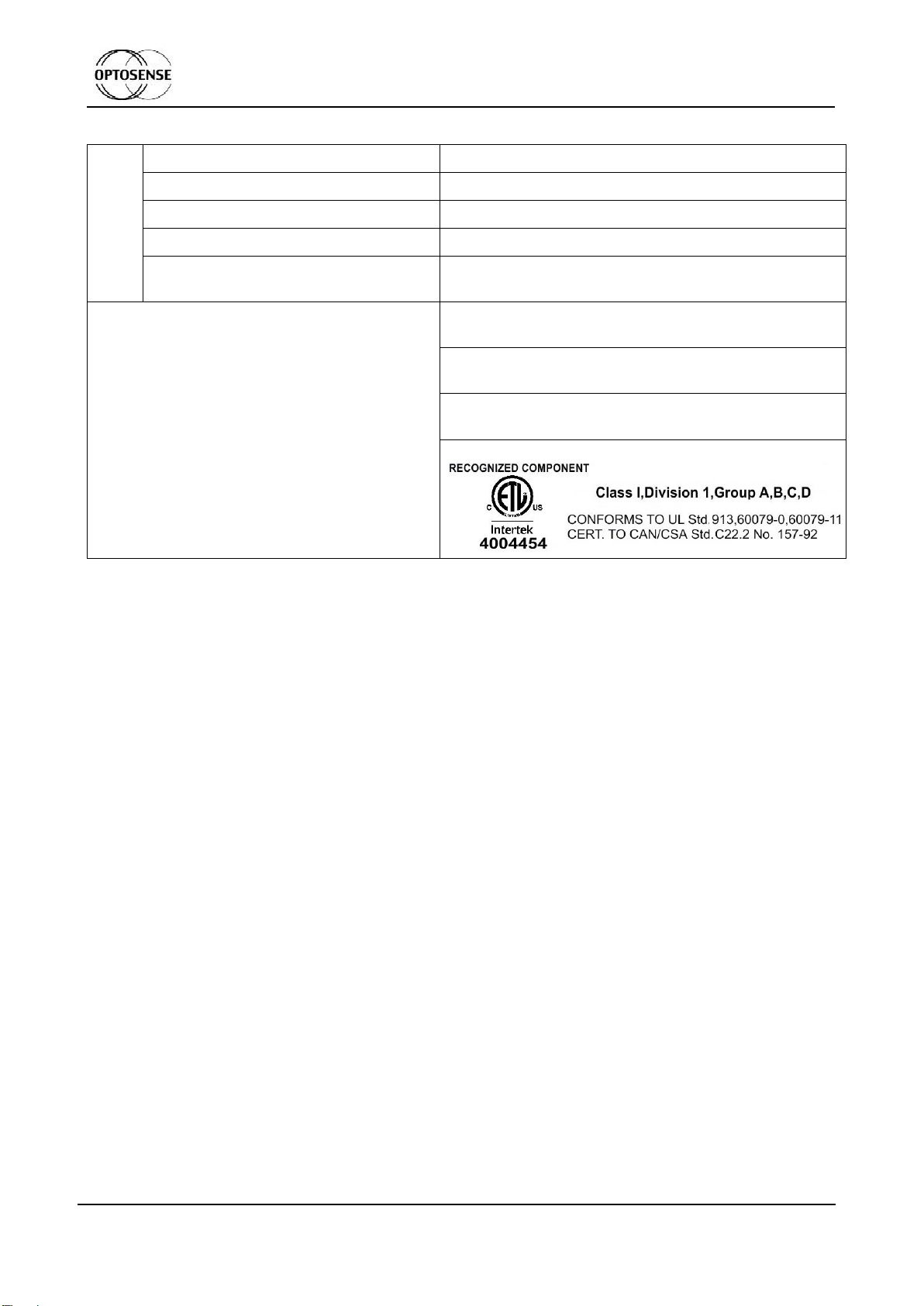
3. INTRINSIC SAFETY...............................................................................................................8
4. PRECAUTIONS......................................................................................................................9
5. INSTALLATION AND SERVICES ........................................................................................10
6. STORAGE AND TRANSPORTATION..................................................................................12
7. WARRANTY.........................................................................................................................13
8. CONTACTS..........................................................................................................................14
APPENDIX A. SENSOR TYPES AND CHARACTERISTICS................................................15
APPENDIX B. CONNECTION DIAGRAM.............................................................................21
APPENDIX C. UART COMMUNICATION PROTOCOL........................................................24
C.1. General information...........................................................................................................24
C.2. Work modes......................................................................................................................24
C.3. Protocol commands...........................................................................................................24
C.3.1. Operating commands ........................................................................................24
C.3.2. Request commands of factory settings and properties.......................................28
C.3.3. Sensor setting and calibration commands .........................................................30
C.4. Firmware update ...............................................................................................................32
C.5. Troubleshooting ................................................................................................................33
APPENDIX D. SENSOR ZEROING AND CALIBRATION.....................................................34
D.1. Zeroing..............................................................................................................................34
D.1.1. Autozero............................................................................................................34
D.1.2. Manual zeroing in whole temperature range......................................................35
D.1.3. Manual zeroing in different points of temperature range....................................35
D.2. Scaling..............................................................................................................................35
APPENDIX E. DUST FILTERS.................................................................................................38
List of abbreviations:
CGM –Control Gas Mixture;
EMI - Electromagnetic Interference;
LEL –Lower Explosive Limit;
NDIR - Non-Dispersive Infra-Red;
UART - Universal Asynchronous Receiver/Transmitter.

OPTOSENSE LLC
Design Department
USER MANUAL
SMALL-SIZE EXPLOSIVE GAS MEASURING SENSOR MIPEX-02-Х-X-X.1 X
File name: ESAT.413347.006 UM v.2.0.docx
Revision 2.0 27 August 2015
Page. 4 of 38
THE SOLE PROPERTY OF OPTOSENSE LLC. ANY REPRODUCTION WITHOUT THE WRITTEN PERMISSION OF OPTOSENSE LLC IS PROHIBITED.
INTRODUCTION
MIPEX-02-Х-Х-X.1 X (hereinafter, sensor or MIPEX-02) is the gas sensor, which is intended
for automatic continuous measurement of concentration of hydrocarbons in explosive areas and
carbon dioxide. The sensor is used for gas detection in atmosphere.
Sensor can be used as part of gas-analyzing equipment of groups I and II according to IEC
60079-0 in the explosion-hazardous zones of classes 0, 1, 2 according to IEC 60079-10-1, and
Class I, Division 1 according to UL Std. 913, CAN/CSA Std. C22.2 No.157-92.
Optosense LLC reserves the right to update and change current user manual in parts
excluding intrinsic safety parameters and accompanied information specified below.

OPTOSENSE LLC
Design Department
USER MANUAL
SMALL-SIZE EXPLOSIVE GAS MEASURING SENSOR MIPEX-02-Х-X-X.1 X
File name: ESAT.413347.006 UM v.2.0.docx
Revision 2.0 27 August 2015
Page. 5 of 38
THE SOLE PROPERTY OF OPTOSENSE LLC. ANY REPRODUCTION WITHOUT THE WRITTEN PERMISSION OF OPTOSENSE LLC IS PROHIBITED.
1. DESCRIPTION
The principle of sensor operation is based on NDIR technology.
Infrared radiation of the LED passed through the measuring gas diffusion cell and reaches
the two of photodetectors, one of which detects radiation in the wavelength range of 3.25 to
3.45 m only, while the other one detects radiation in the wavelength range of 3.45 to 3.7 m. The
analyzed gas that is present in the measuring cell absorbs radiation of the operating wavelength
(o) and does not affect radiation of the reference operating wavelength (r). The amplitude Io of
the light-sensitive cell operating signal changes upon changing concentration in accordance with
equation:
Io/Ir = ехр {-[К(o) –К (r)]СL};
(1)
where:
К ()–coefficient of absorption at a given wavelength;
L –optical length of cell;
С–measured concentration of gas;
Io, Ir –amplitude of signals at light-sensitive cell.
The concentration of gas is:
С = -Ln (Io/Ir)/(L [K (o) –К (r)]);
(2)
Using differential dual wavelength method allows eliminating influence of water vapor,
contamination of optical elements and other non-selective hindrances affecting both channels
similarly.
The sensor structure contains an optical cell with a mirror system, infrared light-emitting
diode (LED), LED driver, receivers of Signal and Reference channels, analog amplifiers,
microcontroller and supply voltages unit.
The microcontroller of the sensor performs:
- storage of unique calibration constants;
- calculation of gas concentration based on measured results;
- communication via UART output interface.

OPTOSENSE LLC
Design Department
USER MANUAL
SMALL-SIZE EXPLOSIVE GAS MEASURING SENSOR MIPEX-02-Х-X-X.1 X
File name: ESAT.413347.006 UM v.2.0.docx
Revision 2.0 27 August 2015
Page. 6 of 38
THE SOLE PROPERTY OF OPTOSENSE LLC. ANY REPRODUCTION WITHOUT THE WRITTEN PERMISSION OF OPTOSENSE LLC IS PROHIBITED.
2. TECHNICAL SPECIFICATIONS
Table 1. Technical specification (available options see Appendix A).
General
Gas sampling method:
Diffusion
Operating principle:
Non-Dispersive Infra-Red (NDIR)
Target gas
CH4
CH4/CH4+С2Н6
C3H8
CO2
Operating,
storage and
transportation
conditions:
Relative humidity, %
up to 98
Atmospheric
pressure, kPa
80-120
Operating
temperature*, °C
-55... +60
Temperature range*, °C
-10… +40
-40… +60
-20… +50
Overall dimensions, mm
ø20х16.5 without pins (standard and plastic versions)
ø22х16.5 without pins (fast response versions)
Pins length, mm
4,6
5.75
Weight, g
16,6
15,5
5,5
Housing
Stainless steel (standard and fast response versions)
Plastic
MTBF, years
10
Ingress protection (IP) rating
20 (without dust filter)
54 (with dust filter)
Measurement
Measurement range, % Vol
0-1.5
0-2.5
0-5
0-100
Accuracy (UART data)
Up to 0.05% Vol or 5% of indication for CO2 and C3H8
Up to 0.1% Vol or 5% of indication for CH4
Response time (T90), s
10
20
30
60

OPTOSENSE LLC
Design Department
USER MANUAL
SMALL-SIZE EXPLOSIVE GAS MEASURING SENSOR MIPEX-02-Х-X-X.1 X
File name: ESAT.413347.006 UM v.2.0.docx
Revision 2.0 27 August 2015
Page. 7 of 38
THE SOLE PROPERTY OF OPTOSENSE LLC. ANY REPRODUCTION WITHOUT THE WRITTEN PERMISSION OF OPTOSENSE LLC IS PROHIBITED.
Electrical
Supply Voltage Range:
+3.0…+5.0 VDC
Output signal
digital UART
Power consumption, mW
<5
Warm-up time (not more), min
2
Degree of personal protection against
electrical shock caused by the sensor
meets the requirement of class III GOST 12.2.007.0
Marking and standards
compliance
Ex ia I U/Ex ia IIC U. acc. to ГОСТ РМЭК 60079-0,
ГОСТ РМЭК 60079-11, ТР ТС 012/2011
Ex ia I Ma/Ex ia IIC Ga. acc. to IEC60079-0, IEC60079-
11, IEC60079-26. -55⁰≤ Ta ≤ +60 ⁰C
IM 1/II 1 G Ex ia I Ma / Ex ia IIC Ga. acc. to EN60079-0,
EN60079-11, EN60079-26. -55⁰≤ Ta ≤ +60 ⁰C
* Term operation temperature means the ambient temperature where the sensor can be used
safely, but the sensor accuracy supported only in temperature range (see Table 3 and Table 5).

OPTOSENSE LLC
Design Department
USER MANUAL
SMALL-SIZE EXPLOSIVE GAS MEASURING SENSOR MIPEX-02-Х-X-X.1 X
File name: ESAT.413347.006 UM v.2.0.docx
Revision 2.0 27 August 2015
Page. 8 of 38
THE SOLE PROPERTY OF OPTOSENSE LLC. ANY REPRODUCTION WITHOUT THE WRITTEN PERMISSION OF OPTOSENSE LLC IS PROHIBITED.
3. INTRINSIC SAFETY
Combined intrinsically safe parameters of sensor circuits are as follows:
IECEx/ATEX: Ui = 5.0V, Ii = 450mA, Pi = 0.25W, Ci = 38.8µF, Li = 0 mH.
CAN/CSA: Vmax = 5.0V, Imax = 450mA, Pmax = 0.25W, Ci = 38.8µF, Li = 0 mH.
It is allowed to connect the sensor only to intrinsically safe circuits with the rated direct
current output voltage (U0) within the range of not less than 3 V and not more than 5 V, with the
output power (P0) - not less than 0.02 W and not more than 0.25 W.
The gas-analyzing equipment, which is used with MIPEX-02, must meet the requirements of
IEC60079–0, IEC60079–11, IEC 60079-14 and have parameters conforming the MIPEX-02
intrinsic safety pointed above.

OPTOSENSE LLC
Design Department
USER MANUAL
SMALL-SIZE EXPLOSIVE GAS MEASURING SENSOR MIPEX-02-Х-X-X.1 X
File name: ESAT.413347.006 UM v.2.0.docx
Revision 2.0 27 August 2015
Page. 9 of 38
THE SOLE PROPERTY OF OPTOSENSE LLC. ANY REPRODUCTION WITHOUT THE WRITTEN PERMISSION OF OPTOSENSE LLC IS PROHIBITED.
4. PRECAUTIONS
Inspection and maintenance of the sensor should be carried out by suitably trained
personnel in accordance with the applicable code of practice (e.g. EN 60079-17).
Any person who have studied this UM, have been briefed on safety precautions when
operating electrical equipment intended for operation in the explosion-hazardous zones in
the established order, is admitted to operate the sensor.
Do not use damaged sensor. Unauthorized repair of the sensor is not allowed.
It is strongly prohibited to discharge the control gas mixture (CGM) to the atmosphere
during the sensor calibration.
Do not allow the contact of the sensor with aggressive substances e.g. acidic liquids or
gases that might attack metals, or solvents that might affect polymeric materials.
The sensor does not contain any poisons and other harmful substances that might be
released from the sensor during its operation. Risk to humans and environment does not
exist.

OPTOSENSE LLC
Design Department
USER MANUAL
SMALL-SIZE EXPLOSIVE GAS MEASURING SENSOR MIPEX-02-Х-X-X.1 X
File name: ESAT.413347.006 UM v.2.0.docx
Revision 2.0 27 August 2015
Page. 10 of 38
THE SOLE PROPERTY OF OPTOSENSE LLC. ANY REPRODUCTION WITHOUT THE WRITTEN PERMISSION OF OPTOSENSE LLC IS PROHIBITED.
5. INSTALLATION AND SERVICES
5.1 Preparation
5.1.1 If the sensor has been kept in the transportation package at temperature lower than
00C, hold it at temperature of 10–35 0C for at least one hour.
5.1.2 Remove the packing. Check presence of the certification marking, ensure absence
of mechanical injuries.
5.2 Installation
Use intrinsic safety connection (see Appendix B for details).
5.2.1 Use the following recommended sockets for the sensor connection or similar:
Cambion 450-3729-01-06-00;
Harwin H3183-05;
Harwin H3182 (for the MIPEX-02-X-X-X.1 A modification).
Sensor pinout is shown in Fig. 1 of Appendix A.
5.2.2 Provide intrinsically safe power supply to the sensor from power sources featuring
nominal range of output DC voltage of not less than 3 V and not more than 5 V,
output power (P0) –not less than 0.02 W and not more than 0.25 W in accordance
with requirements of standards IEC 60079–0:2004, IEC 60079–11:2006.
5.2.3 The transceiver of UART interface should meet the requirements of standards
IEC 60079–0, IEC 60079–11.
Communication parameters of UART- transceiver are following:
- HIGH logic level for transmit line TxD is 2.8V;
- HIGH logic level for receive line RxD should be in range between 2.8V and 3.3 V;
Models MIPEX-02-X-X-3.1 X are potential electrostatic charging hazard –
clean them with a damp cloth only. Take it into account during installation
and operation of the sensor in end-user equipment.
The MIPEX-02-X-X-1.1 X and MIPEX-02-X-X-2.1 X models of the
equipment were tested and found to hold 17.4pF maximum capacitance.
Connection should be made via PCB sockets. Soldering to the pins will
seriously damage the sensor.
Excessive force on sensor housing is not allowed. For the metal housing -
no more than 2 MPa applied to reflecting cover center or on at any point of
middle part side surface and no more 100 MPa applied to boundary of
reflecting cover. For the plastic housing - no more than 20 kPa applied to
reflecting cover center or on at any point of side surface and no more 2
MPa applied to boundary of reflecting cover.
Metrological properties are not supported in ambient temperature gradient
faster than 0.6 ⁰C/min.
Set manual zeroing procedure after continues storage or transportation.

OPTOSENSE LLC
Design Department
USER MANUAL
SMALL-SIZE EXPLOSIVE GAS MEASURING SENSOR MIPEX-02-Х-X-X.1 X
File name: ESAT.413347.006 UM v.2.0.docx
Revision 2.0 27 August 2015
Page. 11 of 38
THE SOLE PROPERTY OF OPTOSENSE LLC. ANY REPRODUCTION WITHOUT THE WRITTEN PERMISSION OF OPTOSENSE LLC IS PROHIBITED.
- LOW logic level 0.9 V;
- Maximum output current of UART not more than 25 mA.
5.3 Proper use
It is recommended to use filter to protect the optical components of the sensor from dust,
excess moisture and other factors that could affect on readings accuracy. Take measures for
sensors dust protection in the equipment with forced gas pumping. A regular monitoring of the filter
and it’s replacement is necessary (filter installation –see Appendix E).
The sensor outputs information about measured concentration value though the digital serial
interface UART. Data communication protocol is given in Appendix C.
The sensor is designed for continuous operation.
There is self-testing algorithm inside the firmware code.
Since 24.2 firmware version there is additional mode of low power consumption (to set low
power mode see C.3.2 of Appendix C). In low power mode sensor consumption is not more than
1.8 mW, but performance could be deteriorated.
Low power mode could be used as explosive gas indication mode even with deep battery
discharge in device.
MIPEX-02 has pulsing power consumption. Maximum current might shortly
rise up to 10 mA during 10 ms pulse length. Average consumption is less
than 1 mA (see Fig. 8).
In case if the sensor sends response for the commands via UART
maximum current consumption might rise up to 10 mA for 60 ms.
Since the power is supplied, during 40s the sensor does not return the
concentration value (the value is being displayed as “-1”). After that sensor
starts to transfer measured values.
Please note that if the dust filter from sensor’s kit was attached, then
ZERO2 command must be send after warm-up time.
Sensor updates information about concentration approx. every 1.3 sec.
Sending commands more often than 1 time per sec (sampling rate over
1Hz) is not recommended, otherwise the temperature sensor accuracy
comes down.
The setting of zero and calibration of the sensor is performed in the course of the
primary installation into a gas analyzer as well as annually during preparation to
conducting a check. In any cases the setting zero should be done before
calibration. Methods of setting zero of the sensor and re-calibration are given in
Appendix D).

OPTOSENSE LLC
Design Department
USER MANUAL
SMALL-SIZE EXPLOSIVE GAS MEASURING SENSOR MIPEX-02-Х-X-X.1 X
File name: ESAT.413347.006 UM v.2.0.docx
Revision 2.0 27 August 2015
Page. 12 of 38
THE SOLE PROPERTY OF OPTOSENSE LLC. ANY REPRODUCTION WITHOUT THE WRITTEN PERMISSION OF OPTOSENSE LLC IS PROHIBITED.
6. STORAGE AND TRANSPORTATION
The transportation of the sensors should be performed by all means of transportation in
covered transportation vehicles as well as in the heated pressurized plane compartments in
accordance with the rules of cargoes transportation effective for the respective type of
transportation.
The sensors in the Manufacturer’s package should be kept in the Supplier’s and Customer’s
storages under storage conditions pointed in Table 1. The atmosphere of storage premises should
be free from harmful admixtures provoking corrosion.

OPTOSENSE LLC
Design Department
USER MANUAL
SMALL-SIZE EXPLOSIVE GAS MEASURING SENSOR MIPEX-02-Х-X-X.1 X
File name: ESAT.413347.006 UM v.2.0.docx
Revision 2.0 27 August 2015
Page. 13 of 38
THE SOLE PROPERTY OF OPTOSENSE LLC. ANY REPRODUCTION WITHOUT THE WRITTEN PERMISSION OF OPTOSENSE LLC IS PROHIBITED.
7. WARRANTY
The Manufacturer guarantees compliance of the sensors with specifications and
requirements stated in this UM if Customer meets conditions of operation, transportation and
storage.
During the warranty period, Customer has the right to get replace or repair of all the products
that, according to its unquestionable valuation, are found to be defective, if defect is due to a fault
of Manufacturer.
The warranty period is 24 months since the date of sensor shipment to a Customer. The date
of shipment is registered in the ESAT.413347.005 PS datasheet.
Manufacturer is not responsible for the sensors failure and warranty is void in case of:
violations of conditions of operation, transportation and storage stated in UM;
sensor has marks of unauthorized repair;
mechanical damages, appeared after handover the sensors to Customer, effect of
temperature and pressure beyond conditions, chemical erosion, ingress of foreign
substances inside the body of the sensor;
defects due to electrical interface unspecified by UM and other documentation
conveyed to the Customer;
defects due to force majeure circumstances, disastrous occurrences, intended or
reckless act of Customer or third party;
defect or failure due to installing, damaging, changing or erasing of sensors firmware
or changing sensors settings because of misuse of service codes via UART.
defect or failure due to using power or signal cables unspecified by technical
regulations and standards or operating the sensor with EMC influences exceeds
maximums specified in IEC 61000-4-3, class II.
Replacement or repair of defective sensor does not lead to setting a new warranty period.
The Manufacturer is not responsible for possible damages, direct or indirect inflicted to
people or properties if this is happened in case of repair, storage and transportation rules violation
or due to purport or reckless act of Customer or third party. The Manufacturer does not respond as
well for possible damages, direct or indirect inflict to appropriate equipment as the result of
change, damage or data loss.
The warranty repair or replacement is effecting in site of Manufacturer or designated
representative.
Every shipping and packaging charge and any other incidental expenses if the products must
be returned to Manufacturer will be at the Customer’s own risk and charged to them.

OPTOSENSE LLC
Design Department
USER MANUAL
SMALL-SIZE EXPLOSIVE GAS MEASURING SENSOR MIPEX-02-Х-X-X.1 X
File name: ESAT.413347.006 UM v.2.0.docx
Revision 2.0 27 August 2015
Page. 14 of 38
THE SOLE PROPERTY OF OPTOSENSE LLC. ANY REPRODUCTION WITHOUT THE WRITTEN PERMISSION OF OPTOSENSE LLC IS PROHIBITED.
8. CONTACTS
MIPEX Technology /Оptosense LLC
27, AD, Engelsa prospect, St. Petersburg, 194156, Russia,
Tel./fax: +7 (812) 633-0594, 633-0595
web: http://www.mipex-tech.com
e-mail: info@mipex-tech.com
support: suppo[email protected]

OPTOSENSE LLC
Design Department
USER MANUAL
SMALL-SIZE EXPLOSIVE GAS MEASURING SENSOR MIPEX-02-Х-X-X.1 X
File name: ESAT.413347.006 UM v.2.0.docx
Revision 2.0 27 August 2015
Page. 15 of 38
THE SOLE PROPERTY OF OPTOSENSE LLC. ANY REPRODUCTION WITHOUT THE WRITTEN PERMISSION OF OPTOSENSE LLC IS PROHIBITED.
Appendix A. Sensor types and characteristics.
MIPEX-02-B-C-D.1 A
Pins length version:
If not specified - 5.75 mm pins;
A –4.6 mm pins.
Output format:
1 –UART.
Construction:
1. - stainless steel, “Standard”;
2. - stainless steel, with side holes, “Fast
response”;
3. –plastic.
Application:
I –Group I, for mines;
II –Group II, for places with a potentially
explosive atmosphere, other than mines;
(see Table 3 for details).
Target gas*:
1. - CH4, methane;
2. - C3H8, (CnHm, hydrocarbons);
3. - CO2, carbon dioxide;
4. - CH4/CH4 +С2Н6 acc. to IEC 60079-29-1
MIPEX model number
* Term target gas means the model of the LED and photodiode with the spectral range
adjusted for best gas detection. Term calibration gas –is the gas mixture used for the sensor
calibration.
There is an additional RX code presented on the sensor label. The code explains application
properties (see Table 3 for details):
R–calibration gas and range;
X- temperature class and accuracy.

OPTOSENSE LLC
Design Department
USER MANUAL
SMALL-SIZE EXPLOSIVE GAS MEASURING SENSOR MIPEX-02-Х-X-X.1 X
File name: ESAT.413347.006 UM v.2.0.docx
Revision 2.0 27 August 2015
Page. 16 of 38
THE SOLE PROPERTY OF OPTOSENSE LLC. ANY REPRODUCTION WITHOUT THE WRITTEN PERMISSION OF OPTOSENSE LLC IS PROHIBITED.
Table 2. MIPEX-02-X-X-X.1 X types and overall dimensions.

OPTOSENSE LLC
Design Department
USER MANUAL
SMALL-SIZE EXPLOSIVE GAS MEASURING SENSOR MIPEX-02-Х-X-X.1 X
File name: ESAT.413347.006 UM v.2.0.docx
Revision 2.0 27 August 2015
Page. 17 of 38
THE SOLE PROPERTY OF OPTOSENSE LLC. ANY REPRODUCTION WITHOUT THE WRITTEN PERMISSION OF OPTOSENSE LLC IS PROHIBITED.
Fig. 1. Sensor pinout.
Table 3. Individual specifications of the sensor (RX code).
Target
gas
Calibration
gas
Measurement
range
RX code
(marking)
Temperature
range, ⁰C
Application
CH4
or
CH4/СН4+С2H6
CH4
0-2.5 % Vol
00
-10… +40
I
0-5 % Vol
10
0-100 % Vol
20
CO2
CO2
0-1.5 % Vol
30
CH4
or
CH4/СН4+С2H6
CH4
0-2.5% Vol
01
-40… +60
II
0-5 % Vol
11
0-100 % Vol
21
CH4
or
C3H8
C3H8
0-1.5 % Vol
61
0-2.5 % Vol
71
CH4
or
CH4/СН4+С2H6
CH4
0-2.5% Vol
02
-20… +50
0-5 % Vol
12
0-100 % Vol
22
CO2
CO2
0-1.5 % Vol
32
CH4
or
C3H8
C3H8
0-1.5 % Vol
62
0-2.5 % Vol
72
Typical sensor sensitivity to other hydrocarbons is shown on Fig. 2, Fig. 3 and Fig. 4.

OPTOSENSE LLC
Design Department
USER MANUAL
SMALL-SIZE EXPLOSIVE GAS MEASURING SENSOR MIPEX-02-Х-X-X.1 X
File name: ESAT.413347.006 UM v.2.0.docx
Revision 2.0 27 August 2015
Page. 18 of 38
THE SOLE PROPERTY OF OPTOSENSE LLC. ANY REPRODUCTION WITHOUT THE WRITTEN PERMISSION OF OPTOSENSE LLC IS PROHIBITED.
Table 4. Response time of the sensors.
Construction
Target gas
Max. response
time t(90), sec
stainless steel, “Standard” and
plastic
CH4
30
CH4/СН4+С2H6
C3H8
CO2
60
stainless steel, with side holes,
“Fast response”
CH4
10
CH4/СН4+С2H6
C3H8
CO2
20
Table 5. General sensor accuracy* depends on calibration gas
Calibration
gas
Accuracy over temperature
range
Additional pressure
error
Additional humidity
error
CH4
±0,1%Vol. or ±5% of
indication in range
+20…+25°C;
±0,2% Vol. or ±10% of
indication in range
–10…+20°C and
+25…+40°C;
±0,4% Vol. or ±20% of
indication in range
-40…-10°C and +40…+60°C.
±0,2% Vol. or ±30% of
indication from
100kPa (test: 80kPa,
100kPa, 120kPa)
±0,2 % Vol. or ±15 %
of indication from the
indication at
adjustment at 40 °C
(test: 20 %RH, 50
%RH,90 %RH)
CO2, C3H8
±0,05% Vol. or ±5% of
indication in range
+20…+25°C;
±0,1% Vol. or ±10% of
indication in range
–10…+20°C and
+25…+40°C;
±0,2% Vol. or ±20% of
indication in range
-40…-10°C and +40…+60°C.
±0,1% Vol. or ±30% of
indication from
100kPa (test: 80kPa,
100kPa, 120kPa)
±0,1 % Vol. or ±15 %
of indication from the
indication at
adjustment at 40 °C
(test: 20 %RH, 50
%RH,90 %RH)
*Table shows the general accuracy, but individual sensor accuracy depends on RX characteristic
and limited by the temperature range (see Table 3).

OPTOSENSE LLC
Design Department
USER MANUAL
SMALL-SIZE EXPLOSIVE GAS MEASURING SENSOR MIPEX-02-Х-X-X.1 X
File name: ESAT.413347.006 UM v.2.0.docx
Revision 2.0 27 August 2015
Page. 19 of 38
THE SOLE PROPERTY OF OPTOSENSE LLC. ANY REPRODUCTION WITHOUT THE WRITTEN PERMISSION OF OPTOSENSE LLC IS PROHIBITED.
Fig. 2. Typical sensitivity of MIPEX-02-1-X-X.X X (target and calibration gases –CH4) to other
hydrocarbons.
Fig. 3. Typical sensitivity of MIPEX-02-1-X-X.X X(target and calibration gases –C3H8) to other
hydrocarbons.
0
10
20
30
40
50
60
70
80
90
100
110
120
130
140
150
010 20 30 40 50 60 70 80 90 100
Responce concentration, % LEL
Calibrated concentration, % LEL
CH4
C3H8
C2H6
C4H10
C6H14
C2H4
CH4
0
10
20
30
40
50
60
70
80
90
100
110
010 20 30 40 50 60 70 80 90 100
Responce concentration, % LEL
Calibrated concentration, % LEL
C3H8
C4H10
C5H12
C6H14
CH4

OPTOSENSE LLC
Design Department
USER MANUAL
SMALL-SIZE EXPLOSIVE GAS MEASURING SENSOR MIPEX-02-Х-X-X.1 X
File name: ESAT.413347.006 UM v.2.0.docx
Revision 2.0 27 August 2015
Page. 20 of 38
THE SOLE PROPERTY OF OPTOSENSE LLC. ANY REPRODUCTION WITHOUT THE WRITTEN PERMISSION OF OPTOSENSE LLC IS PROHIBITED.
Fig. 4. Typical sensitivity of MIPEX-02-4-X-X.X X(target gas - CH4/СН4+С2H6, calibration gas – CH4)
to other hydrocarbons.
0
10
20
30
40
50
60
70
80
90
100
110
010 20 30 40 50 60 70 80 90 100
Responce concentration, % LEL
Calibrated concentration, % LEL
CH4
C3H8
C2H6
C4H10
C6H14
C2H4
CH4
Table of contents
Other Mipex Accessories manuals
Popular Accessories manuals by other brands

Manhattan
Manhattan 411097 instructions

Western Co
Western Co Leonardo Off-Grid 8kW-8000-48 MG user manual

PCB Piezotronics
PCB Piezotronics IMI Sensors 640 B7 Series Installation and operating manual

Lovibond
Lovibond DI 10 quick start guide

Baumer
Baumer URDK 30P6104/S14 quick start guide

Ubiquiti
Ubiquiti mFi-DS quick start guide