dymax Edge-Carry User manual

Dymax Edge-Carry Conveyor User Guide
UV Light-Curing Conveyor System
▪Instructions for Safe Use
▪Setup and Operation
▪Maintenance
▪Ordering Spare Parts and Accessories

2
Dymax Edge-Carry Conveyor User Guide
About Dymax
UV/Visible light-curable adhesives. Systems for light curing, fluid dispensing, and fluid packaging.
Dymax manufactures industrial adhesives, light-curable adhesives, epoxy resins, cyanoacrylates, and activator-cured adhesives.
We also manufacture a complete line of manual fluid dispensing systems, automatic fluid dispensing systems, and light-curing systems.
Light-curing systems include LED light sources, spot, flood, and conveyor systems designed for compatibility and high performance
with Dymax adhesives
Dymax adhesives and light-curing systems optimize the speed of automated assembly, allow for 100% in-line inspection, and increase
throughput. System designs enable stand-alone configuration or integration into your existing assembly line.
Please note that most dispensing and curing system applications are unique. Dymax does not warrant the fitness of the product for the
intended application. Any warranty applicable to the product, its application and use is strictly limited to that contained in the Dymax
standard Conditions of Sale. Dymax recommends that any intended application be evaluated and tested by the user to insure that desired
performance criteria are satisfied. Dymax is willing to assist users in their performance testing and evaluation by offering equipment trial
rental and leasing programs to assist in such testing and evaluations. Data sheets are available for valve controllers or pressure pots upon
request.

3
Dymax Edge-Carry Conveyor User Guide
Contents
Introduction....................................................................................................................................................4
Introduction to the User Guide ....................................................................................................................................... 4
Where to Get Help .......................................................................................................................................................... 4
Safety..............................................................................................................................................................4
General Safety Considerations ........................................................................................................................................ 4
Dymax UV Light-Curing System Safety Considerations ................................................................................................... 5
Product Overview ...........................................................................................................................................7
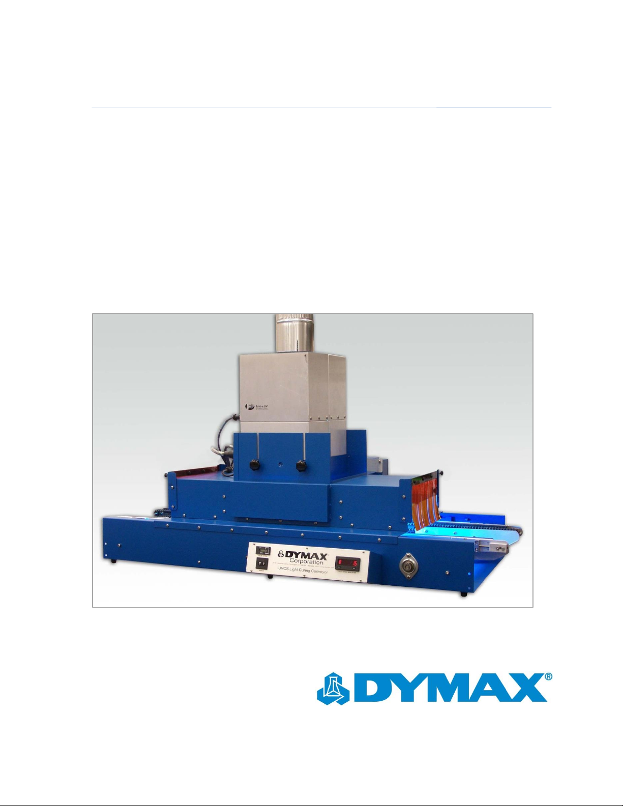
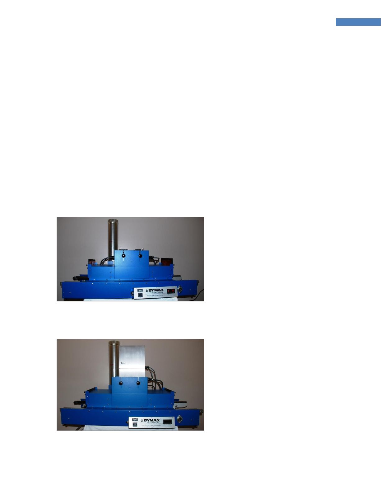
Description of the Edge-Carry Conveyor ......................................................................................................................... 7
Specifications..................................................................................................................................................8
General............................................................................................................................................................................ 8
Electrical Specifications ................................................................................................................................................... 9
Physical Specifications..................................................................................................................................................... 9
Unpacking..................................................................................................................................................... 12
Unpacking and Inspecting Your Shipment..................................................................................................................... 12
Parts Included in the Edge-Carry Conveyor................................................................................................................... 12
Setup and Interconnect................................................................................................................................. 12
Conveyors Using Dymax EC-Series Flood Lamps ........................................................................................................... 12
Conveyors Using Fusion Flood Lamps............................................................................................................................ 15
Belt Speed Adjustment.................................................................................................................................................. 18
Conveyor Configurations............................................................................................................................... 19
2A Lamp Configuration: Two 5000-EC Lamps In-Line.................................................................................................... 19
2B Lamp Configuration: Two 5000-EC Lamps Side-By-Side........................................................................................... 19
Four 5000-EC Lamp Configuration................................................................................................................................. 20
Single 2000-EC or 1200-EC Lamp Configuration............................................................................................................ 20
Dual Fusion Lamp Configuration ................................................................................................................................... 20
Single Fusion Lamp Configuration ................................................................................................................................. 21
Conveyor Operation...................................................................................................................................... 22
Operating Instructions for Conveyors Using Dymax 5000-, 2000-, Or 1200-EC Lamp Systems..................................... 22
Operating Instructions for Conveyors Using Fusion Lamp Systems .............................................................................. 25
Maintenance................................................................................................................................................. 26
Chain Carrier Position Adjustment ................................................................................................................................ 26
Chain Tension Adjustment ............................................................................................................................................ 26
Troubleshooting............................................................................................................................................27
Spare Parts and Accessories.......................................................................................................................... 28
EC-Series Flood Lamp Replacement Parts ..................................................................................................................... 28
Fusion Lamp Replacement Parts ................................................................................................................................... 29
Conveyor Replacement Parts/Accessories .................................................................................................................... 29
Definition of Terms....................................................................................................................................... 30
Warranty ...................................................................................................................................................... 31
Index............................................................................................................................................................. 31

4
Dymax Edge-Carry Conveyor User Guide
Introduction
Introduction to the User Guide
This guide describes how to use the Dymax Edge-Carry Conveyor. Sections in this guide describe how to
assemble, use, and maintain the conveyor safely and efficiently.
Intended Audience
Dymax prepared this user guide for experienced process engineers, technicians, and manufacturing personnel.
If you are new to UV light curing and do not understand the instructions, contact Dymax Application
Engineering to answer your questions before using the equipment.
Where to Get Help
Dymax Customer Support and Application Engineering teams are available in the United States, Monday
through Friday, from 8:00 a.m. to 5:30 p.m. Eastern Standard Time. You can also email Dymax at
[email protected]. Contact information for additional Dymax locations can be found on the back cover of this
user guide.
Additional resources are available to ensure a trouble-free experience with our products:
◼Detailed product information on www.dymax.com
◼Dymax adhesive Product Data Sheets (PDS) on our website
◼Material Safety Data Sheets (MSDS) provided with shipments of Dymax adhesives
Safety
WARNING! If you use this light-curing system without first reading and understanding the
information in this user guide, injury can result from exposure to high-intensity light. To reduce
the risk of injury, read and ensure you understand the information in this user guide before
assembling and operating a Dymax UV conveyor system.
To use this conveyor system safely, it must be set up and operated in accordance with the
instructions given by Dymax. Using the system in any other manner will impair the protection of
the system. Dymax assumes no liability for any changes that may impair the protection of the
system.
General Safety Considerations
The Edge-Carry conveyor is designed to maximize operator safety and minimize exposure to light-curing
energy. To use the unit safely, it must be set up and operated in accordance with the instructions in this user
guide. All users of Dymax equipment should read and understand this user guide before assembling and using
the equipment.
!

5
Dymax Edge-Carry Conveyor User Guide
To learn about the safe handling and use of light-curable formulations, obtain and read the MSDS for each
product. Dymax includes an MSDS with each adhesive sold. In addition, fluid product MSDS can be requested
through the Dymax website.
Dymax UV Light-Curing System Safety Considerations
Dymax UV light-curing technology has been used successfully for over 30 years. The fast cure, one-component
nature of our UV light-curing technology has made it the process of choice for many manufacturers requiring a
"cure on demand" assembly process. Operators must understand these four concepts to use the UV light
source safely: UV exposure, high-temperature surfaces, ozone, and bright, visible light. Each is described
below.
UV Exposure
Standard Dymax UV light-curing systems have been designed primarily to emit UVA energy (Figure 1). UVA
energy is generally considered the safest of the three UV ranges: UVA, UVB, and UVC. Although OSHA does not
currently regulate UV light exposure in the workplace, the American Conference of Governmental Industrial
Hygienists (ACGIH) does recommend Threshold Limit Values (TLVs) for ultraviolet light.
The strictest interpretation of the TLV (over the UVA range) for workers’ eyes and skin allows continuous
exposure up to 1 mW/cm2(intensity). Unless you are placing bare hands into the curing area, it is unusual to
exceed these limits. To put 1 mW/cm2limit into perspective, a cloudless summer day will typically exceed
3 mW/cm2of UVA light, and also include the more dangerous UVB light (primarily responsible for sun tans,
sun burns, and skin cancer) as well.
Figure 1. UV Spectrum
Checking the Workstation
The human eye cannot detect "pure" UV light, only visible light. A radiometer should be used to measure stray
UV light to confirm the safety of a UV light-curing process. A workstation that exposes an operator to more
than 1 mW/cm2of UVA continuously should be redesigned.
Protecting Operators
Light-curing technology can be a regulatory compliant, "worker-friendly" manufacturing process when the
proper safety equipment and operator training is utilized. There are two ways to protect operators from UV
exposure: shield the operator and/or shield the source.

6
Dymax Edge-Carry Conveyor User Guide
Shield the Operator —UV-Blocking Eye Protection - UV-blocking eye protection is recommended when
operating UV light-curing systems. Both clear and tinted UV-blocking eye protection is available from Dymax.
UV-Blocking Skin Protection —Where the potential exists for UV exposure upon skin, opaque, UV-blocking
clothing, gloves, and full-face shields are recommended.
Shield the Source of UV
Any substrate that blocks UV light can be used as a shield to protect workers from stray UV light. The following
materials can be used to create simple shielding structures or blind corners:
Sheet Metal —Sheet metal (aluminum, steel, stainless steel, etc) should be coated black or black anodized to
minimize reflection of UV and visible light toward operators.
Rigid Plastic Film —Transparent or translucent/UV-blocking plastics (typically polycarbonate or acrylic) are
commonly used to create shielding where some level of transparency is also desired. These rigid plastic films
are available wither water clear or tinted.
Flexible Film —UV-blocking, flexible urethane films can be used to quickly create workstation shielding. This
UV-blocking, flexible urethane film is available from Dymax, call for assistance.
High-Temperature Surfaces
Surfaces exposed to high-intensity curing lights may rise in temperature. The intensity, distance, exposure
time, cooling fans, and composition of the surface can all affect the rise in surface temperature. In some cases,
exposed surfaces can reach temperatures capable of producing a burn or causing damage to a substrate. In
these cases, care must be taken to ensure either a more moderate surface temperature or appropriate
protection/training for operators.
Ozone
Standard Dymax lamps (UVA type) generate an insignificant amount of UVC and therefore essentially no
ozone. Some UV light-curing systems, like those used to cure UV inks, emit primarily “shortwave” (UVB and
UVC) energy. Upon exposure to UVC light (specifically <240 nm), oxygen molecules (O2) split into oxygen
atoms (O) and recombine with O2to create ozone O3. The current, long-term ozone concentration limit
recommended by ACGIH, NIOSH, and OSHA is 0.1 ppm (0.2 mg/m3).
Bright, Visible Light
The bright, visible light energy emitted by UV light-curing systems can cause eye strain if proper eye protection
or shielding is not used. The proper use of tinted eye protection and/or opaque/tinted shielding can be utilized
to reduce eye strain and address this concern.
Summary
UV light sources can be more “worker friendly” than many commonly accepted industrial processes, provided
the potential concerns are addressed. Contact your Dymax representative for information regarding the
proper use of Dymax UV light-curing systems.

7
Dymax Edge-Carry Conveyor User Guide
Product Overview
Description of the Edge-Carry Conveyor
The Edge-Carry UV light-curing conveyor system is designed to provide reliable and consistent processing of
UV/Visible light-reactive adhesives and coatings. The conveyor is available in a 120 or 200-240 volt model.
Dymax 5000-EC, 2000-EC, 1200-EC Series or Fusion microwave lamps may be installed on either voltage
model. Standard features include a direct drive motor, an integrated adjustable cooling system, and an
adjustable chain carrier. The conveyor is designed for bench- or table-top operations. The self-contained
cooling system and integral UV light shielding allow it to be placed virtually anywhere space permits.
Dymax UV light sources are capable of curing a wide variety of UV-curable adhesives, coatings, and inks. They
have extensive use in a variety of applications such as bonding, potting, sealing, and encapsulating. These light
sources offer exceptional versatility and expandability to accommodate most process demands.
A large number of accessories are available for the base conveyor. These items address safety as well as
functional flexibility which is depicted and discussed in this manual.
Figure 2. Conveyor with Dymax Lamps Installed
Figure 3. Conveyor with Fusion Lamps Installed

8
Dymax Edge-Carry Conveyor User Guide
Specifications
General
For Systems Using Dymax EC-Series Flood Lamps
▪A solid-state lamp power supply that allows external electrical inputs and provides power to the lamp
located in the lamp/reflector assembly housing. The power supply contains the on/off power switch and
hour meter that are located on the left side of the front panel. The power supply also houses its own
cooling fans and power distribution for optional accessories. The rear panel has an integrally fused AC
Power Receptacle, and a 14-pin female amp connector.
▪The solid-state lamp power supply yields reliable and stabilized lamp voltage in virtually any electrical
system in the world. No other adjustment or settings are required other than ensuring a properly wire
configured plug is employed to the system. The power supply also conditions the electrical power to the
lamp providing longer, more reliable lamp life.
▪A lamp/reflector assembly housing (refer to drawing on specific models) which contains the reflector, UV
lamp, lamp bases, high-voltage starter, and one circular connector.
▪Connection cable between the power supply and lamp/reflector assembly housing.
▪A power cord.
▪400 Watt metal halide UV lamp, optional mercury vapor (PN 36970), or visible-spectrum lamps
(PN 36658) are available upon request.
For Systems Using Fusion Lamps
▪A transformer-based lamp power supply that allows external electrical inputs and provides power to the
microwave lamp located in the reflector assembly housing. The power supply contains the on/off power
switch, control, and interlock circuitry. The power supply also houses its own cooling fans. The rear panel
has an AC power receptacle and connections for the lamp, conveyor interlocks, and slave unit control.
▪The lamp power supply allows adjustment for different voltage and frequency conditions suitable for
virtually any electrical system in the world. Switching between 50 and 60 HZ frequency operation requires
movement of capacitor jumpers in the power supplies. See the fusion lamp technical manual for specific
instructions.
▪A power cord.
▪Fusion “D” lamps (PN 36399) are standard. “H” lamps (PN 36441) and “V” lamps (PN 38146) are available
upon request.

9
Dymax Edge-Carry Conveyor User Guide
Electrical Specifications
Table 1. Electrical Requirements
Property
Specification
Conveyor Voltage
Requirements
115 or 220 VAC, 50 or 60 HZ
Conveyor Current
Requirements
See Table 5
Lamp/Power Supply Input
Voltage
100-240 VAC (continuous) Dymax lamp systems
208-240 VAC Fusion lamp systems
Input Current
See Table 6 for individual model numbers
Conveyor & Lamp Total Input
Current
See Table 7
Physical Specifications
Table 2. Physical Requirements
Property
Specification
Model*
UVCS Edge Carry
Cure Width
Up to 12 inches (305 mm)
Number of Lamps
One Dymax 1200-EC or 2000-EC lamps; Up to four Dymax 5000-EC lamps
Up to two Fusion F300 series lamps
Motor Drive
Direct
Chain Speed
1.0 –32.0 FPM (0.304 –9.73 m/min.)
Chain Speed (Special Order)
0.5 FPM –32 FPM (0.15 –9.73 m/min)
Chain Speed Display
Red digits, 1 decimal place
Lamp Focus Adjustment
4.0" - 7.5" (102 -191 mm)
Maximum Part Height
6 inches ( 152 mm)**
Exhaust System
1 integral centrifugal blower
*Sixteen different configurations of conveyor are available. Table 3 and Table 4 show all of the possible choices.
** Larger part heights are achievable with the installation of optional riser kits.
The Edge-Carry Conveyor has an adjustable chain width. Different lamp installations can irradiate between 6"
and 12" of that width.

10
Dymax Edge-Carry Conveyor User Guide
Table 3. Model Number Structure
Conveyor Model
Lamp Mfg.
Lamp Model
Lamp Quantity
Power
Edge Carry (EC)
Dymax (D)
5 (5000-EC)
1-4
115 / 200
2 (2000-EC)
1 (1200-EC)
Fusion (F)
F300
1 to 2
208 through 240
There are 16 distinct model numbers (not including special models) and Table 4 indicates what components
are used in each model.
Table 4. Lamp Configurations
Lamp Choices
Blower Motor
Lamp Quantity
5000-EC
2000-EC
1200-EC
Fusion
115V
200-
230V
Item
Part Number
Model Number
1
2
4
1
1
1
2
1
40324
EC-D-5-1-120
v
v
2*
40325
EC-D-5-2A-120
v
v
3
40326
EC-D-5-2B-120
v
v
4
40327
EC-D-5-4-120
v
v
5
40328
EC-D-5-1-220
v
v
6
40329
EC-D-5-2A-220
v
v
7
40275
EC-D-5-2B-220
v
v
8
40331
EC-D-5-4-220
v
v
9
40332
EC-D-2-1-120
v
v
10
40333
EC-D-2-1-220
v
v
11
40334
EC-D-1-1-120
v
v
12
40335
EC-D-1-1-220
v
v
13
40336
EC-F-1-220
v
v
14
40280
EC-F-2-220
v
v
15
40338
EC-0-0-120
v
16
40339
EC-0-0-220
v
Legend: EC –D–2 –1–120
Voltage
Lamp Quantity (1-4)
Lamp Model (5 = 5000-EC, 2 = 2000-EC, 1= 1200-EC)
Lamp Manufacturer (D = DYMAX, F = Fusion)
Model Number (EC = Edge Carry)

11
Dymax Edge-Carry Conveyor User Guide
Table 5. Conveyor AC Current Values (Start/Run Current)
Reading
At 115 VAC, 50/60 Hz
At 200-230 VAC, 50/60 Hz
Total Conveyor
4.8 A / 2.4A rms
2.4 A / 1.2 A rms
Table 6. Lamp System AC Current Requirements
Product
AC Current @ 115VAC
AC Current @ 220VAC
Max Quantity on Conveyor
5000-EC
6.3A
3.15A
4
2000-EC
6.3A
3.15A
1
1200-EC
6.3A
3.15A
1
Fusion
****
15.0A
2
Table 7. Total Current for Conveyor and Lamps
Item
Model Number
Total Conveyor & Lamp Current
1
EC-D-5-1-120
8.7
2
EC-D-5-2A-120
15.0
3
EC-D-5-2B-120
15.0
4
EC -D-5-4-120
27.6
5
EC-D-5-1-220
4.4
6
EC-D-5-2A-220
7.5
7
EC-D-5-2B-220
7.5
8
EC-D-5-4-220
13.8
9
EC-D-2-1-120
8.7
10
EC-D-2-1-220
4.4
11
EC-D-1-1-220
8.7
12
EC-D-1-1-220
4.4
13
EC-F-1-230
16.2
14
EC-F-2-230
31.2

12
Dymax Edge-Carry Conveyor User Guide
Unpacking
Unpacking and Inspecting Your Shipment
Your conveyor arrived in one or two boxes. Inspect the boxes for damage and notify the shipper of box
damage immediately.
Open each box and check for equipment damage. If parts are damaged, notify the shipper and submit a claim
for the damaged parts. Contact Dymax so that new parts can be shipped to you immediately.
Check that the parts included in your order match those listed below. If parts are missing, contact your local
Dymax representative or Dymax Customer Support to resolve the problem.
Parts Included in the Edge-Carry Conveyor
▪Edge-Carry Conveyor
▪Lamp and power source options dependent on model number ordered (listed in Table 2)
▪Two pairs UV goggles
▪Dymax Edge-Carry Conveyor User Guide
Setup and Interconnect
Conveyors Using Dymax EC-Series Flood Lamps
Refer to the Dymax EC-Series Flood Lamp User Guide for detailed Irradiator and Power Supply information.
1. Uncrate and assemble the Conveyor’s optional Mounting Cart if purchased.
2. Uncrate the Conveyor and remove the protective coverings.
3. Place the Conveyor on a convenient work surface or if purchased, on the optional Mounting Cart.
4. Install the Exhaust Ventilation Stack on the Blower Motor’s Outlet Flange (Figure 4). Secure the Exhaust
Ventilation Stack with the three fasteners provided.
5. Unpack the EC UVCS Flood Lamp System(s) (Figure 5). Each Flood Lamp System includes a Power Supply,
Reflector Assembly, a 400-Watt Lamp, Lamp Connector Cord, and a Power Cord.

13
Dymax Edge-Carry Conveyor User Guide
Figure 4. Exhaust Ventilation on
Blower Motor's Outlet Flange
Figure 5. Flood Lamp System Components
(5000-EC shown)
6. Install two Temperature Control Plates and a Temperature Indicating Strip in the Reflector Housing as
shown in Figure 6-Figure 9.
NOTE: Reflector Housings shipped with a conveyor will have the Temperature Control Plates and
Temperature Indicating Strip already installed.
Figure 6. 5000-EC Reflector Housing
Figure 7. Add Temperature Indicating Strip
Figure 8. Add First Temperature Control
Plate
Figure 9. Add Second Temperature Control
Plate

14
Dymax Edge-Carry Conveyor User Guide
7. Install the Lamp into the Reflector Housing ensuring that the Lamp is properly seated (Figure 10).
8. Attach the Connector Cord to the back of each Reflector (Figure 11).
Figure 10. Lamp Installed in Reflector
Housing
Figure 11. Back of Reflector with
Connection Cord
9. Install the two Reflector Assemblies into the Conveyor’s Upper Lamp Support Brackets. Adjust the
position of the Lamps and tighten the four Securing Knobs. Configuration 2A (lamps in-line) and 2B
(lamps side-by-side) are shown below. Up to four Lamps may be mounted into the Support Bracket.
Figure 12. 2A Lamp Configuration
Figure 13. 2B Lamp Configuration
10. Attach the Connector Cable leading from each Reflector to the rear of each Power Supply. Connect the
Conveyor’s Power Cord to a 110-120 Volt AC power source (200-240V AC for 230-volt units). Connect each
Power Supply’s Power Cord to a 100-240 Volt AC power source.
Figure 14. Lamp Power Supply (Rear Panel)
11. Adjust the Conveyor’s Chain by loosening the four “L” handle locks. Slide the Chain Rails to the desired
position in the Conveyor’s Frame. A Graduated Scale is provided at each end of the Conveyor to aid in
Conveyor adjustment.

15
Dymax Edge-Carry Conveyor User Guide
Conveyors Using Fusion Flood Lamps
Refer to the Fusion lamp manual for detailed Irradiator and Power Supply information.
1. Uncrate and assemble the Conveyor as described in instructions 1 and 2 of the Setup and Interconnect
Section.
2. Unpack the Fusion Lamp Assembly(ies) (Figure 15). Each Lamp Assembly includes an Irradiator (Lamp)
and Lamp Connector Cord. For dual Fusion units, the Master Lamp Assembly includes an RF Detector, RF
Detector Connector Cord, and Master to Slave Power Supply Connector Cords.
CAUTION: Each Fusion Lamp Assembly has a fine mesh RF Screen covering the Lamp Face. Great care
should be taken during installation and handling of these units to avoid puncturing or damaging the
Screen. RF energy can be released and system shut-down can occur if the Screen is damaged in any way.
3. Inspect the Microwave Screen (Figure 16) on the bottom of the Irradiator. No rips or tears are acceptable.
Figure 15. Fusion Lamp Assembly
Figure 16. Microwave Screen
4. Mount the Irradiator(s) into the conveyor’s Lamp Support (Figure 17 and Figure 18). Take particular care
not to damage the protective Screen Covering the lamp end of the Irradiator.
Figure 17. One Irradiator Mounted
Figure 18. Two Irradiators Mounted
5. Install the RF Detector in the Bracket on the back of the conveyor (if not already installed). Attach the RF
Detector’s Connector Cord to the RF Detector (Figure 20).

16
Dymax Edge-Carry Conveyor User Guide
Figure 19. One Irradiator Mounted
(Close Up)
Figure 20. RF Dectector's Connector Cord
6. Connect the Irradiator Cable(s) to the Irradiators (Figure 21 & Figure 22).
Figure 21. Connect Irradiator Cables to
Irradiator(1)
Figure 22. Connect Irradiator Cables to
Irradiators (2)
7. Unpack the Power Supply(ies) (Figure 23). A 220-Volt Power Cord is provided with each Power Supply.
The Power Supplies may be configured for either 50 Hz or 60 Hz operation and for 208-, 220-, 230-, or
240-Volt operation. Changing between 50 and 60 Hz operation requires repositioning of two Capacitor
Jumpers in each Power Supply. The Power Supply’s shipping box is labeled with the voltage and frequency
set at the factory. Detailed Power Supply setup instructions are provided in the Fusion Lamp technical
manual.
Figure 23. Power Supplies
8. Position the Power Supply(ies) on the conveyor’s Mounting Stand or in a location near the conveyor if the
Mounting Stand was not purchased.
9. Attach the Connector Cable leading from the RF Detector to the J-105A Receptacle on the back of the
Master Power Supply.

17
Dymax Edge-Carry Conveyor User Guide
10. Attach the Cables leading from the back of the conveyor to the J-105B and J-106 Receptacles of the
Master Power Supply. These Cables are labeled to aid in assembly.
11. For dual Fusion Lamps, install the Jumper Plug in J-105A of the Slave Power Supply. Connect the Jumper
Cable between J-107 of the Master Power Supply and J-106 of the Slave Power Supply. (Figure 24)
Figure 24. Power Supplies
12. Connect the other end of the Irradiator Cable to the J-103 and J-104 Receptacles of the Power Supply(ies).
13. Connect the Power Cord to the back of the Power Supply and to a 208-240 volt (as appropriate) Power
Source. For Dual Fusion units, the J-105A Jumper must be installed in the Slave Power Supply (Figure 25).
Figure 25. Power Supplies
14. Plug in the Conveyor and turn it on. When the Conveyor is operating and the Chain is in motion, turn the
Power Supply on by closing the Breakers (Figure 26) on both of the Power Supply’s Front Panels.
15. Turn the Irradiators on by pressing the Lamp On Button (Figure 27) of the Master Power Supply. Both the
Master and the Slave Power Supplies will go through a warm-up cycle. The Blower inside the Irradiators
will turn on and the Lamps will ignite. The Lamps reach full intensity within five seconds after ignition.
Figure 26. Breakers
Figure 27. Lamp On Button
16. Your UVCS-F Conveyor is now ready for operation.

18
Dymax Edge-Carry Conveyor User Guide
Belt Speed Adjustment
1. Turn the Conveyor on by means of the Power Switch. Adjust Chain speed by unlocking and turning the
Speed Control Knob (Figure 28). Chain speed is indicated on the Belt Speed Indicator Display (Figure 29).
The Chain Speed Knob is a Ten-Turn Potentiometer and is equipped with a lock.
Figure 28. Speed Control Knob
Figure 29. Belt Speed Indicator Display
2. When the Conveyor is operating, and the Chain is in motion, turn each Power Supply on. Allow five
minutes for the Lamps to reach full output intensity. If required, adjust the speed of the Exhaust Blower as
required to optimize Lamp temperature.
3. The Exhaust Blower is factory set during final system testing for the Conveyor model ordered. If
adjustment is required, remove the Access Panel (Figure 30) from the front of the Exhaust Blower
Housing, unlock the Potentiometer Knob (Figure 31 & Figure 32), adjust the Exhaust Blower speed setting,
and relock the Speed Control Knob. The range of the Exhaust Blower Potentiometer is 0.0 to 0.85 turns.
Reinstall the Access Plate when adjustments are complete.
4. The Edge Carry Conveyor is ready for operation.
Figure 30. Remove Access
Panel
Figure 31. Unlock
Potentiometer Knob
Figure 32. Potentiometer
Knob

19
Dymax Edge-Carry Conveyor User Guide
Conveyor Configurations
Conveyors with Dymax 5000-EC Lamps may be configured in a one lamp, two-lamp, or four-lamp configuration.
The Lamp Cradle will accommodate up to four 5000-EC Lamps. Spacers and Block-Off Plates cover the unused
lamp locations. Conveyors with 1200-EC or 2000-EC Lamps are single-lamp configuration only.
Conveyors using Fusion lamps can be configured for one or two Fusion Lamps.
2A Lamp Configuration: Two 5000-EC Lamps In-Line
▪Install four Spacers into the Lamp Cradle (Figure 33).
▪Install the two 5000-EC Lamps into the Lamp Cradle (Figure 34).
Figure 33. Lamp Cradle w/Spacers Installed
Figure 34. Lamp Cradle w/5000-ECs
Installed
2B Lamp Configuration: Two 5000-EC Lamps Side-By-Side
▪Starting with an empty Lamp Cradle, install the Large Spacer in one of the two Cradle Bays (Figure 35).
▪Install the two 5000-EC Lamps in the 2B configuration (Figure 36).
Figure 35. Large Spacer in Cradle
Figure 36. 2B Lamp Configuration

20
Dymax Edge-Carry Conveyor User Guide
Four 5000-EC Lamp Configuration
▪Starting with an empty Lamp Cradle, install the four 5000-EC Lamps into the Lamp Cradle.
Figure 37. Empty Lamp Cradle
Figure 38. Four Lamp Configuration
Single 2000-EC or 1200-EC Lamp Configuration
▪Starting with an empty Lamp Cradle (Figure 39), relocate the Center Divider Plate (Figure 40) and install
the Lamp Spacers as shown in Figure 41.
▪Install the 2000-EC or 1200-EC Reflector into the Lamp Cradle.
Figure 39. Empty Lamp Cradle
Figure 40. Move Center
Divider Plate
Figure 41. Install Spacers
Dual Fusion Lamp Configuration
▪Remove any Lamp Cradle Spacers. Relocate the Cradle Center Divider Plate and install the Fusion Lamp
Brackets and the RF Detector Support (Figure 43).
▪Install the RF Detector, the Fusion Lamps and Power Supplies as described in the Fusion Lamp Setup
Section of this manual. Adjust the speed of the Exhaust Blower by setting the Speed Control Knob as
described in the Conveyor Operation Section of this manual. The Dual-Fusion Conveyor also requires
installation of a Heat Guard on the front surface of the Conveyor.
Table of contents
Other dymax Accessories manuals