MIPOT 33000148MIP User manual

Rev. 2.3
Mipot S.p.A. reserves the right to modify the specifications without notice
Page 1 of 17
MINI-RECEIVER FOR RECESSED
INSTALLATION WITH 230Vac MAINS
OPERATION –16 A
Product Code: 33000148MIP
PRODUCT SUMMARY :
Extremely compact receiver for recessed installation
capable to drive loads up to 16A, powered directly from
the 230 Vac mains.
A single key allows full programming of the and an LED
indicator displays the state of the menu.
The radio frequency receiver is the super-heterodyne
type, controlled by microcontroller with decoding
functions, remote control learning and anti-noise digital
filter.
The use of a SAW filter provides excellent selectivity and suppresses off-band signals,
allowing the use of the product even in the presence of disturbances.
Power is supplied by an efficient low power supply (standby ≤1.5W), characterized by a
wide range of operating voltage and is protected against over voltages on the mains
input.
The module has been certified according to Radio Equipment Directive (RED)
2014/53/EU.
Compliant with REACH and RoHS directives.
APPLICATIONS :
Wireless actuator to control loads such as lights, motors, etc., intelligent management
of lighting, adding spot lights, energy saving, actuators for home automation, etc.
MECHANICAL CHARACTERISTICS

Rev. 2.3
Mipot S.p.A. reserves the right to modify the specifications without notice
Page 2 of 17
EXTERNAL DIMENSIONS :
Height = 36 mm
Width = 42 mm
Length = 21 mm
TERMINAL BOARD CONNECTIONS :
1–Local input
(active when connected to 2)
2–power supply (line)
3–power supply (neutral)
4–relay common
5–relay output
ABS. MAX. RATINGS
Supply voltage:
253 Vac
Output contacts current:
16 A / 4000 VA @ 250 Vac
Cosφ = 1
16 A / 480 W @ 30 Vdc
Resistive Load
Max output current (with closed contact):
16 A
Storage temperature:
- 10 to + 70 °C
Operating temperature:
0 to + 40 °C
ELECTRICAL CHARACTERISTICS
Parameter
Min.
Typ.
Max.
Unit
Notes
Supply voltage (Vac - 50/60Hz)
207
-
253
Vac
Power consumption (Standby)
-
1,5
-
W
Operating frequency (radio)
-
433,92
-
MHz
Free space range
-
150
-
meters
Note 1
Range inside buildings
-
20
-
meters
Note 1
Nr. of storable remote controls
-
-
30
-
Startup time
-
-
1
s
Note 2
Time for command execution
-
-
0,5
s
Note 3
Time for output status updating
after blackout
-
-
0,5
s
Note 4
Minimum time between 2
consecutive command executions
with local input
1
-
-
s
Note 5
Minimum time between 2
consecutive command executions
with remote input
1
-
-
s
Note 5
Output contacts current VAC
-
-
16A/4000VA
@ 250Vac
Aac
Cosφ = 1
6,4A/1600VA
@ 250Vac
Aac
Cosφ =
0.4
Output contacts current VDC
-
-
16A/480W @
30Vdc
Adc
Resistive
load
IP level
-
IP20
-
-

Rev. 2.3
Mipot S.p.A. reserves the right to modify the specifications without notice
Page 3 of 17
Note 1: The estimated range has to be considered as purely indicative, since the reception is
susceptible to interference due to other nearby devices operating at the same frequency as well as the
nature and disposition of any obstacles interposed between transmitter and receiver.
Note 2: Time by power-on to valid data reception.
Note 3: Time by command transmission (pushing of remote or local key) and execution (activation of
the relay contact).
Note 4: Time by power supply recovering after blackout to output status updating.
Note 5: Minimum time between the acknowledgment of a command and the following.
Note 6: unless otherwise specified, the measurements were performed at ambient temperature
of 25 ° C.

Rev. 2.3
Mipot S.p.A. reserves the right to modify the specifications without notice
Page 4 of 17
GENERAL WARNINGS
This document contains important instructions for your safety and for a correct
use of the device, please observe these specifications and keep them for the life
of the product.
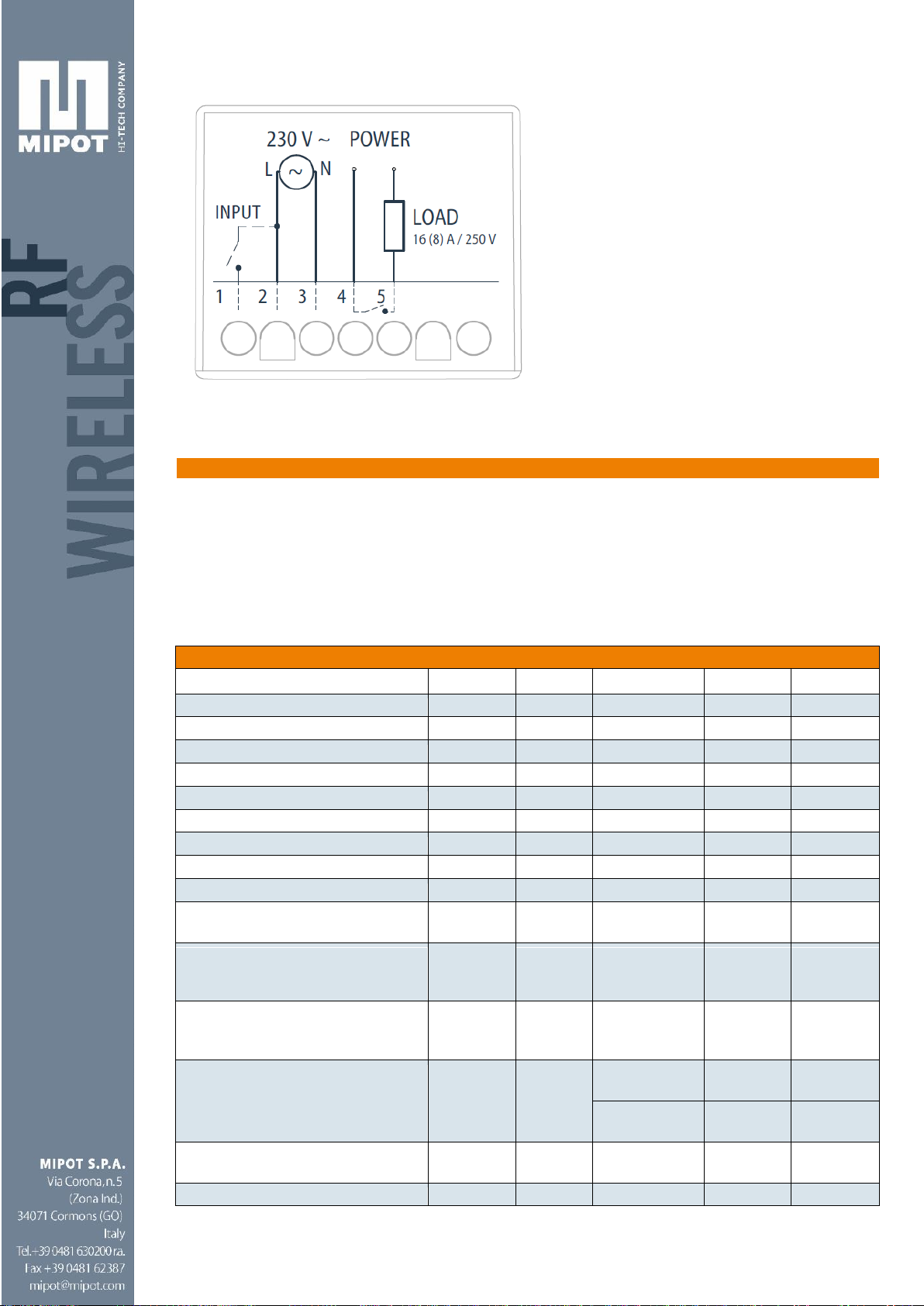
The receiver has been developed to control single-phase electric devices such
as lamps or motors not exceeding the maximum specified ratings, any other use
is prohibited.
The product is under dangerous electrical voltage.
Do not open the product: no user serviceable part inside. Internal parts are under
dangerous voltage even after disconnection from mains.
All connections must be made in the absence of voltage.
The device must not be used as disconnecting switch for live circuits: the
opening of the output does not ensure in any way the absence of voltage on the
controlled loads!
If you open the local input during a voltage drop, at voltage recovery the output
will be still active and under potentially fatal voltage!
Prior to work on any loads controlled by the product, and in general on any
connection upstream and downstream the product, you need to disconnect
power to the entire electrical system where the product is connected!
The installation of the device and the connected equipment should be performed
by qualified personnel only, in compliance with current regulations and with this
document; non-compliant installation can lead to serious danger.
The product is intended to operate only within junction boxes or electrical socket
boxes thus its casing does not have any degree of protection against ingress of
liquids and only a basic protection against contact with solids (IP20). It is strictly
forbidden to use the product in other than its intended use.
Do not open or drill the plastic casing of the product, the underlying circuits are
live; do not cut or strip the wire antenna since it is under line voltage.
INSTALLATION
The controls (buttons or switches) and the connecting cables must have
adequate insulation characteristics for use in electrical systems with an
operating voltage of at least 300V AC
The device does not offer protection against overloads or short circuits on the
outputs, it is therefore necessary to provide adequate protection to the loads
installed (fuse or circuit breaker) on the power line.
The power supply lines must be protected by means of a circuit breaker (2P or

Rev. 2.3
Mipot S.p.A. reserves the right to modify the specifications without notice
Page 5 of 17
1P + N, Type B, rated current not exceeding 16A, breaking capacity not less than
6 kA, with overvoltage category III or contact gap greater than or equal to 3.5
mm) with differential protection (2P or 1P + N, rated current of at least 16A, Idn =
30mA, for type B differential currents) ensuring the omnipolar sectioning from
the mains in case of failure (provided indications refer to a typical installation in
residential environments; the installation of the devices, the layout and size of
the lines must be made by qualified personnel, we cannot accept responsibility
for damage to persons or property due to installation not in accordance with
applicable regulations and product specifications).
If the switching device is not close to the equipment you must have add another
breaker device or a locking system to prevent the unauthorized connection.
Do not install the receiver in sections of SELV system plant (e.g. bell circuits,
video, 12/24V lights, LED circuits, etc.).
The maximum length of the local input cables (terminal 1, see below) is 4 meters.
SCHEMATIC WIRING INDICATIONS:
Schematic 1. Schematic indications for the control of one load
Warning: the maximum length of the cable connected to the local input is 4 meters.
Make sure the connections are correct before powering up the module: incorrect
connection may damage the equipment and cause danger to personal safety.
1 2 3 4 5
Line
230 Vac
Neutral
P1 key
DL1 led
Local inputs:
- 1 switches
or
- 1 button
Max cable
length: 4
1 resistive load
250 Vac
4000 VA Max

Rev. 2.3
Mipot S.p.A. reserves the right to modify the specifications without notice
Page 6 of 17
CHARACTERISTIC OF RECEIVABLE FRAMES
The receiver is capable to correctly recognize remote controls with either FIXED CODE or
HCS (ROLLING CODE). The characteristics of valid FIX codes are:
-Base time: from 300 us to 1 ms
-Start bit: high for one base time duration
-Format:
0 bit: low signal for one base time duration followed by high signal for two base
times
1 bit: low signal for two base times duration followed by high signal for one base
time
-Bit Amount: from 12 to 40
-Minimum number of decoded frames: 2
“One” bit “Zero” bit
In case of fixed codes, the base time is measured during the learning process; the command
is executed when a received frame has a base time within +/-10% of the measured value.
Note: if you learn rolling code remote controls, you cannot learn fixed code remote
controls, and vice versa unless you erase the remote controls memory before.
Simultaneous reception of fixed and HCS remote controls is not possible.

Rev. 2.3
Mipot S.p.A. reserves the right to modify the specifications without notice
Page 7 of 17
USER MANUAL
1. DESCRIPTION
This receiver has been developed for recessed installation into wall outlets and permits the
control of devices remotely or locally (e.g. via a control panel or standard wall-recessed
switches) with a maximum 16A load. It is directly powered from the 230 Vac mains. For
remote operation, you can use any ASK or OOK remote control operating at 433.92 MHz,
FIXED or ROLLING code.
1.1General Characteristics
Power supply: 230Vac 50-60Hz
Operating frequency of radio receiver: 433.92 MHz
Modulation: ASK/OOK
1 relay output: maximum current 16 Ampere.Examples:
- Pmax (230Vac) = 3680 VA per cosφ=1,
- Pmax (230Vac = (3680 x cosφ) VA per cosφ < 1
- Pmax (115Vac) = 1840 VA per cosφ =1,
- Pmax (115Vac) = (1840 x cosφ) VA per cosφ < 1
1 local input
3 output control modes:
- monostable
- bistable (factory default)
- timed
Key for learning / configuration
Led during learning / configuration
Up to 30 storable remote-controls (the number is depending upon the coding used)
1.2I/O terminal board
2 Description of I/O terminal board connections:
Terminal 1: input (cabled) for local control of relay
Terminal 2: power supply input (line/positive)
Terminal 3: power supply input (neutral/negative)
Terminal 4: relay common
Terminal 5: relay output

Rev. 2.3
Mipot S.p.A. reserves the right to modify the specifications without notice
Page 8 of 17
2. OPERATION
2.1.Remote input operation (remote control)
Pressing one of the buttons of the memory stored remote controls enables or disables the
output of the receiver according to the functions described in paragraph 2.3 Functions
Definitions.
The remote controls buttons are learned individually (you cannot learn a whole remote button
set just by learning one of its transmission keys). The remote controls are learned according
to the procedure described in paragraph 0

Rev. 2.3
Mipot S.p.A. reserves the right to modify the specifications without notice
Page 9 of 17
RADIO PROCEDURES.
When you turn on the device, it informs the installer about the presence of previously stored
remote controls:
-One LED flash of ½ second if there is at least one stored remote
-Two LED flashes if there are no remote controls stored
2.2. Local input operation (cabled)
The output functions of the device are the same as the previous case, besides that the
command is not given via radio, but from a hardwired input.
The entrance is located on the local terminal 1 and the change of state occurs when it is
connected / disconnected to/from the line.
Standard recessed devices (buttons or switches) can be connected to the local input (i.e.
between terminal 1 and LINE).
To enable these two options the following operating logic is implemented:
-If the contact is kept closed for less than one second (or when using a standard
button), the command is executed only at the contact closing
-If the contact is kept closed for a longer time (i.e. when using a standard switch), the
command is executed at both the closing and the reopening of the contact.

Rev. 2.3
Mipot S.p.A. reserves the right to modify the specifications without notice
Page 10 of 17
2.3Functions Definitions
Device can be programmed to execute the following functions:
FUNCTIONS
Function
Description
Monostable
The selected output is activated when pressing any one of the
corresponding buttons on the remote control.
If the output is already active (for example, during the corresponding
activation of the local command), a subsequent activation command
(e.g. pressing the corresponding button on the remote control) is
ignored.
In case of voltage drop, when power returns the mini receiver
maintains the state of the outputs (if the local input status is not
changed during the power failure).
Caution: if the output was active before the voltage dip,
at voltage recovery the output will remain in any case
active for a fraction of a second!
Bistable
The outputs are controlled as follows:
- First press of the button: the stored output on the corresponding
button is activated
- Second press of the remote control: the output is disabled
In addition, when the local switch is closed, and its output is active, if
you press the corresponding button on the remote control the output
turns off, and when you reopen the switch the output is activated
again.
Finally, the bistable is the default mode in which receivers come out of
the factory, it is automatically reset after erasing the memory.
In case of voltage drop, when power returns the mini receiver
maintains the state of the outputs (if the local input status is not
changed during the power failure).
Caution: if the output was active before the voltage dip,
at voltage recovery the output will remain in any case
active for a fraction of a second!
Time
In this mode, the selected output is switched at the pressure of any of
the corresponding buttons o the remote control and remains active for
a period of time (timeout) previously stored in the device. The output
can be turned off when you press the button after a minimum time of 5
seconds.
The output can be controlled similarly also through the local input.
(E.g.: if the switch is closed, the output is turned on for the set time,
then it turns off. If you then open the switch, the output is activated and
the timer starts again. Changing the status of the switch is equivalent
to pressing the button: it causes the deactivation of the output, after a
minimum time of 5 seconds).
In case of voltage drop, when power returns the mini receiver
maintains the outputs OFF.
Caution: if the output was active before the voltage dip, at
voltage recovery the output will remain in any case active
for a fraction of a second!

Rev. 2.3
Mipot S.p.A. reserves the right to modify the specifications without notice
Page 11 of 17
The functions described above apply to all remotes stored in memory. You cannot assign
different functions to different remote controls.
The change of function is as described in paragraph 3. PROCEDURES - OUTPUT
FUNCTIONS PROGRAMMING.
A change of function does not erase the memory of stored remote controls.
3. PROCEDURES
MEMORY RESET
Phase
Description
Example
1
Press and hold the programming button of the MINI-
RX until the LED on the receiver blinks twice shortly.
> 3s
x 2
2
After about 1 second by the release of the button, the
LED on the receiver emits five flashes.
x 5
3
Press the button of the receiver during the third flash.
x 3
4
If cancellation is successful the receiver will emit 3
short flashes .
The memory erasure resets the device to factory
default settings:
-No remote control stored
-Bistable mode
-Default timings (see paragraph
“TIMEOUT PROGRAMMING”)
x 3
5
End

Rev. 2.3
Mipot S.p.A. reserves the right to modify the specifications without notice
Page 12 of 17
REMOTE CONTROLS MEMORY ERASURE
Phase
Description
Example
1
Press and hold the programming button of the MINI-
RX until the LED on the receiver blinks twice shortly.
> 3s
x 2
2
After about 1 second by the release of the button, the
LED on the receiver emits five flashes.
x 5
3
Press the button of the receiver during the fourth
flash.
x 4
4
If cancellation is successful the receiver will emit 5
short flashes.
The remote controls memory erasure does not
reset the outputs settings.
x 5
5
End
SINGLE REMOTE CONTROL ERASURE
Phase
Description
Example
1
Press and hold the programming button of the MINI-
RX until the LED on the receiver blinks twice shortly.
> 3s
x 2
2
After about 1 second by the release of the button, the
LED on the receiver emits five flashes.
x 5
3
Press the button of the receiver during the fifth flash.
x 5
4
Push the button on the remote control you want to
erase.
5
If cancellation is successful the receiver will emit 5
short flashes.
The remote controls memory erasure does not
reset the outputs settings.
x 5
6
To erase another transmitter, repeat step 4.
7
To complete the procedure to wait for the 10 seconds
time-out.
8
End

Rev. 2.3
Mipot S.p.A. reserves the right to modify the specifications without notice
Page 13 of 17
OUTPUT FUNCTIONS PROGRAMMING
Phase
Description
Example
1
Shortly press the programming button of the MINI-RX
3 times. The LED on the receiver will blink 3 times
every 2 seconds.
x 3
x 3
2
Hold down the programming button of the MINI-RX for
more than 3 seconds. The LED on the receiver will
perform another blink.
> 3s
x 1
3
Press the programming button a number of times
equal to the mode you want to program:
1 pressure -> Monostable
2 pressures -> Bistable
3 pressures -> Timed
4 pressures -> Roll back to Monostable
The system will notify through the LED the selection
the user just made, with a number of (fast) blinks
equal to the selected function, repeated every 2
seconds
x n
x n
4
To store the selected mode, press and hold the
programming button of the MINI-RX for more than 3
seconds. The LED on the receiver will perform another
blink.
Output function change does not erase the stored
remotes.
> 3s
x 1
5
End

Rev. 2.3
Mipot S.p.A. reserves the right to modify the specifications without notice
Page 14 of 17
TIMEOUT PROGRAMMING:
Phase
Description
Example
1
Shortly press the programming button of the MINI-RX.
The LED on the receiver will blink every 2 seconds.
x 1
x 1
2
Hold down the programming button of the MINI-RX for
more than 3 seconds. The LED on the receiver will
perform another blink.
> 3s
x 1
3
Press the programming button a number of times
equal to the hours of activation you want to program:
1 pressure -> 0 Hour
2 pressures -> 1 Hours
…
10 pressures -> 9 Hours
The receiver will blink 2 times at each button pressure.
x n
x 2
4
Confirm the hours of operation by holding down the
button programming of the MINI-RX for more than 3
seconds. The receiver will perform a (long) blink.
> 3s
x 1
5
Press the programming button a number of times
equal to the minutes of activation you want to
program:
1 pressure -> 0 minute
2 pressures -> 1 minutes
…
60 pressures -> 59 minutes
The receiver will blink 3 times at each button pressure.
x n
x 3
6
Confirm the minutes of operation by holding down the
button programming of the MINI-RX for more than 3
seconds. The receiver will perform a (long) blink.
> 3s
x 1
7
Press the programming button a number of times
equal to the seconds of activation you want to
program:
1 pressure -> 1 second
2 pressures -> 2 seconds
…
59 pressures -> 59 seconds
The receiver will blink 4 times at each button pressure.
x n
x 4

Rev. 2.3
Mipot S.p.A. reserves the right to modify the specifications without notice
Page 15 of 17
TIMEOUT PROGRAMMING:
Phase
Description
Example
(NOTE: If you try to set a time of 0 seconds, the MINI
RX will set a default time of 60 seconds).
8
Confirm the seconds of operation by holding down the
button programming of the MINI-RX for more than 3
seconds. The receiver will perform a (long) blink.
If timeout settings are not confirmed, the
previously stored timeout is maintained.
> 3s
x 1
9
End

Rev. 2.3
Mipot S.p.A. reserves the right to modify the specifications without notice
Page 16 of 17
4. RADIO PROCEDURES
LEARNING THE FIRST REMOTE CONTROL OR ADDITIONAL REMOTES
Phase
Description
Example
1
Shortly press twice the programming button of the
MINI-RX. The LED on the receiver will perform 2 blinks
every 2 seconds.
x 2
x 2
2
Hold down the programming button of the MINI-RX for
more than 3 seconds. The LED on the receiver will
perform another blink.
> 3s
x 1
3
Press the programming button a number of times equal
to the output you want to program:
1 pressure -> output 1
2 pressures -> output 2
3 pressures -> roll back to output 1
The system will notify the user the selection just made
with a number of LED blinks (fast) equal to the selected
output, repeated every 2 seconds.
x n
x n
4
Press the button on the remote that you want to store.
If the current pair button-remote is not stored yet, the
receiver saves it in memory performing 2 long LED
blinks and buzzer beeps.
On the other hand, if the memory contains this
information already, 2 short LED blinks and buzzer
beeps will occur.
NEW
x 2
PRESENT
x 5
5
To learn another remote (or another button), repeat
steps 3 and 4.
6
To complete the remotes learning process, wait for the
programming timeout that will be indicated by a long
beep and a long blink of the LED.
x 1
Note
If the memory is full, the receiver’s LED will perform 10
blinks.
x 10
7
End

Rev. 2.3
Mipot S.p.A. reserves the right to modify the specifications without notice
Page 17 of 17
DECLARATION OF CONFORMITY:
We, MIPOT S.p.a.
Via Corona, 5
34071 - Cormons (GO) - Italy
declare that the product 33000148MIP, 16A MINI RX complies with the essential
requirements and other relevant provisions of Directives:
2014/53/EU (RED Directive)
Directive 2011/65/EU (RoHS)
The declaration of conformity can be downloaded at http://www.mipot.com/en/rf-wireless-
products/16a-wireless-switch-control-rx-33000148mip/.
Table of contents