CHC i80 GNSS User manual

I80
Maintenance
Manual

- 1 -
Contents
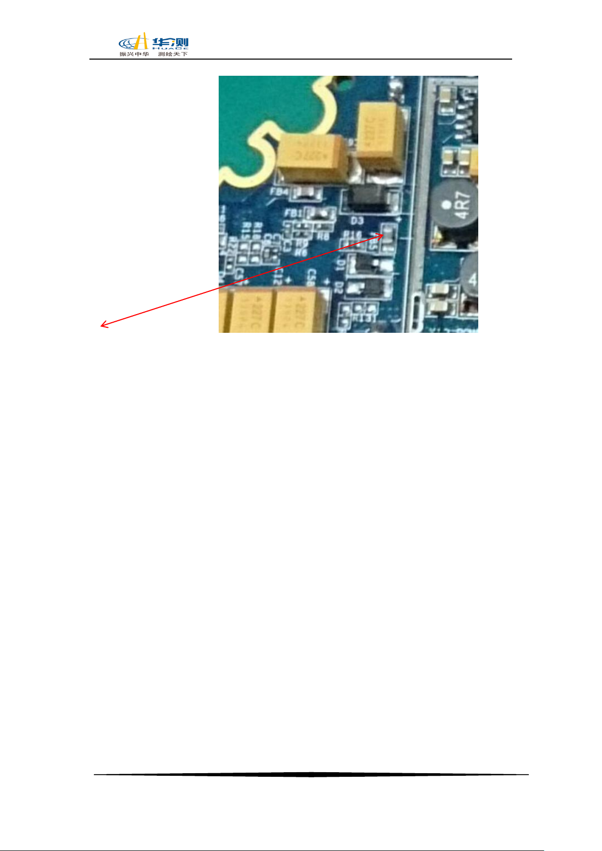
1:Power on/off problem................................................................................................................- 2 -
1.1 When insert battery or use 12 V external power supply, the power LED is off...............- 2 -
1.2:Auto power off problem:...........................................................................................- 3 -
1.3:LED flash Error:..........................................................................................................- 4 -
2:Communication Problem ........................................................................................................- 4 -
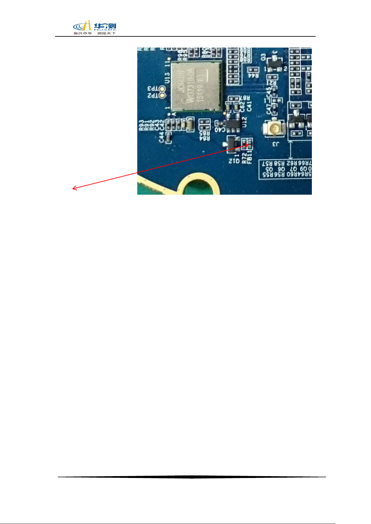
2.1:BT/ Wi-Fi problem ........................................................................................................- 4 -
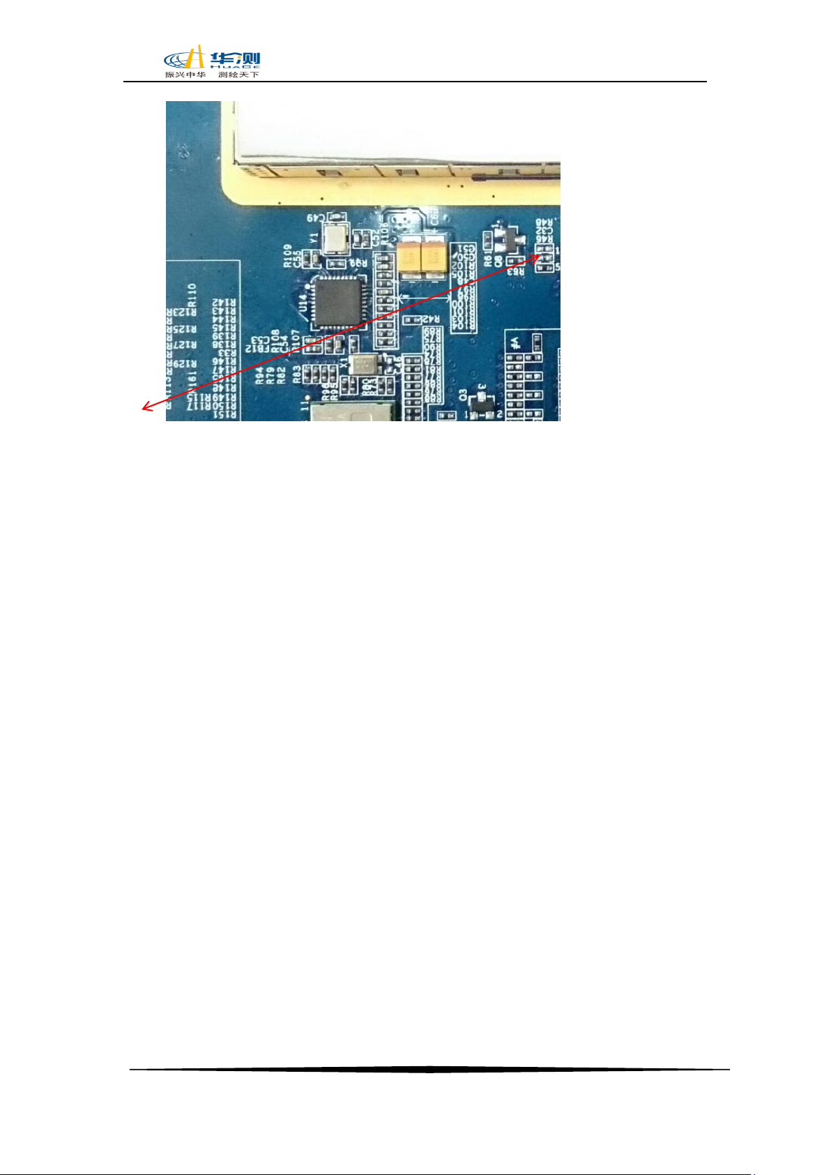
2.2:Com port/USB port problem........................................................................................- 5 -
2.3: Internal storage problem ...............................................................................................- 6 -
3: Searching satellites problem .....................................................................................................- 8 -
3.1:Not searching satellites ................................................................................................- 8 -
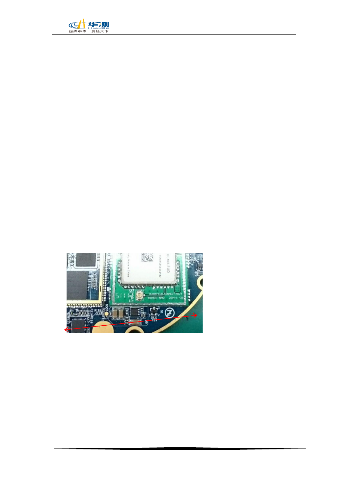
4:Network problem.......................................................................................................................- 9 -
4.1 The receiver cannot dial on, showing offline on the webpage, Network module
continuously resetting...........................................................................................................- 9 -
5: Radio problem........................................................................................................................ - 10 -
5.1:.................................................................................................................................. - 10 -
Cannot get the radio signal frequency setting not successful ........................................... - 10 -
5.2:Radio signal not stable .............................................................................................. - 10 -
6:Shell problem:........................................................................................................................ - 11 -
6.1 Battery cover problem, Battery cover cannot shut, battery connector broken........... - 11 -
7:Tilt problem............................................................................................................................. - 12 -
7.1 Cannot detect the tilt nodule cannot proceed the tilt alignment................................ - 12 -

- 2 -
Repair & Solution
1: Power on/off problem
1.1 When insert battery or use 12 V external power supply, the power LED
is off.
Detection Method&Solution:
(1)Detect the input voltage of power supply. The external power supply
should be more than 12 V, the battery should be 6.9V to 8.3V.
If the detecting voltage is less than the minimum value, please replace the power
supply or battery.
(2)Detect the power button works well or not. The power button should
have elasticity and when you press the button, it should be a spring back voice.
If not, please replace the button panel.
Detect the spring in battery cabin. The spring should not have shape change and
spring contact with good flexibility and elasticity.
If not, please replace spring.
(3)Detect the FPC flexible conduction band. Separate the receiver to check
the band correctly install or not.
If not, please re-install or replace the FPC flexible conduction band.
Detect the LED light. Sometimes the LED light out caused misjudge receiver cannot
be power on.
If so, please replace the button panel.
(4)Detect the mainboard. Detect the FB5 voltage and compare it with the
voltage of power supply.
If the voltage is the same, please replace the mainboard.
(5) Replace the front interface panel.
(6) Replace the mainboard.

- 3 -
FB5 point out as picture:
1.2:Auto power off problem:
Fault description: When use the power supply, the receiver will auto power off.
Detection Method&Solution:
(1)Detect the serial FPC flexible PCB. Separate the receiver to check the band
correctly install or not.
If not, please re-install the FPC flexible PCB.
(2)Detect the battery voltage. The battery should be 6.9V to 8.3V.
If not, please replace the battery.
(3)Detect mainboard parts to check there is any insufficient solder caused short
circuit.
If so, please replace the mainboard.
(4)Core board faults caused program error.
If so, please replace the mainboard.
(5)

- 4 -
1.3:LED flash Error:
Fault description:
After power on the receiver, the LED light flashes abnormal.
Detection Method&Solution:
(1)Indicator light line fault.
If so, please replace the button panel.
(2)Mainboard error caused lights abnormal when power on.
If so, please replace the mainboard.
(3)i80 flexible circuit board is not good and the LDE circuit does not make sense.
If so, please replace the FPC flexible circuit board.
2:Communication Problem
2.1:BT/ Wi-Fi problem
Fault description:
After power on the receiver, handheld cannot search Bluetooth or Wi-Fi of the
receiver.
Detection Method&Solution:
(1)Bluetooth and Wi-Fi antenna assemble improper.
If so, please reassemble or replace the Bluetooth and Wi-Fi antenna.,Wi-Fi
(2)Bluetooth and Wi-Fi module failure. Please detect the FB11 on the mainboard
and the exact voltage from FB11 is 3.3V.
If cannot detect the voltage, please replace the mainboard.,Wi-Fi
(3)Firmware problem caused receiver Bluetooth and Wi-Fi abnormal.
If so, please update the receiver firmware.

- 5 -
FB11 as picture attached:
2.2:Com port/USB port problem
Fault description:
The receiver cannot make the connection to the PC with the serial cable.
Detection Method &Solution:
(1)The serial cable has some problem.
If so, please replace another serial cable to have a try.
(2)Detect the serial FPC flexible circuit board. Separate the receiver to check the
band correctly install or not.
If not, please re-install or replace the FPC flexible PCB.
(3)The core board chip has fault. When the power supply, the C60 capacitance
voltage should be 5V. If not, please replace the mainboard.

- 6 -
C60:
The Arrow point out the C60
2.3: Internal storage problem
Fault description:
The memory disk cannot be read when the receiver connected with the PC.
Detection Method&Solution:
(1)The USB data cable meets some problem and it also cannot connect with other
i80.
Please replace the USB data cable and have a try.
(2) PFC flexible circuit board faults.
If so, please re-install or replace the FPC flexible circuit board.
(3) The flash memory chip faults. Please detect voltage of FB13 when the power
supply and the common valve should be 3.3 V.

- 7 -
If not, please replace the mainboard.
(
FB13:
The arrow point out the FB13

- 8 -
3: Searching satellites problem
3.1:Not searching satellites
Fault description:
After power on the receiver cannot search the satellites
Detection Method&Solution:
(1)GPS antenna damage, If yes please replace the antenna
(2) Receiver OEM board problem, if the OEM board cannot reset normally, no output
voltage, or OEM board register code lost, please reset the OEM board first and then
check the OEM board output voltage, the normal OEM board output voltage is
3.3V,or Re-register the OEM board.
(3) OEM board burned or other hardware problem, if yes please replace the OEM
board.

- 9 -
4:Network problem
4.1 The receiver cannot dial on, showing offline on the webpage, Network
module continuously resetting.
Detection Method&Solution:
(1)Sim card error, if yes please replace a sim card
(2)Sim Card slot problem, if yes please replace a sim card slot
(3)GPRS module problem, please detect the voltage of the GPRS module, the normal
C5 output voltage is 4V, otherwise please replace the mainboard.
(4)Mainboard communication problem cannot get the sim card parameters, please
replace the mainboard.
(5) Signal strength low, if yes please replace the GPRS attached antenna..
(6) Parameters setting error Please input the right parameters
C5:
The arrow point out C5

- 10 -
5: Radio problem
5.1:
Cannot get the radio signal frequency setting not successful
In rover radio mode, it cannot get the radio signal, Radio LED didn’t flash.
Detection Method&Solution:
(1) Wrong settings if yes check all the settings and set the right parameters
(2) Radio module problem(please check the power supply voltage
R17:3.3V/R15:4V/R16:5V/R18:9V)if the power voltage is not correct please replace
the radio module
(3)Radio module connect cable problem if yes, please replace the TNC based cable.
(4)Radio module converter board problem, if yes please replace the converter board
(5)check whether can set the radio frequency if no, please replace the converter
board.
The arrow point out R17:3.3V/R15:4V/R16:5V/R18:9V
R17:3.3v/R15:4v/R16:5v/R18:9v as the picture attached:
5.2:Radio signal not stable
Fault description:

- 11 -
The Radio signal not stable, Radio working distance short
Detection Method &Solution:
(1)Radio module broken if yes please replace the radio module
(2)Rod antenna attenuation, if yes please replace the antenna.
(3)Radio module connect cable problem, if yes please replace the mainboard
6:Shell problem:
6.1 Battery cover problem, Battery cover cannot shut, battery connector
broken.
Detection Method &Solution:
(1) Battery cover broken, please replace the battery cover.
(2) Battery connector broken please replace the

- 12 -
7:Tilt problem
7.1 Cannot detect the tilt nodule cannot proceed the tilt alignment.
Detection Method&Solution:
(1) Tilt module broken, it cannot work, cannot alignment if yes please replace the
mainboard.
(2) Receiver register code overdue cause the tilt module not work if yes please
re-register the receiver.
(3) Mainboard power supply error please measure the voltage FB8 standard voltage
3.3V, if the voltage not correct, the power supply have some problem, please replace
the mainboard
FB8:
Other manuals for i80 GNSS
13
Table of contents
Other CHC Receiver manuals
Popular Receiver manuals by other brands

Denon
Denon AVR-985 operating instructions

DS18
DS18 DDX10.5AD owner's manual

Harman Kardon
Harman Kardon AVR 139/230 Service manual

THOMSON
THOMSON DPL915VD - MUSICMATCH SOFTWARE manual

SoundMax
SoundMax SM-RD2122UB instruction manual

Harman Kardon
Harman Kardon Stratophonic SR300B Installation and operation manual