Mircom DTC-300A User manual

. . . . . .
. . ... .. .. . . . . . .. . .
. . . . . . . ... . .. . . .. . .
. . .... . . . . .. . . .! . "... . . . . .. ##.
© Mircom 2005
Printed in Canada
Subject to change without prior notice
. . . .. ... . . .. . .
DTC-300A
Digital Transmitter Communicator
LT-889 Rev.1
October 2006
Installation and Operation Manual
Advanced Life Safety Solutions Advanced Life Safety Solutions
U.S.A.
60 Industrial Parkway
Cheektowaga, NY 14227
Tel: 1-888-660-4655 Fax: 1-888-660-4113
Asn
oi
t
u
l
o
S
y
te
f
aS
e
f
i
L
de
c
n
av
d
A
00
3
-C
TD
R
E
T
A
C
I
N
U
M
M
O
C
R
E
T
T
I
MS
N
AR
T L
A
TI
G
I
D
NO
R
E
W
O
P


DTC-300A DACT Dialer Installation and Operation Instructions
i
Contents
Industry Canada and FCC Notice ........................................................................................... 1
Introduction and Features....................................................................................................... 2
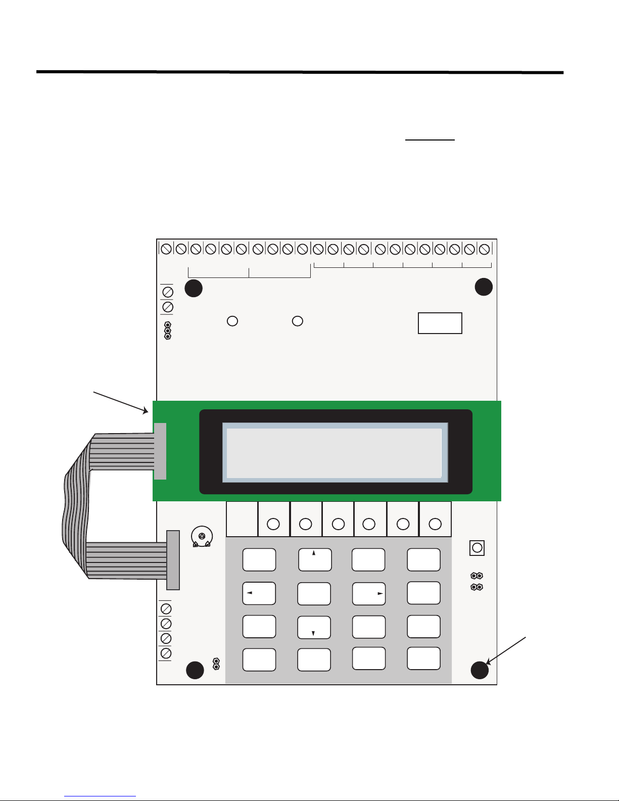
Mechanical Installation and Dimensions ............................................................................... 3
Connections and Settings....................................................................................................... 4
DTC-300A MAIN BOARD ..................................................................................................... 4
Field Wiring............................................................................................................................... 6
DTC-300A MAIN BOARD TELEPHONE WIRING ................................................................ 6
Field Wiring (continued) .......................................................................................................... 7
DTC-300A MAIN BOARD INPUT ZONE WIRING ................................................................ 7
TROUBLE OUTPUT WIRING............................................................................................... 8
POWER SUPPLY WIRING................................................................................................... 9
Power Up Procedures.............................................................................................................. 9
Basic Operation and Supervision........................................................................................... 10
Configuration Set-up ............................................................................................................... 10
CONFIGURATION VIA ON-BOARD KEYPAD ..................................................................... 10
CONFIGURATION VIA UIMA AND COMPUTER(LOCAL):.................................................. 10
CONFIGURATION VIA MODEM AND COMPUTER(REMOTE): ......................................... 11
Keypad Configuration & Operation ........................................................................................ 12
Entering the Passcode.......................................................................................................... 12
Command Menu ................................................................................................................... 13
1.View Event Log (Command-Menu).................................................................................... 13
2. Clear Event Log (Command-Menu) .................................................................................. 14
3. Test Dialer (Command-Menu) .......................................................................................... 15
4. Config Info (Command-Menu) .......................................................................................... 17
5. Version Info....................................................................................................................... 17
6. Set Time (Command-Menu) ............................................................................................. 17
7. Set Password (Command-Menu)...................................................................................... 18
8. Default Config (Command-Menu) ..................................................................................... 19
9. Dialer Config (Command-Menu) ....................................................................................... 19
10. Input Config..................................................................................................................... 24
11. Exit .................................................................................................................................. 24
Compatible Fire Alarm Control Panels .................................................................................. 27
Compatible Receivers.............................................................................................................. 27
Specifications........................................................................................................................... 28
Battery Calculations ................................................................................................................ 28
Warranty & Warning Information............................................................................................ 29
Warning Please Read Carefully............................................................................................ 29
Limited Warranty................................................................................................................... 31
Warranty Procedure.............................................................................................................. 31
Disclaimer of Warranties....................................................................................................... 31
Out of Warranty Repairs ....................................................................................................... 32

ii
Contents

DTC-300A DACT Dialer Installation and Operation Instructions
1
Industry Canada and FCC Notice
Notice for all DTC-300A Sold in the U.S.A.
Mircom's DTC-300A Digital Communicator described in this manual is listed by Underwriters Laboratories Inc.
(ULI) under Standard 864 (Control Units for Fire Protective Signalling Systems). These Communicators comply with
the National Fire Protection Association (NFPA) performance requirements for DACTs and should be installed in
accordance with NFPA 72 Chapter 4 (Supervising Station Fire Alarm System). These Communicators should be
installed in accordance with this manual; the National Electrical Code (NFPA 70); and/or the local Authority Having
Jurisdiction (AHJ).
FCC Notice
This equipment complies with the Federal Communications Commission (FCC) rules and regulations governing
telephone equipment and the Technical Requirements for Connection to the Telephone Network published by the
industry’s Administrative Council for Terminal Attachments (ACTA). On the door of this equipment is a label that
contains, among other information, a product identifier in the format US:XXXXXXXXDTC-300A. If requested, this
number must be provided to the telephone company. This equipment is capable of seizing the line. This capability is
provided in the hardware.
The Ringer Equivalence Number (REN) assigned to each terminal device provides an indication of the maximum
number of devices that may be connected to a telephone line. Excessive REN’s on a telephone line may result in
the devices not ringing in response to an incoming call. In most, but not all areas, the sum of REN’s should not
exceed five (5.0). To be certain of the number of devices that may be connected to a line, as determined by the
total REN’s contact the local telephone company. The REN for this product is X.X.
Telephone Company Procedures: The goal of the telephone company is to provide you with the best service it
can. In order to do this, it may occasionally be necessary for them to make changes in their equipment, operations
or procedures. If these changes might affect your service or the operation of your equipment, the telephone
company will give you notice, in writing, to allow you to make any changes necessary to maintain uninterrupted
service.
In certain circumstances, it may be necessary for the telephone company to request information from you
concerning the equipment which you have connected to your telephone line. Upon request of the telephone
company, provide the FCC registration number and the ringer equivalence number (REN); both of these items are
listed on the equipment label. The sum of all of the REN’s on your telephone lines should be less than five in order
to assure proper service from the telephone company. In some cases, a sum of five may not be usable on a given
line.
If Problems Arise: If any of your telephone equipment is not operating properly, you should immediately remove it
from your telephone line, as it may cause harm to the telephone network. If the telephone company notes a
problem, they may temporarily discontinue service. When practical, they will notify you in advance of this
disconnection. If advance notice is not feasible, you will be notified as soon as possible. When you are notified, you
will be given the opportunity to correct the problem and informed of your right to file a complaint with the FCC.
Contact your telephone company if you have any questions about your phone line. In the event repairs are ever
needed on the Communicator, they should be performed by Mircom Technologies Ltd. or an authorized
representative of Mircom Technologies Ltd. For information contact Mircom Technologies Ltd. at the address and
phone numbers shown on the back page of this document.
Note: The Ringer Equivalence Number (REN) for this product is X.X.

2
Introduction and Features
The DTC-300A is a single board Digital Communicator (DACT) that can connect to any Fire Alarm Control Panel
(FACP). It can transmit Alarm, Supervisory, Waterflow Alarm, Common Trouble, AC power trouble and Battery
Trouble information on two telephone lines to a Digital Alarm Communicator Receiver (DACR).
Features:
• Scans up to 6 configurable input zones. The input zone type may be alarm, waterflow alarm, supervisory,
trouble, AC trouble or Battery trouble.
• Reports to a DACR using Ademco Contact ID or SIA DCS reporting protocols.
• The DTC-300A has the ability of disconnecting the incoming and outgoing calls and capturing the line for
transmission to the DACR.
• Provides telephone line monitoring and reports status via LED indication on-board.
• Provides LED indication for AC Power, Common Trouble, CPU Fail and Ground Fault.
• User configurable locally with on-board keypad and a CFG-300 Configuration Tool or using a UIMA and
computer with serial port or USB. Remotely configurable via a personal computer, modem and telephone line
connection.
• Provides event logs of 500 entries each to save events from local dialer or remote fire alarm panel. These logs
can be reviewed locally with the CFG-300 Configuration Tool or remotely via modem.
• Requires 24V DC filtered or 24V DC Full Wave Rectified (FWR) power supply.

DTC-300A DACT Dialer Installation and Operation Instructions
3
Mechanical Installation and Dimensions
The DTC-300A board is a single PCB assembly. It comes mounted in a 8.25” wide by 9” high by 1.5” deep box.
There are four mounting holes, two at the top and two at the bottom, see Figure 1 below for mounting hole location
and backbox dimensions. There are two conduit holes at the top of the box and two conduit holes at the bottom of
the box.
Figure 1: DTC-300A Backbox Dimensions for Mounting
0RXQWLQJ+ROHV[
7 1/2”
9"
1 1/2”
6 5/16"
8 1/4”
&)*&21),*85$7,21 722/
MNO
WXY
*
0
QZ
#
PRS
7
GHI
4
1
TUV
8
JK L
5
9
6
2
ABC
3
DEF
INFO
CANCEL
MENU
EN TER
TOP AND BOTTOM

4
Connections and Settings
DTC-300A MAIN BOARD
There are FOUR jumpers on the DTC-300A for operation/configuration purposes and 8 LEDs for status indication.
Jumper JW1 is used to reset the default passcode. Jumper JW2 is required for configuring the DTC-300A. Jumper
JW3 is used for enabling/disabling Ground Fault detection and JW4 is used to set the Trouble Relay. Refer to
Figure 2 for the location of jumpers, cable connections, pushbutton and LEDs. Table 1 provides a description of the
status LEDs on the DTC-300A and Table 2 provides information on the use of jumpers JW1 to JW4.
Figure 2: DTC-300A Board Layout
(17(5
0(18
&$1&(/
,1)2
$%&
'()
*+, -./ 012
356 789
:;<
4=
/;99;:
@>;A.81
3>;A:0
2-A8@
/<A
2-58
85:1 85:1 <;C1>
;:
6<67(01250$/
021
42
2%3
%/,
42/5",%
/54054
42
2%3
42
#/
42
#/
,INE
2ELAY,INE 2ELAY,INE
,INE
) )
5
52
#/.42!34
!$*534
#&'
#/.&)'52!4)/.4//,
60/7%2
*7
*7
,!-04%34
-/5.4).'
(/,%3&/52
0
4/5)-!
: : : : : :
/54
).
6$#
%/,2%3)34/2
&/242/5",%
/54054
#/.&)'52!",%).054:/.%34%,%0(/.%,).%#/..%#4)/.3
*7
*7
S/DTC-300A Idle
20:00 SUN 2006-10-1

DTC-300A DACT Dialer Installation and Operation Instructions
5
The following table lists all the LEDs located on the DTC-300A board and states the function of each LED.
Table 1: DTC-300A List of LEDs and their Functions
LEDs FUNCTION
Relay Line 1 Located below Line 1 terminal block. When Line 1 relay is energized, this green
LED will illuminate steady.
Relay Line 2 Located below Line 2 terminal block. When Line 2 relay is energized, this green
LED will illuminate steady.
Common Trouble Steady amber for any troubles on the DTC-300A and/or the Fire Alarm panel.
CPU Fail Steady amber for any on board CPU trouble.
Ground Fault Steady amber for any ground faults on the DTC-300A main board.
Line 1 Telephone Line 1 status indicator LED; Red steady when the line is in use, Amber
steady when there is a line fault.
Line 2 Telephone Line 2 status indicator LED; Red steady when the line is in use, Amber
steady when there is a line fault.
Power ON Green LED is ON steady when power is supplied to the board.
The following table lists the user jumpers available on the DTC-300A and their functions.
Table 2: DTC-300A List of Jumpers for Operation and Configuration
JUMPER NUMBER JUMPER FUNCTIONS
JW1
RESET PASSCODE: Default is normally open. TO RESET PASSCODE: Place
jumper here and power down the DTC-300A by disconnecting the 24V power source
or power down the fire alarm panel (AC and Batteries), then power back up to revert to
the default passcode. After the passcode is reset, remove the jumper.
JW2
BLOCK REMOTE CONFIGURATION: Default is normally open to BLOCK remote
configuration via modem, PC with a UIMA converter module or using the LCD and
keypad at the DTC-300A. A trouble is initiated when the jumper is ON showing that
the DTC-300A is in configuration mode. Place jumper here to ALLOW any type of
configuration. Remove jumper once configuration is complete, trouble will restore.
JW3
GROUND FAULT DETECTION: Default has jumper pins normally shorted allowing
ground fault detection on the DTC-300A. Remove this jumper to DISABLE ground
fault detection (Ground Fault LED on the DTC-300A will not operate). The Fire Alarm
Panel Ground Fault is not affected.
JW4
TROUBLE RELAY: Short pins 1 and 2 to select the TROUBLE OUTPUT relay
contacts as normally closed(N.C.) or short pins 2 and 3 to select the TROUBLE
OUTPUT relay contacts as normally open (N.O.). Default has pins 2 and 3 shorted,
check fire alarm panel for proper setting required for the TROUBLE OUTPUT
contacts.

6
Field Wiring
Field Wiring
DTC-300A MAIN BOARD TELEPHONE WIRING
Wire the two telephone lines to RJ31X Connector terminals as shown in Figure 3 below. The DTC-300A telephone
line terminals are located on the top left hand corner of the board. For a cellular or wireless service, use the Line 2
interface connection.
Figure 3: Telephone Line Wiring Diagram
Note: Most Authorities Having Jurisdiction (AHJ) do not allow the connection of premise
telephones. see specifications for more information.
7755
SUHPLVHWHOHSKRQH
,)SHUPLWWHG
7755
/,1( /,1(
3XEOLFVZLWFK
7HOHSKRQHFRPSDQ\
ZLULQJ
7,3
5,1*
7,3
5,1*
5-;
5('
*5((1
*5(<
%52:1
5(6 5(6&2 &2
/LQHLV:LUHGDVVKRZQIRU/LQH
'7&$

DTC-300A DACT Dialer Installation and Operation Instructions
7
Field Wiring (continued)
DTC-300A MAIN BOARD INPUT ZONE WIRING
There are terminals for six input zones. Zones 1 to 6 are configurable. The default zone settings are as follows:
Input zones 1 through 6 can be connected to the form C relay contact outputs of an associated Fire Alarm panel.
These relay outputs show the status of the Fire Alarm panel as Alarm, Supervisory, Waterflow Alarm, Common
Trouble, AC Power Fail Trouble and Battery Trouble. Each input zone is supervised by an 820 ohms End of Line
Resistor or equivalent MP-820R/W which is a resistor on a white or red plate.
Figure 4: DTC-300A Zone Wiring
Table 3: Zone Default Functions
ZONE DEFAULT FUNCTION
Z1 Common Alarm Input
Z2 Common Supervisory Input
Z3 Common Trouble Input
Z4 Waterflow Alarm
Z5 AC Power Trouble Input
Z6 Battery Trouble Input

8
Field Wiring (continued)
Table 4: DTC-300A Zone Wiring Chart
TROUBLE OUTPUT WIRING
The trouble output is wired to a Fire Alarm Trouble Only monitor zone. This is done to monitor the DTC-300A. The
E.O.L resistor required for this zone is to be placed on the terminals marked E.O.L. below the Trouble Output. The
value of the E.O.L. resistor depends on the FACP used. For the Mircom FACP, use 3K9 ohms. The Trouble Output
terminals are dry contacts. Use JW4 to select either normally closed (pins 1 and 2) or normally open (pins 2 and 3).
Figure 5: DTC-300A Trouble Output Wiring.
Wire gauge Maximum wiring run to last device
AWG Feet Meters
22 2990 910
20 4760 1450
18 7560 2300
16 12000 3600
14 19000 5800
12 30400 9200
Notes:
• Maximum loop resistance should not exceed 100 ohms.
• Maximum capacitance of 0.5uF total on each zone.

DTC-300A DACT Dialer Installation and Operation Instructions
9
POWER SUPPLY WIRING
The DTC-300A requires power from a 24V DC regulated or 24V DC FWR supply. Connect to terminals marked 24V
DC IN, positive and negative.
Figure 6: DTC-300A 24V Power Supply Wiring
Use wire gauge for power supply wiring as specified per Table 5 below:
Table 5: Power Supply Wiring Chart
Power Up Procedures
1. The DTC-300A should be securely mounted on a wall. Make sure ground wire is connected.
2. Check that the telephone lines are connected as shown in Figure 3.
3. Connect the CFG-300 Configuration Tool to the U18 connector and place over the mounting studs on the
DTC-300A above the key pad and secure. This CFG-300 Configuration Tool can be removed once
configuration has been completed.
4. Power up the Fire Alarm Panel and the message on the CFG-300 Configuration Tool should be:
Wire gauge Maximum wiring run to last device
AWG Feet Meters
22 2530 770
20 3940 1200
18 5910 1800
S/DTC-300A Idle
00:00 SUN 2006-10-01

10
Basic Operation and Supervision
The DTC-300A is able to supervise up to 6 local configurable input zones. Once the input zone is active (short
condition), the corresponding event with input zone number will be reported to the monitoring station. If the input
zone is open, a corresponding circuit trouble with input zone number will be reported. Each input zone can be
defined as Alarm, Supervisory, Trouble, Waterflow, AC Power Trouble or Battery Trouble.
The DTC-300A is capable of reporting multiple events to a single account number, within a single call session. For
a single event not yet reported, up to 4 retries will be made within a single call attempt. A failure to report to either
or both accounts will generate corresponding events that will be queued for reporting. Once the DTC-300A fails to
report on all telephone lines, it stops retrying, but an Alarm Event, Manual Test or 24 hour Periodic Test will force the
DTC-300A to seize the line and try reporting again. For two regular Telco telephone line connections, the DTC-
300A checks each line operation by reporting the 24 hour periodic test result on Line #1 or Line #2 alternately.
The DTC-300A continuously supervises the state of each of two connected Telco Lines at approximately 1 minute
intervals.The regular line supervision includes DC voltage level validation and dial tone detection. Line supervision
is skipped while (1) the dialer is busy reporting, (2) the modem is working or (3) there is ringing on the line. If the
line supervision fails, a Line #1 or Line #2 Trouble will be reported after a 30 second verification. Once the line has
been restored, a Line Trouble Restore will be reported.
Configuration Set-up
There are 3 ways of configuring the DTC-300A.
1. Locally with the on-board keypad and CFG-300 Configuration Tool.
2. Locally with a Personal Computer via the RS-232 connection, a UIMA and Mircom Software MSW-012.
3. Remotely with a computer, modem, UIMA and Mircom Software MSW-012.
CONFIGURATION VIA ON-BOARD KEYPAD
1. Connect 24V DC power supply and zone inputs from the DTC-300A to the fire alarm panel.
2. Hook up the CFG-300 Configuration Tool ribbon cable to U18 on the DTC-300A board.
3. Hook up the telephone lines and telephone as shown in Figure 3.
4. Power up the fire alarm panel and the message of the CFG-300 Configuration Tool should be:
5. Place jumper on JW2, located in the bottom right hand corner of the DTC-300A board (this will generate a
trouble on the DTC-300A and report this to the receiver). Press Menu on the keypad to enter the configuration
menu and configure the DTC-300A. The following screen will ask for the passcode.
6. Enter the default passcode, 1111. Press Enter.
CONFIGURATION VIA UIMA AND COMPUTER(LOCAL):
1. Set-up UIMA connection: the 10-pin cable connector of UIMA is connected to P2 on DTC-300A board. A serial
cable or USB cable is needed to connect the UIMA to the computer.
2. Place a jumper at JW2 on the DTC-300A board to allow the configuration (a trouble is generated and reported
to the receiver DACR).
S/DTC-300A Idle
00:00 SUN 2006-10-01
Enter Passcode
Passcode:_

DTC-300A DACT Dialer Installation and Operation Instructions
11
3. Start the Mircom Software MSW-012 on the computer to configure the DTC-300A. Follow the instructions of
MSW-012 menu to complete the configuration of the DTC-300A.
4. Remove jumper on JW2 after configuration is finished, otherwise a trouble will occur.
CONFIGURATION VIA MODEM AND COMPUTER(REMOTE):
1. Set-up the modem connection on the computer. Make sure the phone line is working properly.
2. Place a jumper at JW2 on the DTC-300A board to allow the configuration (a trouble is generated and reported
to the receiver DACR).
3. Start the Mircom Software MSW-012 on the computer to configure the DTC-300A. Follow the instructions of
MSW-012 menu to complete the configuration of the DTC-300A.
4. Remove jumper on JW2 after configuration is finished, otherwise a trouble will occur.

12
Keypad Configuration & Operation
The following shows the configuration at the DTC-300A using the keypad and the CFG-300 Configuration Tool. The
Mircom Digital Communicator is configured by connecting the cable of the CFG-300 Configuration Tool to the U18
connector on the DTC-300A Main Board and placing the LCD over the 3 standoffs as shown in Figure 2.
In order to configure the DTC-300A, place a jumper on JW2, remove once configuration is complete otherwise
there will be a trouble.
To access configuration mode press the Menu button on the keypad. The CFG-300 LCD will display the Main
Menu. The keypad on the DTC-300A board and the CFG-300 is shown together in Figure 7,below.
Figure 7: DTC-300A Configuration
Entering the Passcode
The programming section is passcode protected. The following image shows the message that is displayed to enter
the passcode. The minimum number of digits allowed is four and the maximum allowable passcode is ten digits
long; numerical values only. Press the “ENTER” key after entering the passcode. If the passcode is correct, it will
take you to the main command menu. If the passcode is incorrect, the system will ask you to re-enter the passcode.
The system will be exhausted after three retries and will then take you back to the Normal message display. The
default password is 1111.
After you select a feature item by pressing the "ENTER" key, use the "UP" and "DOWN" keys to move
through the different features. Use the "LEFT" and "RIGHT" keys to change the values. To confirm the
changes press the "ENTER" key. To go one level back press the "CANCEL" key.
(17(5
0(18
&$1&(/
,1)2
$%&
'()
*+, -./ 012
356 789
:;<
4=
#/--/.
42/5",%
'2/5.$
&!5,4
#05
&!),
,).% ,).% 0/7%2
/.
6<67(01250$/
021
S/DTC-300A Idle
20:00 SUN 2006-10-1
Enter passcode
_

DTC-300A DACT Dialer Installation and Operation Instructions
13
Command Menu
The main command menu is pictured below. The first line of the LCD will always show “-Command Menu-“, and the
second line displays the different selections. Use the “UP” and “DOWN” keys to move through the menu, and press
the “ENTER” key to make a selection. To exit from the main command menu, press “CANCEL” or select the “Exit”
menu option and then press the “ENTER” key.
1.View Event Log (Command-Menu)
Note: Command Menu feature 9 and 10 can only be accessed if jumper JW2 is placed on the main board,
see Table 1.
Select the type of log to view. Press the
“ENTER” key. The system will then show the
log chosen.
Use this function to select the log to view. Either the local or
remote log. The remote log contains all events associated
with the fire alarm panel. The local log contains all events
associated with the DTC-300A. Each log can hold up to 500
events.
-Command Menu-
1. View Event Log
2. Clear Event Log
3. Test Dialer
4. Config Info
5. Version Info
6. Set Time
7. Set Password
8. Default Config
9. Dialer Config
10. Input Config
11. Exit
-View Event Logs-
1 Remote Log
2 Local Log

14
Keypad Configuration & Operation
Pressing the “INFO” key provides more information about the displayed event. The illustration below provides an
example of how the “INFO” key works.
There are a maximum of 500 recent events saved in the event log. If the number of events goes beyond 500, all
new incoming events will be ignored.
2. Clear Event Log (Command-Menu)
Select the type of log to clear. Press the
“ENTER” key. The system will then confirm
before clearing logs.
Press the “ENTER” key to confirm or the
“CANCEL” key to cancel the operation.
Use this function to clear remote logs, local logs, or both. The
remote log contains all events associated with the fire alarm
panel. The local log contains all events associated with the
DTC-300A. Each log can hold up to 500 events.
of
-Clear Log-
1 Remote Log
2 Local Log
3 All Logs
Clear all the
selected log(s)? Y
Log(s) cleared

DTC-300A DACT Dialer Installation and Operation Instructions
15
3. Test Dialer (Command-Menu)
Dialer Test Messages
The following messages will display during the test processes of Lines #1 and #2. The messages that will appear
depend on the status of the dialer and the test results that are found.
Press Enter to test Line #1. Press Cancel to exit
this menu. For a description of test messages,
see Dialer Test Messages on the following
page.
Press Enter to test Line #2. Press Cancel to exit
this menu. For a description of test messages,
see Dialer Test Messages on the following
page.
This feature flushes all reportable events from
the buffer, clears all dialer troubles and resets
the dialer operation. Press Enter to reset the
dialer. Press Cancel to exit this menu.
The dialer is checking the line for voltage. This
message automatically displays when Manual Test is
selected.
No DC line voltage. The line is dead or no phone line
is connected or the phone line operates at abnormal
voltage.
The dialer is waiting for a dial tone.
This message may indicate a noisy telephone line.
The dial tone was detected and telephone number
dialing is in process.
This message indicates that the dialer failed to send a
DTMF tone.
Waiting for availability of the receiver. The receiver
confirms the availability by sending an Ack tone.
-Dialer Test-
1. L#1 Manual test
2. L#2 Manual test
3. Reset Dialer
1.L#1 Manual test
2.L#2 Manual test
3 Reset Dialer
.
Dialer idle now
No DC Volt
Waiting for Dialtone
Failed: No Dialtone
Dialing Receiver Now
No DTMF tone
Waiting for Acktone

16
Keypad Configuration & Operation
Dialer failed to detect Ack tone. This message
indicates that either the telephone number may be
wrong or the receiver is not available.
Sending events to the receiver.
The dialer is waiting for the Kissoff tone. The Kissoff
tone indicates that the receiver has received the event
reports.
No Kissoff means dialer did not detect Kissoff tone.
The line passed the test; everything is OK.
Failed No Acktone
Reporting Event Now
Waiting for Kissoff
No Kissoff
Passed: Manual test
Other manuals for DTC-300A
1
Table of contents
Other Mircom Cell Phone manuals