9
Note: The relay can drive a load up to 10 amps at 120 VAC
Safe Module Plus Overview
The Safe Module Plus (SMP) is an exclusive device
that speeds and simplies the installation of a Mission
MyDro 150 or 850 RTU. It supports four pulse counting
channels that can be used with rain tipping buckets
or pulse-based ow meters. It provides an intrinsically
safe circuit to a oat so that the state of the oat can be
transmitted by the MyDro RTU for alarm notications
as well as to energize a built-in-relay that is typically
associated with a local buzzer or light for sewer lift
station applications, or service-pump lock-out for clear
well applications.
Note: For legacy (M110, M800) RTU upgrades
that utilize the Wet Well Module, see Appendix A.
NEC Rule 22-704
National Electric Code (NEC)
Rule 22-704 offers comprehensive
criteria for classication of
hazardous locations. Sewer lift
stations are generally considered
Class I, Division I environments
and require corresponding
intrinsically safe apparatus.
Methane (explosive) and
hydrogen sulde (corrosive) are
common vapors present in these
environments.
The oat circuit associated with
the SMP is certied as intrinsically
safe: Class I, Div I, II, III, Groups
D–G.
Chapter 6: Safe Module Plus (PN OP750)
See the specication sheet for
overview and application data
and the UL Control Document
for intrinsically safe application
and installation information.
UL Control Document for
OP-750 Safe Module Plus
SAFETY DESCRIPTION:
The Safety Module Plus apparatus is to be installed in an
Unclassied Location while providing intrinsically safe output for
Class I, Division 1, Groups A, B, C and D Hazardous Locations in
the US and Canada. Additionally for [AEx ia Ga] X in the US and
[Ex ia Ga] IIC X in Canada. The apparatus is intended for use in
ambient temperature range of -20C to 60C.
WARNINGS
OP-750 series must be installed, operated and maintained only
by qualied personnel, in accordance to the relevant national/
international installation standards (e.g. ANSI/ISA RP12.06.01
Installation of Intrinsically Safe System for Hazardous (Classied)
Locations, National Electrical Code NEC ANSI/NFPA 70 Section
504 and 505, Canadian Electrical Code CEC) following the
established installation rules, particular care shall be given to
segregation and clear identication of I.S. conductors from non
I.S. ones.
De-energize power source (turn off power supply voltage) before
plugging or unplugging the terminal block (J4) when oat is
installed in Hazardous Locations or unless area is known to be
nonhazardous.
Warning: Explosion Hazard: to prevent
ignition of ammable or combustible
atmospheres, disconnect power before
servicing or unless area is known to be
nonhazardous.
Danger d’Explosion: pour prévenir une
inammation de l’atmosphère inammable
ou combustible, couper l’alimentation
avant de réparer à moins de savoir que
l’emplacement n’est pas dangereux.
Units must be protected against dirt, dust, extreme mechanical
(e.g. vibration, impact and shock) and thermal stress, and casual
contacts.
If enclosure needs to be cleaned use only a cloth lightly
moistened by a mixture of detergent in water.
Electrostatic Hazard: to avoid electrostatic
hazard, the enclosure must be cleaned only
with a damp or antistatic cloth.
Danger électrostatique: pour éviter le
danger électrostatique, l’enveloppe doit être
nettoyée au moyen d’un chiffon humide ou
antistatique. Any penetration of cleaning
liquid must be avoided to prevent damage
to the unit.
Failure to properly install or use the equipment may risk damage
to the unit or severe personal injury. The unit cannot be repaired
by the end user and must be returned to the manufacturer or his
authorized representative. Any unauthorized modication must be
avoided.
Warning: substitution of components may
impair Intrinsic Safety.
Avertissement: le remplacement des
composants peut dégrader la Sécurité
Intrinsèque.
It is tested for a maximum for AC power supply (Um) of 120 VAC.
Control equipment must not use or generate more than 120 V rms
or dc with respect to earth.
Selected intrinsically safe equipment must be third party listed
as intrinsically safe for the application, and have intrinsically safe
entity parameters conforming with Table 1 (see next page).
SPECIAL CONDITIONS FOR SAFE USE
The device does not meet the 500V rms dielectric requirement
between the IS circuit and earth.
ASSOCIATEDAPPARATUS
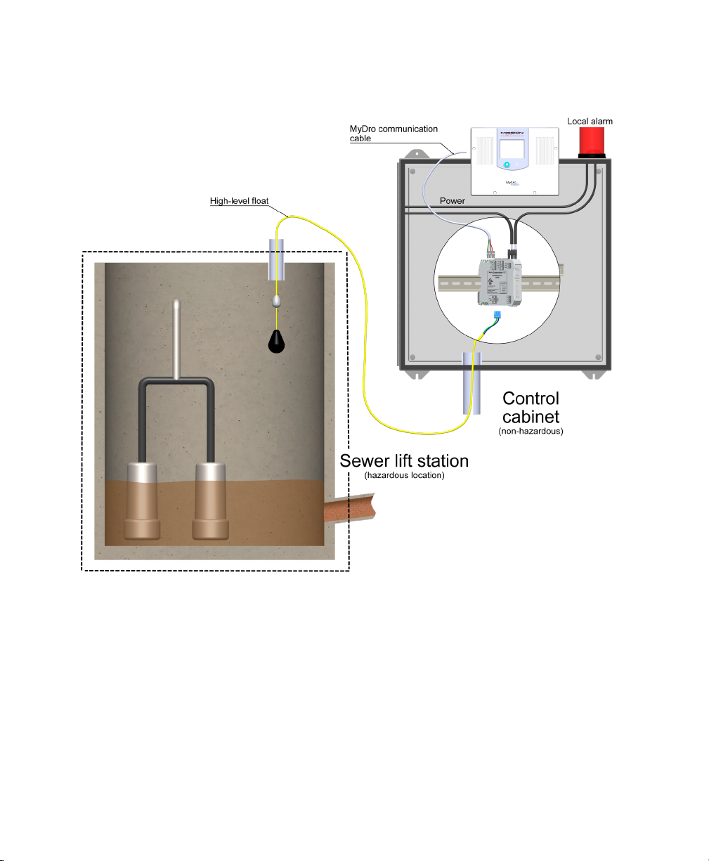
In sewer lift station applications, the high level oat (located in the
sump) including the cable is in a hazardous location. This simple
apparatus as dened and installed in accordance with Article
504.2 and with Article 504.10(D) of the National Electrical Code
(ANSI/NFPA 70), or other local codes, must comply with the entity
parameters described in Table 1 (see next page).
Capacitance and inductance of the eld wiring from the
associated apparatus to the Safe Module Plus shall be calculated
and must be included in the system calculations as shown
in Table 1. Cable capacitance, Ccable, plus intrinsically safe
equipment (oat switch) capacitance, Ci must be less than the
marked capacitance. Likewise, cable inductance plus intrinsically
safe equipment (oat switch) inductance (Li) must be less than the
marked inductance.
Where the cable capacitance and inductance per foot are not
known, the following values shall be used: Ccable = 60 pF/ft. (200
pF/m), Lcable = 0.2 μH/ft (1.0 μH/m.) These calculated maximum
lengths do not allow for any switch capacitance or inductance.
(The cable length must be less than 800 feet not including
allowances for the switch.)
For installations in which both the Ci and Li of the intrinsically
safe apparatus exceeds 1% of the Ca (or Co) and La (or Lo)
parameters of the associated apparatus (excluding the cable),
then 50% of Ca (or Co) and La (or Lo) parameters are applicable
and shall not be exceeded. The reduced capacitance shall not be
greater than 1 μF for Groups C and/or D (IIB and/or IIA), and 600
nF for Groups A and B (IIC).
The values of Ca (or Co) and La (or Lo) determined by this
method shall not be exceeded by the sum of all of Ci plus cable
capacitances and the sum of all of the Li plus cable inductances in
the circuit respectively.
This associated apparatus has not been evaluated for use in
combination with another associated apparatus.
Where multiple circuits extend from the same piece of associated
MyDro Expansion
Safe Module Plus
Intrinsically safe circuit to oat, speeds
installation, and supports pulse inputs
For Hazardous Environments
Most sewer lift stations are considered hazardous locations per the
National Electric Code (NEC Rule 22-704). The MyDro Safe Module
Plus allows the state of a high-level oat (located in the hazardous
location) to be shared with both the local control panel and the Mission
remote terminal unit (RTU) while complying with NEC requirements for
hazardous environments. The oat-sensing circuit is certied for Class I,
Division I (methane) environments typical of sewer lift stations.
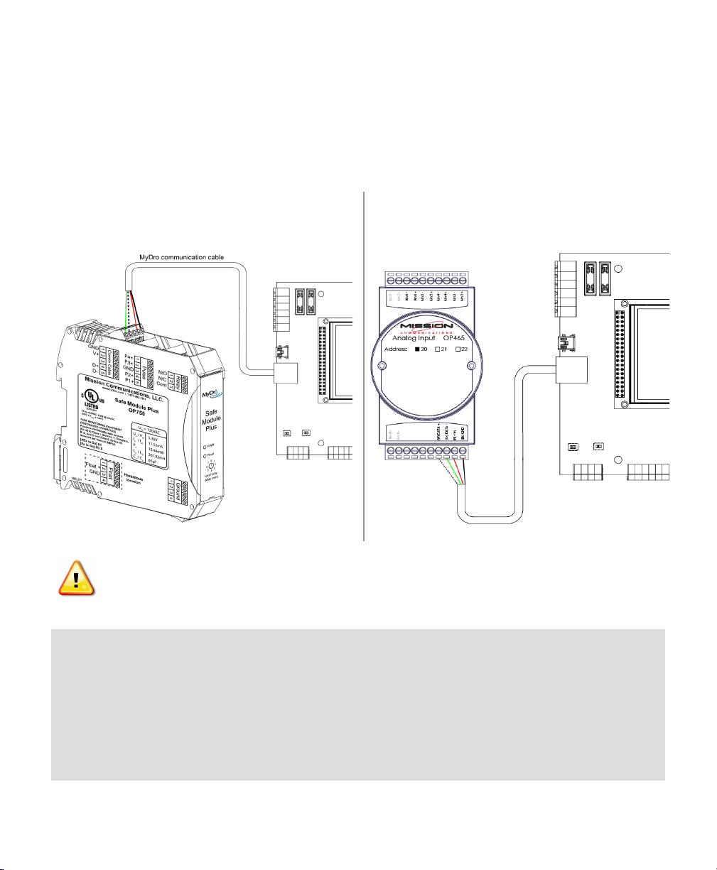
Speeds Installation
The optional module connects to the MyDro 150 or 850 RTU with a
quick-connect communications cable. The cable powers the module and
includes the RS485 communications link between the two components.
The RS485 standard is capable of reliable communications up to 4,000
feet, allowing the module to be located closer to the sensed elements.
The enclosure is compatible with standard DIN rail. Terminals are front-
facing.
High Wet WellAlarms Even When AC Has Failed
High wet well events are reported even when there is no AC power to the
station because of the backup battery associated with MyDro unit.
Relay—Local Alarm
A built-in relay can drive a local alarm light and buzzer based on oat.
Relay—Lock-Out Functions
The relay can be used in specialty applications where safety lock-out
functions are desired. Aselectable debounce (time delay) can be set
for the included relay to avoid short cycling of equipment because of a
bouncing oat. For example, in clean water applications the relay can be
included in the control circuit of a service pump and used to lock-out the
pump before the supply runs dry, as indicated by a normally open (N/O)
low-level oat. The Mission notication system can be set to dispatch a
notication, such as “service pump lock-out activated because low supply
level.”
Four Pulse Channels
The module supports four pulse channels. They are typically used with
rain tipping buckets and pulse-based ow meters. The inputs support
dry, open collector, and wetted circuits. Non-volatile memory maintains
the pulse count for extended power outages or if communication cable is
disconnected. Pulse counts accumulate even if the MyDro RTU is ofine
as long as it has power.
Supervision
The MyDro will report RS485 communication failure as well as
intrinsically safe circuit failure if those conditions occur.
• Reduceinstallation time and complexity
• Float circuit designed for hazardous locations
typical of a sewer lift station
• Dispatcheshigh wet well alarms even if AC
power fails
• Spawn oat signal for multiple purposes
• Supports4 pulse channels