Mistral MAS101 User manual

MAS101 - 1 HP
MAS151 - 1.5 HP
MAS201 - 2 HP
MAS201SS - 2 HP
by

FOR YOUR SAFETY
Read all instructions carefully, even if you are
familiar with the appliance.
• This appliance is not intended for use by
children or infi rm persons without supervision.
• Young children should be prevented from
playing with the appliance.
• Switch off and remove the plug from the
power outlet before cleaning or when not in
use. To unplug, grasp the plug and pull from
the power outlet. Never pull cord.
• Do not operate any appliance with a damaged
cord or plug, after the appliance malfunctions,
or is dropped or damaged in any manner.
• Do not use any appliance for anything other
than its intended use. This product is intended
for household use only.
• This appliance is intended to be plugged in a
240V power outlet only.
• Do not misuse the cord. Never carry the
appliance by the cord or pull to disconnect it
from the outlet. Instead, grasp the plug and
pull to disconnect.
• Do not attempt to repair, disassemble or
modify the appliance. There are no user
serviceable parts.
• Arrange the power cord away from traffi c areas
where it will not be tripped over.
• Do not insert or allow foreign objects to enter
the grille openings as this may cause damage
to the appliance and/or injury to the user.
2
COMPULSORY WARNING
If the supply cord is damaged, it must be
replaced by the manufacturer or its service agent,
or a similarly qualifi ed person, in order to avoid a
hazard.
This product has not been designed for any uses
other than those specifi ed in this booklet.
SAVE THESE INSTRUCTIONS
Important Safeguards
When using electrical appliances, in order to
reduce the risk of fi re, electric shock, and/or
injury to persons, basic safety precautions
should be followed, including:
NOTE :
For proper performance, operate the unit under
the usable operating temperature and humidity
conditions indicated in this owner’s manual. If the
unit operates beyond these conditions, it may
cause malfunctions of the unit or dew to drip from
the unit.

3
Getting To Know Your
Air Conditioner
Congratulations on the purchase of your new
Split System Air Conditioner.
Before the fi rst use of your new Mistral unit, it
is most important that you read and follow the
instructions in this Use & Care booklet, even if
you feel you are quite familiar with this type of
appliance. Find a place and keep this booklet
handy for future reference. Attention is particularly
drawn to the section dealing with “IMPORTANT
SAFEGUARDS”.
This appliance has been designed to operate from
a standard 10AMP/15AMP outlet. It is not intended
for industrial or commercial use.
Hints for Economical Operation
• Clean air fi lter. A clogged air fi lter reduces
cooling effi ciency and should be cleaned once
every two weeks.
• Avoid opening doors and windows more often
than necessary.
• Window curtains. When heating or cooling,
close the curtains.
This will prevent counteracting cooling effect in
summer and will reduce heat loss in winter.
• Use the timer effectively.
Set the timer for the
desired operating time.
• Try to create a uniform circulation of room air.
Adjust air fl ow direction for even circulation of
room air.

by
�
�
�
�
�
�
�
�
�
�
�
��
�
�
�
���
�
�
����
�
�
4
Indoor Unit
Outdoor Unit

5
Remote Controller
Battery Compartment
• Ensure batteries are
inserted in the correct
direction.
• Do not mix battery types.
• When replaceing, ensure
both batteries are changed
simultaniously.

2. Short circuit reset contacts with forceps.
(Short two RESET buttons after changing the
batteries).
6
Remote Control
Preparation
Operation of Air
Conditioner
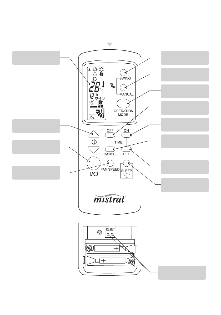
Operating procedure using the
Remote control
1. Start/Stop or On/Off
• Press I/O button to start operation, the unit
will stop when repressed.
2. Temperature adjustment
• Press TEMPERATURE ADJUSTMENT button,
decreases by 1˚C by pressing “ ” button
once.
• The temperature change will display in the
remote controller’s display.
3. Fan speed adjustment
• Pressing FAN SPEED button changes the fan
speed of indoor unit in the order of
(low)
(medium) (high)
(medium) (high)
(medium) (high)
(medium) (high)
(medium) (high)
(medium) (high)
(medium) (high)
(medium) (high)
(medium) (high)
(medium) (high)
(medium) (high)
(medium) (high)
(medium) (high)
(medium) (high)
(medium) (high)
(medium) (high)
(medium) (high)
(medium) (high)
(medium) (high)
(auto)
(auto)
(auto)
(auto)
(auto)
4. Sleep selection
• Press SLEEP button to set sleep operation,
this operation will cancel when the sleep
button is repressed.
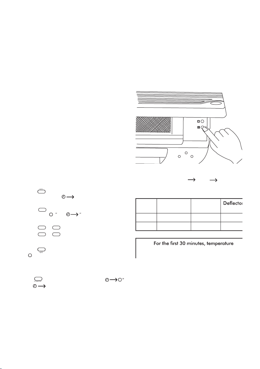
5. Air fl ow direction adjustment
• Change up/down air fl ow direction
1. Press the MANUAL SWING button, the defl ector
will move to a specifi c angle. Change the
defl ector of indoor unit following the order of
(1) (2) (3) (4) (5)(Fig.2)
(see page 6).
2. Press the SWING button, the defl ector will start
to operate.
• To change the air fl ow direction from left to
right.
You can manually adjust the swing defl ector, Left/
Right to change the air fl ow direction.
Complete adjustment before operation, if adjusted
during operation, the auto swinging defl ector may
pinch your fi ngers. (Fig.1) (see page 6).
1. Open back cover, put in batteries.
Notice
• If the remote control does not operate normally,
short circuit the RESET contacts, the unit will
then operate normally.
• The remote control will only operate within a six
metre range.
• Handle remote control carefully. Do not drop,
throw or allow any moisture to penetrate the
remote control.
• When a button is pressed, the indoor unit will
beep once or twice, indicating the signal has
been received. If no beep is heard, press again.
• Remove batteries if the remote control is not
to be used for a long time.

SLEEP
RU N
TI ME
by
7
ADVICE
• In DRY or COOL mode, ensure the Fan speed is
set to (auto), air blows downward in
direction (1). In HEAT mode, ensure the Fan
speed is set to (auto), air blows downward in
(4).
(4).
• Control the air direction with remote controller
to adjust up/down air fl ow direction. Avoid
turning defl ector with your hand to avoid injury.
6. Operation mode adjustment
• When the cool option has been selected no
HEAT will be produced.
1 AUTO mode
When started, the unit will automatcially select
COOL or DRY or HEAT mode according to the
room temperature, if operation is stopped for
two hours, the unit will restart in the same
mode set when the unit is stopped. Once
operation mode is set, it will not be infl uenced
even if room temperature has changed. Press
MANUAL SWING button or SWING button to
change up/down air fl ow direction.
COOL
mode
DRY
mode
HEAT
mode
Fig 1

2 COOL mode
Press MANUAL SWING button or SWING button
to change up/down air fl ow direction. Press FAN
SPEED button to change the fan speed of indoor
unit. Press TEMPERATURE ADJUSTMENT button
to change the temperature setting.
3 DRY mode
Press MANUAL SWING button or swing button
to change up/down air fl ow direction. Press FAN
SPEED button to change the fan speed of indoor
unit.
4 FAN mode
Press MANUAL SWING button or SWING button
to change up/down air fl ow direction. Press FAN
SPEED button to change the fan speed of indoor
unit.
5 HEAT mode
Press MANUAL SWING button or swing button
to change up/down air fl ow direction. Press FAN
SPEED button to change the fan speed of indoor
unit. Press TEMPERATURE ADJUSTMENT button
to change the temperature setting.
7. Timer operation (12 Hour)
• Timer operation ON
1 Press button when air conditioner is not
operating, “I” of “ I” will fl icker on the
Remote Controller display.
Press
button when air conditioner
operates, “
operates, “
”
of “
of “
of “
of “
of “
”
will fl icker on the
Remote Controller display.
2 Press
or
button to enter time setting.
Press
or
button once, and the timer
will increase by 1 hour, the time will display on
the Remote Controller.
3 Press buttonto enter time setting. “I” or
“
“
”
will stop fl ickering on the Remote
Controller display once the times have been set.
• Timer operation OFF
If you want to turn the timer operation off, press
the button until the set time and “
”
or “ I” disappears from the Remote
Controller display.
Operating procedure-
control under the
Emergency operation
switch
• Should the Remote Controller be faulty you can
use the manual operation switch located under
the top cover of the indoor unit. (see diagram
below).
Each time the switch is pressed, the operation
sequence changes COOL
HEAT STOP.
HEAT STOP.
HEAT STOP.
Emergency run operation procedure:
8

Service and Maintenance
WARNING
Before you clean the air conditioner, be sure to
disconnect the power supply plug.
Cleaning the indoor unit and the remote
controller
CAUTIONS
• Use a dry cloth to wipe the indoor unit and
remote controller.
• A dampened cloth with cold water may be used
on the indoor unit if it is very dirty.
• Never use a damp cloth on the remote
controller.
• Do not use chemically-treated dusters for
cleaning or leave such materials on the unit for a
long period of time, this it may damage or fade
the surface of the unit.
• Do not use benzine, thinners, polishing powder,
or similar solvents for cleaning. These may
cause the plastic surface to crack or deform.
If you do not plan to use the unit for at least 1
month.
1. Operate the fan only for about half a day to dry
the inside of the unit out.
2. Stop the air conditioner and disconnect power.
3. Remove the batteries from the remote
controller.
Check before operation
CAUTIONS
• Check that the wiring is not broken
and is
connected.
• Check that the air fi lter is installed.
• Check that the outdoor unit air outlet or inlet is
not blocked.
Before you clean the air conditioner, be sure to
disconnect the power supply plug.
9

10
Filters must be cleaned on a regular basis
FILTERS SHOULD BE CLEANED ONCE
EVERY TWO WEEKS
1. Take out fi lters
CLEAN DEODORIZATION FILTERS AND
AIR CLEANER
1. Take out fi lters fi rst, then take out
deodorization
fi lter and air cleaner.
2. Clean fi lters with a vacuum cleaner or by
tapping them gently. (If they are very dirty, wash
them in warm water below 45˚C with a
dissolved non scouring agent.)
2. Clean deodorization fi lter, and air cleaner with
warm water below 45
˚
C with non scouring
agent.
3. Rinse fi lters with clean water, then dry them in
cool air.
3. Rinse fi lters with clean water, then dry them in
cool air.
4. Insert them in their original position, then push
down and close the front panel.
4. Insert them in their original position, then push
down and close the front panel.

11
Fault
Air conditioner does not operate at all. u Is there a
power failure?
Remote controller does not display u If the
operation modes are changed too any information.
Cooling and heating effi ciency is poor.
Indoor unit fan stops for about 10 minutes during
heating.
You can hear the sound of running water
Fault Confi rmation and Analysis
If problems persist after performing the tests below, please stop the air conditioner and
contact our service centre nearest to you to get help.
If problems persist after performing the tests below, please stop the air conditioner and
Fault analysis
Is there a power failure?
Is the unit unplugged?
Is the power fuse or switch off?
Is the timer set correctly?
If the operation modes are changed too frequently
the remote controller may lose function.
If remote controller display is unclear or displays all
symbols, please change the batteries or reset.
Remove and replace batteries.
Is the temperature set to the correct level?
Are the fi lters clean?
Are doors and windows closed?
This is normal. The unit is defrosting the outdoor
unit coil. It should complete this process in about
10 minutes at most. (Freezing occurs when
outdoor temperature is low and humidity is high)
This is the sound of expanding refrigerant inside
the air conditioner.
Sound of accumulated water dropping on the
heat-exchanger.
The sound of melting frost on heat-exchanger.

NOTE
1. The indicated noise value is from laboratory test done before leaving the factory.
2. The rated cooling capacity and rated heating capacity value is tested under following conditions.
3. All of the above information may be changed without notice. These are the latest and accurate
specifi cations on the name plate of your air conditioner.
4.Working temperature range:
5. If air conditioner working voltage exceeds 230V±10% it may operate abnormally.
6. Wiring diagrams of air conditioner (indoor unit/outdoor unit) are attached to the unit.
7. If the power cable or connecting cable is damaged, it must be replaced by its service agent
or
similar qualifi ed person in order to avoid a hazard.
12
Performance Parameters

13
Performance Parameters
(Cont.)
NOTE
1. The indicated noise value is from laboratory tests done before leaving the factory.
2. The rated cooling capacity and rated heating capacity value is tested under following conditoner.
3. All of the above information may be changed without notice. These are the latest and
accurate specifi cations on the name plate of your air conditioner.
4. Working temperature range:
5. If air conditioner working voltage exceeds 230V±10% it may operate abnormally.
6. Wiring diagrams of air conditioner (indoor unit/outdoor unit) are attached to the unit.
7. If the power cable or connecting cable is damaged, it must be replaced by its service agent
or
similar qualifi ed person in order to avoid a hazard.

Installation Sketch
14

15
Installation Accessories
Before installation, inspect the following accessories:
1 Location of indoor unit
• Cooled or heated air should be blown to every
part of the room.
• Maximum distance between indoor/outdoor
units is 5m.
• Mount on fi rm wall to avoid any vibration.
• Avoid direct sunshine.
• Easy drain for condensation water.
• Avoid any interference caused by a fl uorescent
lamp to the remote control’s signal.
• Minimum distance between air conditioner and
home appliance (TV/Radio, etc.) is 1m.
Installation Instructions
2 Location of outdoor unit
• Airfl ow cannot be blocked.
• Good ventilation, low dust, avoid rain or
direct sunshine.
• Ensure operational noise of air blowing out of
unit does not affect neighbour’s comfort.
• Firmly mount on rack, to reduce noise
and vibration.
• Avoid places close to infl ammable gas leakage.
• Unit must be mounted fi rmly when installed high
up.
• Avoid exposure to strong wind.

16
Installation
1. Secure the mounting plate
• The mounting plate should be attached to the structural part of wall (post etc.)
2. Drill on the wall
• Confi rm the position of holes, and drill holes of ø65mm on the wall.
INDOOR UNIT
INDOOR UNIT
1. Open the front panel
2. Remove the screw from electrical box cover,
pull the box cover away from the unit and set
aside.
3. Remove the screw from fastener, pull the
fastener away from the unit and set aside.
4. Connect the cable
5. Replace the fastener and electrical box cover.

17
OUTDOOR UNIT
OUTDOOR UNIT
CONNECTING PIPE WORK
1. NOTE:
• The drain must be arranged beneath the
copper pipe.
• The drain hose must not be hunched or bent.
• When the drain hose runs through the house,
it should be wrapped with special heat
insulated materials.
• The copper pipe and the drain hose must be
wrapped by felt strip. Heat insulated pad should
be used in the place that the pipe contacts the
wall.
2. ROUTE OF PIPE:
• If pipe came out of the right side of the indoor
unit, cut part “1” on the unit.
• If pipe came out of the lower-right side of the
indoor unit, cut part “2” on the unit.
• If pipe came out of the left side of the indoor
unit, cut part “3” on the unit.
3. REFIT OF DRAIN HOSE
• If pipe comes out of the left side of the indoor
unit, the drain hose must be refi tted otherwise
water leakage
may occur.
• Refi t methods: Interchange the position of
drain hose and drain rubber bib, the right
diagram is normal position.
• Clearance is not possible after refi tting as it
leads to
water leakage.

18
INSTALLATION OF INDOOR UNIT
• Let pipe go through the wall hole and attach
the indoor unit to the mounting plate.
(Locate the rib of the indoor unit in the hole of
the mounting plate.)
THE CONNECTION OF PIPE
• The number of bends in the pipe of the indoor
unit should not exceed 10. The number of bends
in the pipe of the indoor unit and outdoor unit
should not exceed 15.
• The radius of bends should be more than 10cm.
A layer of air proof oil should be coated on the
joint before the pipe has been connected. Align
the axis of each pipe and tighten screw nut with
a spanner (see the right diagram).
ARRANGEMENT OF DRAIN HOSE
• To eject the condensated water easily, the drain hose should be positioned downward.
The arrangement in diagrams 2-5 are wrong.
• If the drain hose connected with the indoor
unit is short, it may be extended by the hose
in the accessory box.
• When the drain hose must be run through
the house, it should be wrapped by the
special heat insulated materials.
SEALING OF WALL HOLE AND
FASTENING
OF PIPE
• Use putty to seal the wall hole.
• Use clamp (pipe fastener) to secure the pipe
at specifi ed position.

19
INSTALL THE DRAIN JOINT
(heat pump type only)
• Install the double-channel drain joint in the
hole on the bottom of the outdoor unit’s
bottom, then connect drain hose and joint.
CONNECT CONNECTING PIPE
• Wipe the air sealing oil on the closing valve
and the trump extended pipe; Screw down
the nut of connecting pipe with the wrench.
(the torque is as the indoor unit)
DISCHARGING THE AIR WITHIN THE UNITS:
• Unscrew cap for closing valve gas charging
hole.
• Open the closing valve with Allen key (turn
90˚ clockwise), then push in the gas charging
hole for about 10 seconds, (Until a gas like
fog appears, this indicates the air within unit
is fully discharged.)
• Screw down the screw cap of the gas
charging hole.
• Test for leaks with leak detector or soapy
water.
ADD REFRIGERANT
• If the connecting pipe is longer than 7 meters, add refrigerant as needed.
(Heat pump type) A=(Lm-7m)x50g/m. (A: add refrigerant amount, L: the length of connecting pipe)
• Connect the refrigerant gas bottle with the gas charging hole;
(do not screw down the nut of the gas closing valve’s end.)
• Open the bottle’s valve of storage refrigerant, discharge the air of units with refrigerant;
• When gas like fog appears, indicating the air of unit is discharged, screw down the nut;
• Add refrigerant with the spring balance.
TEST
TEST
• Start leak test (with leak detector or soapy water) and inspect connecting cables before testing
operation. Test procedure: (Control unit by emergency operation switch or remote controller)
For detailed operation see “OPERATION OF AIR CONDITIONER.”

The benefi ts conferred by this warranty are in
addition to all implied warranties, other rights
and remedies in respect of the product which the
consumer has under the Trade Practices Act and
similar State and Territory Laws.
The original purchaser of this MISTRAL product is
provided with the following warranty, subject to
the following conditions.
Linda Australia Pty Ltd warrant this product
for a period of 5 years from the date of purchase
for all parts defective in workmanship or
materials. The product or defective parts will be
replaced free of charge.
WARRANTY CONDITIONS
1. This warranty is only valid for appliances used
according to the manufacturer’s instructions.
2. This appliance must not be modifi ed or changed
in any way.
3. Connection must be to the voltage requirements
as specifi ed in the ratings label located on the
product.
4. The manufacturer does not accept liability for
any direct or consequential damage, loss or
other expense arising from misuse or incorrect
installation and operation of the appliance.
5. Warranty will only be given where proof of
purchase is provided, e.g. original invoice.
6. Not designed or warranted for industrial or
commercial use.
7. Proof that the unit was installed by a fully
qualifi ed and competant tradesman and must be
produced if requested. Failure to do so will void
the warranty.
20
PLEASE SEND IN THIS WARRANTY TO:
ELECTRIC BLUE INSTALLATIONS
& SERVICE PTY LTD.
Fill out the following details and fi le with your
purchase invoice.
RETAIN & FILE WITH YOUR RECEIPT.
Your Purchase Receipt/Invoice is proof of date of
purchase. You must be able to present it at the
place of purchase to obtain a replacement or
service under warranty.
Linda Australia Pty Ltd
reserves the right to
discontinue items, modify designs and change
specifi cations without incurring obligation.
Whilst every effort is made to ensure that
descriptions, specifi cations and other information
in this publication is correct, no warranty is given
in respect thereof and the company shall not be
liable for any errors therein.
Purchased from:
Co. Name:
Address:
Date of Purchase:
NOTE: Consistent with our continuing product
development policy, improvements may have
been made which render the contents of this
package slightly different to that shown.
Cat. No.: MAS101-1HP, MAS151-1.5HP,
MAS201-2HP, MAS201SS-2HP
August 2004
Warranty
Product of Linda Aus
tralia
Pty Ltd
ABN 60 079 923 130
324 Frankston-Dandenong Road
Dandenong South, Victoria, Australia 3175
RINGGRIP
(NZ) Pty Ltd
ACN 006 771 922
PO Box 33672, Takapuna, Auckland NZ
Mistral is a registered trademark of Mistral International Pty Ltd.
©2001 Linda Australia Pty Ltd
After sales and service support (includes installation) is provided by:
Electric Blue Installations & Service Pty Ltd
324 Frankston-Dandenong Road, Dandenong South, Victoria 3175
This manual suits for next models
3
Table of contents
Other Mistral Air Conditioner manuals