manuals.online logo
Brands
  1. Home
  2. •
  3. Brands
  4. •
  5. Mistral
  6. •
  7. Air Conditioner
  8. •
  9. Mistral MSS10 User manual

Mistral MSS10 User manual

Reverse Cycle
Split System
Air Conditioner
MSS10 - 1HP
MSS15 - 1.5HP
MSS20 - 2HP
MSS25 - 2.5HP


 


Important Safeguards
When using electrical appliances, in order to
reduce the risk of re, electric shock, and/or
injury to persons, basic safety precautions should
be followed, including:
For Your Safety
Read all instructions carefully, even if you are
familiar with the appliance.
This appliance is not intended for use by
children or inrm persons without supervision.
Young children should be prevented from
playing with the appliance.
Switch off and remove the plug from the
power outlet before cleaning or when not in
use. To unplug, grasp the plug and pull from
the power outlet. Never pull cord.
Do not operate any appliance with a damaged
cord or plug, after the appliance malfunctions,
or is dropped or damaged in any manner.
Do not use any appliance for anything
other than its intended use. This product is
intended for household use only.
This appliance is intended to be plugged in a
240V power outlet only.
Do not misuse the cord. Never carry the
appliance by the cord or pull to disconnect it
from the outlet. Instead, grasp the plug and
pull to disconnect.
Do not attempt to repair, disassemble or
modify the appliance. There are no user-
serviceable parts.
Arrange the power cord away from trafc
areas where it will not be tripped over.
Do not insert or allow foreign objects to enter
the grille openings as this may cause damage
to the appliance and/or injury to the user.
NOTE
For proper performance, operate the unit under
the usable operating temperature and humidity
conditions indicated in this owner's manual. If
the unit operates beyond these conditions, it
may cause malfunctions of the unit or dew to
drip from the unit.
COMPULSORY WARNING
If the supply cord is damaged, it must be
replaced by the manufacturer or its service agent
or a similarly qualied person in order to avoid
a hazard.
This product has not been designed for any uses
other than those specied in this booklet.
Save These Instructions
Getting To Know Your
Air Conditioner
Congratulations on the purchase of your new
Split System Air Conditioner.
Before the rst use of your new Mistral unit,
it is most important that you read and follow
the instructions in this Use & Care booklet,
even if you feel you are quite familiar with this
type of appliance. Find a place and keep this
booklet handy for future reference. Attention is
particularly drawn to the section dealing with
“IMPORTANT SAFEGUARDS”.
This appliance has been designed to operate
from a standard 10AMP/15AMP outlet. It is not
intended for industrial or commercial use.
Hints for Economical
Operation
• Clean air lter.
A clogged air lter reduces cooling efciency
and should be cleaned once every two weeks.
• Avoid opening doors and windows more
often than necessary.
• Window curtains.
When heating or cooling, close the curtains.
This will prevent counteracting cooling effect
in summer and will reduce heat loss in winter.
• Use the timer effectively.
Set the timer for the desired operating time.
• Try to create a uniform circulation of room air.
Adjust air ow direction for even circulation
of room air.
Indoor Unit
2 3
Outdoor Unit
 

 



 
 
  
  

 
   



Filter Front panel Air inlet Power plug
Left / Right deector Deector
Display Remote
controller
Manual operation
(open the front panel)
Check switch
Emergency operation
switch
Time indicator
Sleep indicator
Run indicator
Air inlet
Connecting pipe
Drain hose
Air outlet
Drain opening
NOTICE
• If the remote control does not operate
normally, short circuit the RESET contacts, the
unit will then operate normally.
• The remote control will only operate within
a six metre range.
• Handle remote control carefully. Do not drop,
throw or allow any moisture to penetrate the
remote control.
• When a button is pressed, the indoor unit will
beep once or twice, indicating the signal has
been received. If no beep is heard, press again.
• Remove batteries if the remote control is not
to be used for a long time.
Remote Controller Operation of Air Conditioner
Operating procedure using the
remote control
1. Start/Stop or On/Off
• Press I/O button to start operation,
the unit will stop when repressed.
2. Temperature adjustment
• Press TEMPERATURE ADJUSTMENT
button, decreases by 1˚C by pressing
"q" button once.
• The temperature change will display in the
remote controller's display.
3. Fan speed adjustment
• Pressing FAN SPEED button changes the
fan speed of indoor unit in the order of
(low) ¨ (medium) ¨ (high) ¨
(auto)
4. Sleep selection
• Press SLEEP button to set sleep operation,
this operation will cancel when the sleep
button is repressed.
5. Air ow direction adjustment
• Change up/down air ow direction
1 Press the MANUAL SWING button,
the deector will move to a specic
angle. Change the deector of
indoor unit following the order of
(1)  (2)  (3)  (4)  (5)(Fig.2)
(see page 6).
2 Press the SWING button, the deector will
start to operate.
• To change the air ow direction from left
to right.
You can manually adjust the swing deector,
Left/Right to change the air ow direction.
Complete adjustment before operation,
if adjusted during operation, the auto
swinging deector may pinch your ngers.
(Fig.1) (see page 6).
4 5
Signal ejecting window
OPERATION DISPLAY
TEMPERATURE
ADJUSTMENT BUTTON
ON/OFF BUTTON
FAN SPEED BUTTON
SWING BUTTON
MANUAL SWING
BUTTON
OPERATION MODE
BUTTON
TIME OFF BUTTON
TIME ON BUTTON
TIME CANCEL BUTTON
TIME SET BUTTON
SLEEP BUTTON
RESET BUTTON
1. Open back cover, put in batteries.
2. Short circuit reset contacts with forceps.
(Short two RESET buttons after changing
the batteries).
Remote Control
Preparation
Battery Compartment
• Ensure batteries are inserted
in the correct direction.
• Do not mix battery types.
• When replaceing,
ensure both batteries are
changed simultaniously.
6 7
ADVICE
• In DRY or COOL mode, ensure the Fan
speed is set to
(auto), air blows downward
in direction (1). In HEAT mode, ensure
the Fan speed is set to
(auto), air blows
downward in (4).
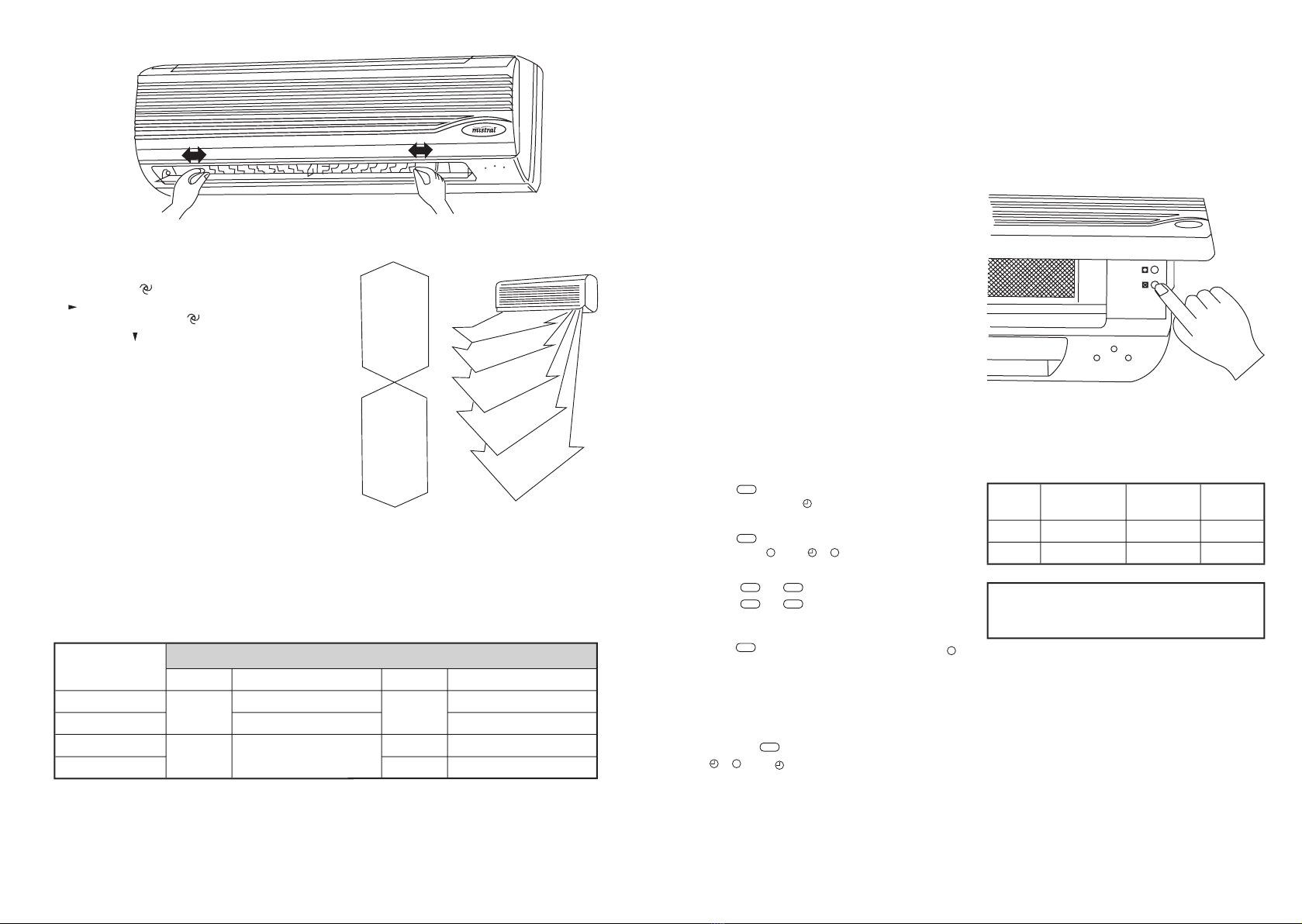
• Control the air direction with remote
controller to adjust up/down air ow
direction. Avoid turning deector with your
hand to avoid injury.
6. Operation mode adjustment
• When the cool option has been selected
no HEAT will be produced.
1 AUTO mode
When started, the unit will automatcially select
COOL or DRY or HEAT mode according to the
room temperature, if operation is stopped for
two hours, the unit will restart in the same
mode set when the unit is stopped. Once
operation mode is set, it will not be inuenced
even if room temperature has changed. Press
MANUAL SWING button or SWING button to
change up/down air ow direction.
Per Room
Temperature (RT)
Cooling only type Heat pump type
Mode Per Setting Temperature Mode Per Setting Temperature
above 26˚C Cool 24˚C Cool 24˚C
25-26˚C RT-2 RT-2
23-25˚C Dry RT-2 Dry RT-2
below 23˚C Heat 26˚C
Fig.1
 
 

 
 


 

 

COOL
mode
DRY
mode
HEAT
mode
(1)
(2)
(3)
(4)
(5)
Fig.2
2 COOL mode
Press MANUAL SWING button or SWING
button to change up/down air ow direction.
Press FAN SPEED button to change the fan
speed of indoor unit. Press TEMPERATURE
ADJUSTMENT button to change the
temperature setting.
3 DRY mode
Press MANUAL SWING button or swing
button to change up/down air ow direction.
Press FAN SPEED button to change the fan
speed of indoor unit.
4 FAN mode
Press MANUAL SWING button or SWING
button to change up/down air ow direction.
Press FAN SPEED button to change the fan
speed of indoor unit.
5 HEAT mode
Press MANUAL SWING button or swing
button to change up/down air ow direction.
Press FAN SPEED button to change the fan
speed of indoor unit. Press TEMPERATURE
ADJUSTMENT button to change the
temperature setting.
7. Timer operation (12 Hour)
• Timer operation ON
1 Press ON
button when air conditioner is not
operating, "I" of " I" will icker on the
Remote Controller display.
Press OFF
button when air conditioner
operates, "" of " " will icker on the
Remote Controller display.
2 Press ON or OFF
button to enter time setting.
Press ON or OFF
button once, and the timer
will increase by 1 hour, the time will display
on the Remote Controller.
3 Press SET buttonto enter time setting. "I" or " "
will stop ickering on the Remote Controller
display once the times have
been set.
• Timer operation OFF
If you want to turn the timer operation off,
press the CANCEL button until the set time and
"" or "I" disappears from the
Remote Controller display.
Operating procedure-control under the
Emergency operation switch
• Should the Remote Controller be faulty you can
use the manual operation switch located under
the top cover of the indoor unit. (see diagram
below).
Each time the switch is pressed, the operation
sequence changes COOL  HEAT  STOP.
Emergency run operation procedure:
Mode Setting
Temperature
Fan Speed Deector
COOL 24˚C High Swing
HEAT 24˚C High Swing
Note: For the rst 30 minutes, temperature
adjustment will not work. Continuous operation
will be maintained on high fan speed.
8 9
Service and Maintenance
WARNING
Before you clean the air conditioner, be sure to
disconnect the power supply plug.
Cleaning the indoor unit and the
remote controller
CAUTIONS
• Use a dry cloth to wipe the indoor unit and
remote controller.
• A dampened cloth with cold water may be
used on the indoor unit if it is very dirty.
• Never use a damp cloth on the remote
controller.
• Do not use chemically-treated dusters for
cleaning or leave such materials on the unit
for a long period of time, this it may damage
or fade the surface of the unit.
• Do not use benzine, thinners, polishing
powder, or similar solvents for cleaning.
These may cause the plastic surface to crack
or deform.
If you do not plan to use the unit for at
least 1 month.
1. Operate the fan only for about half a day to
dry the inside of the unit out.
2. Stop the air conditioner and disconnect power.
3. Remove the batteries from the remote
controller.
Check before operation
CAUTIONS
• Check that the wiring is not broken
and is connected.
• Check that the air lter is installed.
• Check that the outdoor unit air outlet or inlet
is not blocked.
Before you clean the air conditioner, be sure to
disconnect the power supply plug.
FILTERS SHOULD BE CLEANED ONCE EVERY
TWO WEEKS
1. Take out lters
2. Clean lters with a vacuum cleaner or by
tapping them gently. (If they are very dirty,
wash them in warm water below 45˚C with a
dissolved non scouring agent.)
3. Rinse lters with clean water, then dry them
in cool air.
4. Insert them in their original position, then
push down and close the front panel.
CLEAN DEODORIZATION FILTERS AND AIR
CLEANER
1. Take out lters rst, then take out
deodorization lter and air cleaner.
2. Clean deodorization lter, and air cleaner
with warm water below 45˚C with non
scouring agent.
3. Rinse lters with clean water, then dry them
in cool air.
4. Insert them in their original position, then
push down and close the front panel.
Filters must be cleaned on a regular basis
10 11
Fault Conrmation and Analysis
n If problems persist after performing the tests below, please stop the air conditioner and
contact our service centre nearest to you to get help.
Fault Fault analysis
Air conditioner does not operate at all. u Is there a power failure?
Is the unit unplugged?
Is the power fuse or switch off?
Is the timer set correctly?
Remote controller does not display u If the operation modes are changed too
any information. frequently the remote controller may lose function.
If remote controller display is unclear or displays all
symbols, please change the batteries or reset.
Remove and replace batteries.
Cooling and heating efciency is poor. u Is the temperature set to the correct level?
Are the lters clean?
Are doors and windows closed?
Indoor unit fan stops for about 10 minutes u This is normal. The unit is defrosting the outdoor
during heating. unit coil. It should complete this process in about
10 minutes at most. (Freezing occurs when
outdoor temperature is low and humidity is high)
You can hear the sound of running water u This is the sound of expanding refrigerant inside
the air conditioner.
Sound of accumulated water dropping on the
heat-exchanger.
The sound of melting frost on heat-exchanger.
Performance Parameters
Model MSS10 - 1HP MSS15 - 1.5HP
indoor outdoor indoor outdoor
Function heat pump type heat pump type
Power 230V~, 50Hz 230V~, 50Hz
Rated cooling/heating capacity (W) 2000/2400 3500/4000
Standard input power (W) 750(cool)/730(heat) 1300(cool)/1380(heat)
Standard input current (A) 3.5(cool)/3.4(heat) 6.2(cool)/6.6(heat)
Air ow volume (m³/h) 300 450
Dehumidifying capacity (L/h) 1.0 1.6
Protection I
Water-proof IP20(INDOOR) IP24(OUTDOOR)
Climate type T1
Refrigerant (R22) charge amount (g) 560 1120
Noise dB (A) 31 45 40 48
Net weight (Kg) 10 26 11 37
Dimension (mm) WxHxD 800x183x290 665x295x500 800x183x290 830x310x500
NOTE 1. The indicated noise value is from laboratory test done before leaving the factory.
2. The rated cooling capacity and rated heating capacity value is tested under following conditions.
cooling operation indoor 27˚C (DB) 19˚C (WB) outdoor 35˚C (DB) 24˚C (WB)
heating operation indoor 20˚C (DB) 15˚C (WB) outdoor 7˚C (DB) 6˚C (DB)
3. All of the above information may be changed without notice. These are the latest and
accurate specications on the name plate of your air conditioner.
4. Working temperature range:
Maximum cooling Minimum cooling Maximum cooling Minimum cooling
Indoor side (DB/WB (˚C) 32/23 21/15 27/-- 20/--
Outdoor side DB/WB (˚C) 43/26 21/15 24/18 -5/-6
5. If air conditioner working voltage exceeds 230V±10% it may operate abnormally.
6. Wiring diagrams of air conditioner (indoor unit/outdoor unit) are attached to the unit.
7. If the power cable or connecting cable is damaged, it must be replaced by its service agent
or similar qualied person in order to avoid a hazard.
Performance Parameters (cont.)
Model MSS20 - 2HP
indoor outdoor
Function heat pump type
Power 220-240V~, 50Hz
Rated cooling/heating capacity (W) 5100(cool)/5700(heat)
Standard input power (W) 1960(cool)/2000(heat)
Standard input current (A) 9.0(cool)/9.2(heat)
Air ow volume (m³/h) 750
Dehumidifying capacity (L/h) 2.5
Protection I
Water-proof IP20 IP24
Climate type T1
Refrigerant (R22) charge amount (g) 1650
Noise dB (A) 43 55
Net weight (Kg) 12 46
Dimension (mm) WxHxD 1020x180x315 800x300x685
NOTE 1. The indicated noise value is from laboratory tests done before leaving the factory.
2. The rated cooling capacity and rated heating capacity value is tested under following conditions.
cooling operation indoor 27˚C (DB) 19˚C (WB) outdoor 35˚C (DB) 24˚C (WB)
heating operation indoor 20˚C (DB) 15˚C (WB) outdoor 7˚C (DB) 6˚C (DB)
3. All of the above information may be changed without notice. These are the latest and
accurate specications on the name plate of your air conditioner.
4. Working temperature range:
Maximum cooling Minimum cooling Maximum cooling Minimum cooling
Indoor side (DB/WB (˚C) 32/23 21/15 27/-- 20/--
Outdoor side DB/WB (˚C) 43/26 21/15 24/18 -5/-6
5. If air conditioner working voltage exceeds 230V±10% it may operate abnormally.
6. Wiring diagrams of air conditioner (indoor unit/outdoor unit) are attached to the unit.
7. If the power cable or connecting cable is damaged, it must be replaced by its service agent
or similar qualied person in order to avoid a hazard.
12 13
Performance Parameters (cont.)
Model MSS25 - 2.5HP
indoor outdoor
Function heat pump type
Power 230V~, 50Hz
Rated cooling/heating capacity (W) 6800(cool)/7500(heat)
Standard input power (W) 2500(cool)/2590(heat)
Standard input current (A) 12.1(cool)/12.6(heat)
Air ow volume (m³/h) 1100
Dehumidifying capacity (L/h) 3.3
Protection I
Water-proof IP20 IP24
Climate type T1
Refrigerant (R22) charge amount (g) 2350
Noise dB (A) 50 58
Net weight (Kg) 15 65
Dimension (mm) WxHxD 1080x220x330 870x365x850
NOTE 1. The indicated noise value is from laboratory tests done before leaving the factory.
2. The rated cooling capacity and rated heating capacity value is tested under following conditions.
cooling operation indoor 27˚C (DB) 19˚C (WB) outdoor 35˚C (DB) 24˚C (WB)
heating operation indoor 20˚C (DB) 15˚C (WB) outdoor 7˚C (DB) 6˚C (DB)
3. All of the above information may be changed without notice. These are the latest and
accurate specications on the name plate of your air conditioner.
4. Working temperature range:
Maximum cooling Minimum cooling Maximum cooling Minimum cooling
Indoor side (DB/WB (˚C) 32/23 21/15 27/-- 20/--
Outdoor side DB/WB (˚C) 43/26 21/15 24/18 -5/-6
5. If air conditioner working voltage exceeds 230V±10% it may operate abnormally.
6. Wiring diagrams of air conditioner (indoor unit/outdoor unit) are attached to the unit.
7. If the power cable or connecting cable is damaged, it must be replaced by its service agent
or similar qualied person in order to avoid a hazard.
14 15
Installation Sketch
Conrm installation position
with the marker of indoor
unit installation board.
Notice: Do not put the drain
hose higher than the outlet.
The pipe can be congured for
installation to the back, right,
underside, or left-back side
Cover connecting pipe with
heat-isolating material.
The thickness of heat-isolating
material should be 8mm.
When installing connecting
pipe on a wall that is metallic
mesh or thin armour plate,
place a wooden block with
a thickness over 20mm
between the wall and
connecting pipe with 7 or 8
layers of bonding tape.
Installation Accessories
Before installation, inspect the following accessories:
Indoor unit accessories Quantity Installation accessories Quantity
1 Mounting plate 1 A Connecting pipe 1
2 Tapping screw ST4 x 25 5 B Bonding tape 1
3 Expansion rubber plug 5 C Clamp 3
4 Expansion bolt 2 D Cement nail 5
5 Battery 2 E Drain hose 1
6 Remote controller 1 F Opening cap 1
7 Felt 1 G Wall-hole cover 1
8 Adiabatic underlay 1 H Indoor wall-hole cover 1
9 connecting cable 1 I putty 1
10 Drain joint
(supplied by customer) 1
J Air sealing oil 1
KShockproof rubber cushion
(supplied by customer) 4
Installation Instructions
1 Location of indoor unit
• Cooled or heated air should be blown to
every part of the room.
• Maximum distance between indoor/outdoor
units is 5m.
• Mount on rm wall to avoid any vibration.
• Avoid direct sunshine.
• Easy drain for condensation water.
• Avoid any interference caused
by a uorescent lamp to the remote
control's signal.
• Minimum distance between air conditioner
and home appliance (TV/Radio, etc.) is 1m.
2 Location of outdoor unit
• Airow cannot be blocked.
• Good ventilation, low dust, avoid rain or
direct sunshine.
• Ensure operational noise of air blowing out of
unit does not affect neighbour's comfort.
• Firmly mount on rack, to reduce noise
and vibration.
• Avoid places close to inammable gas leakage.
• Unit must be mounted rmly when installed
high up.
• Avoid exposure to strong wind.
16 17
Installation
1. Secure the mounting plate
• The mounting plate should be attached to the structural part of wall (post etc.)
NOTE: • Holes indicated by solid arrows must be secured to avoid mounting plate shaking.
• When the expansion bolts are used, two holes (11x20 or 11x26) 450mm apart
should be adopted.
2. Drill on the wall
• Conrm the position of holes, and drill holes of ø65mm on the wall.
¢ INDOOR UNIT
1. Open the front panel
2. Remove the screw from electrical box
cover, pull the box cover away from the
unit and set aside.
3. Remove the screw from fastener, pull the
fastener away from the unit and set aside.
4. Connect the cable
5. Replace the fastener and electrical box cover
¢ OUTDOOR UNIT
WARNING:
• The connecting cables must be clipped together.
• Special cable must be used to connect indoor unit and outdoor unit. Ensure that the
terminals are not inuenced by external forces. Poor connections may cause a re.
• The electric box cover must be mounted and secured in position, otherwise re or electrical
shock may occur because of dust or moisture.
• If necessary, consult your supply authority for system impedance information.
¢ CONNECTING PIPE WORK
1. NOTE:
• The drain must be arranged beneath the copper pipe.
• The drain hose must not be hunched or bent.
• When the drain hose runs through the house, it should
be wrapped with special heat insulated materials.
• The copper pipe and the drain hose must be wrapped
by felt strip. Heat insulated pad should be used in the
place that the pipe contacts the wall.
2. ROUTE OF PIPE:
• If pipe came out of the right side of the indoor unit,
cut part "1" on the unit.
• If pipe came out of the lower-right side of the indoor
unit, cut part "2" on the unit.
• If pipe came out of the left side of the indoor unit, cut
part "3" on the unit.
3. REFIT OF DRAIN HOSE
• If pipe comes out of the left side of the indoor unit, the
drain hose must be retted otherwise water leakage
may occur.
• Ret methods: Interchange the position of drain hose and
drain rubber bib, the right diagram is normal position.
• Clearance is not possible after retting as it leads to
water leakage.
WARNING: When re-installing the piping and drain hose they should be removed via the
position, otherwise there might be a risk of electric shock.
18 19
¢ INSTALLATION OF INDOOR UNIT
• Let pipe go through the wall hole and attach
the indoor unit to the mounting plate.
(Locate the rib of the indoor unit in the hole
of the mounting plate.)
¢ THE CONNECTION OF PIPE
• The number of bends in the pipe of the
indoor unit should not exceed 10. The
number of bends in the pipe of the indoor
unit and outdoor unit should not exceed 15.
• The radius of bends should be more than 10cm.
A layer of air proof oil should be coated on the
joint before the pipe has been connected. Align
the axis of each pipe and tighten screw nut with
a spanner (see the right diagram).
PIPE DIAMETER OF PIPE TORQUE (N • m)
Liquid pipe 6.35mm (1/4") 13.7---17.6
Gas pipe 9.52mm (3/8") 34.3---41.2
Gas pipe 12.7mm (1/2") 49.0---56.4
¢ ARRANGEMENT OF DRAIN HOSE
• To eject the condensated water easily, the drain hose should be positioned downward.
The arrangement in diagrams 2-5 are wrong.
• If the drain hose connected with the indoor
unit is short, it may be extended by the hose
in the accessory box.
• When the drain hose must be run through
the house, it should be wrapped by the
special heat insulated materials.
¢ SEALING OF WALL HOLE AND
FASTENING OF PIPE
• Use putty to seal the wall hole.
• Use clamp (pipe fastener) to secure
the pipe at specied position.
dispose of unwanted part
screw
clamp
¢ INSTALL THE DRAIN JOINT
(heat pump type only)
• Install the double-channel drain joint in the
hole on the bottom of the outdoor unit's
bottom, then connect drain hose and joint.
¢ CONNECT CONNECTING PIPE
• Wipe the air sealing oil on the closing valve
and the trump extended pipe; Screw down the
nut of connecting pipe with the wrench.
(the torque is as the indoor unit)
¢ DISCHARGING THE AIR WITHIN THE UNITS:
• Unscrew cap for closing valve gas
charging hole.
• Open the closing valve with Allen key (turn
90˚ clockwise), then push in the gas charging
hole for about 10 seconds, (Until a gas like
fog appears, this indicates the air within unit
is fully discharged.)
• Screw down the screw cap of the gas
charging hole.
• Test for leaks with leak detector or soapy water.
¢ ADD REFRIGERANT
• If the connecting pipe is longer than 7 meters, add refrigerant as needed.
(Heat pump type) A=(Lm-7m)x50g/m. (A: add refrigerant amount, L: the length of connecting pipe)
the length of connecting pipe (m) 7 8 9 10
(Heat pump type) add amount (g) 0 50 100 150
• Connect the refrigerant gas bottle with the gas charging hole;
(do not screw down the nut of the gas closing valve's end.)
• Open the bottle's valve of storage refrigerant, discharge the air of units with refrigerant;
• When gas like fog appears, indicating the air of unit is discharged, screw down the nut;
• Add refrigerant with the spring balance.
NOTE: • Do not overturn the bottle of storage refrigerant, when adding refrigerant to the unit;
• Heat up the bottle of storage refrigerant with warm water (about 40˚C), do not
use an exposed ame or hot steam.
¢ TEST
• Start leak test (with leak detector or soapy water) and inspect connecting cables before testing
operation. Test procedure: (Control unit by emergency operation switch or remote controller)
For detailed operation see "OPERATION OF AIR CONDITIONER."
PLEASE SEND IN THIS WARRANTY TO:
ELECTRIC BLUE I & S PTY LTD.
Fill out the following details and le with your
purchase invoice.
RETAIN & FILE WITH YOUR RECEIPT.
Your Purchase Receipt/Invoice is proof of date of
purchase. You must be able to present it at the
place of purchase to obtain a replacement or
service under warranty.
Mistral International Pty Ltd reserves the right to
discontinue items, modify designs and change
specications without incurring obligation.
Whilst every effort is made to ensure that
descriptions, specications and other information
in this publication is correct, no warranty is given
in respect thereof and the company shall not be
liable for any errors therein.
Purchased from:
Co. Name:
Address:
Date of Purchase:
NOTE: Consistent with our continuing product
development policy, improvements may have
been made which render the contents of this
package slightly different to that shown.
Warranty
The benets conferred by this warranty are in
addition to all implied warranties, other rights
and remedies in respect of the product which the
consumer has under the Trade Practices Act and
similar State and Territory Laws.
The original purchaser of this MISTRAL product is
provided with the following warranty, subject to
the following conditions.
Mistral International Pty Ltd warrant this product
for a period of 5 years from the date of purchase
for all parts defective in workmanship or
materials. The product or defective parts will be
replaced free of charge.
WARRANTY CONDITIONS
1. This warranty is only valid for
appliances used according to the
manufacturer’s instructions.
2. This appliance must not be modied or
changed in any way.
3. Connection must be to the voltage
requirements as specied in the ratings
label located on the product.
4. The manufacturer does not accept liability
for any direct or consequential damage,
loss or other expense arising from misuse
or incorrect installation and operation of
the appliance.
5. Warranty will only be given where proof of
purchase is provided, e.g. original invoice.
6. Not designed or warranted for industrial
or commercial use.
7. Proof that the unit was installed by a fully
qualied and competant tradesman and
must be produced if requested. Failure to
do so will void the warranty.
Product of Linda Australia Pty Ltd ABN 60 079 923 130
324 Frankston - Dandenong Road
Dandenong-South, Victoria, Australia 3175
Telephone +61 3 9212 1333 Facsimile +61 3 9212 1340
RINGGRIP (NZ) Pty Ltd ACN 006 771 922
PO Box 33672 Takapuna, Auckland, New Zealand
Telephone 0 800 328 280 Facsimile 0 800 328 238
Mistral is a registered trademark of Mistral International Pty. Ltd.
© 2002 Mistral International Pty. Ltd
After sales and service support (includes installation) is provided by:
Electric Blue Installations & Service Pty Ltd
324 Frankston-Dandenong Road, Dandenong South, Victoria 3175
Telephone 13 63 39
June 2003
Cat. No. MSS10-1HP, MSS15-1.5HP, MSS20-2HP, MSS25-2.5HP

This manual suits for next models

3

Other Mistral Air Conditioner manuals

Mistral MAC 152 User manual

Mistral

Mistral MAC 152 User manual

Mistral MKAC180 User manual

Mistral

Mistral MKAC180 User manual

Mistral MCCT25SS User manual

Mistral

Mistral MCCT25SS User manual

Mistral MAS101 User manual

Mistral

Mistral MAS101 User manual

Mistral MTP-09IN User manual

Mistral

Mistral MTP-09IN User manual

Mistral MA02016KRY30 User manual

Mistral

Mistral MA02016KRY30 User manual

Popular Air Conditioner manuals by other brands

Panasonic CUG95KE operating instructions

Panasonic

Panasonic CUG95KE operating instructions

Daikin APGM3 Service and Troubleshooting

Daikin

Daikin APGM3 Service and Troubleshooting

Mitsubishi Electric Mr. Slim MXZ-2B20NA Service manual

Mitsubishi Electric

Mitsubishi Electric Mr. Slim MXZ-2B20NA Service manual

Whirlpool COOL IMPRESSION SERIES owner's manual

Whirlpool

Whirlpool COOL IMPRESSION SERIES owner's manual

Fluo FMV-ND224PH/A-T owner's manual

Fluo

Fluo FMV-ND224PH/A-T owner's manual

EIC Solutions AAC-161B Series Installation and operation manual

EIC Solutions

EIC Solutions AAC-161B Series Installation and operation manual

Rinnai rhfe-553ft Customer's operating information and installation instructions

Rinnai

Rinnai rhfe-553ft Customer's operating information and installation instructions

Fujitsu AR A45LCTU Series Design & technical manual

Fujitsu

Fujitsu AR A45LCTU Series Design & technical manual

Kenmore 580.751515 Repair parts list

Kenmore

Kenmore 580.751515 Repair parts list

Black & Decker BPACT14H Series instruction manual

Black & Decker

Black & Decker BPACT14H Series instruction manual

Frigidaire FAC104P1A Use & care manual

Frigidaire

Frigidaire FAC104P1A Use & care manual

Carrier Performance 12 owner's manual

Carrier

Carrier Performance 12 owner's manual

ALPATEC AC S 141 ET user manual

ALPATEC

ALPATEC AC S 141 ET user manual

Daikin RXL42K2V1B installation manual

Daikin

Daikin RXL42K2V1B installation manual

Carrier 48VL Owner's information manual

Carrier

Carrier 48VL Owner's information manual

Stulz CVC 07 001yy operating instructions

Stulz

Stulz CVC 07 001yy operating instructions

Fujitsu AOU9RLF installation manual

Fujitsu

Fujitsu AOU9RLF installation manual

Mitsubishi Electric Mr. Slim MXZ-3B24NA installation manual

Mitsubishi Electric

Mitsubishi Electric Mr. Slim MXZ-3B24NA installation manual

manuals.online logo
manuals.online logoBrands
  • About & Mission
  • Contact us
  • Privacy Policy
  • Terms and Conditions

Copyright 2025 Manuals.Online. All Rights Reserved.