Mistral MCCT25SS User manual

Ceiling Cassette Type
Split System
MCCT25SS - 2.5 HP
MCCT40SS - 4 HP
MCCT40SS - 4 HP

FOR YOUR SAFETY
Read all instructions carefully, even if you are
familiar with the appliance.
• This appliance is not intended for use by
children or infi rm persons without supervision.
• Young children should be prevented from
playing with the appliance.
• Switch off and remove the plug from the
power outlet before cleaning or when not in
use. To unplug, grasp the plug and pull from
the power outlet. Never pull cord.
• Do not operate any appliance with a damaged
cord or plug, after the appliance malfunctions,
or is dropped or damaged in any manner.
• Do not use any appliance for anything other
than its intended use. This product is intended
for household use only.
• The MCCT25SS is intended to be plugged
into a 240V, single phase power outlet only.
The MCCT40SS is intended to be plugged into a
380V, 3 phases power outlet only.
• Do not misuse the cord. Never carry the
appliance by the cord or pull to disconnect it
from the outlet. Instead, grasp the plug and
pull to disconnect.
• Do not attempt to repair, disassemble or
modify the appliance. There are no user
serviceable parts.
• Arrange the power cord away from traffi c areas
where it will not be tripped over.
• Do not insert or allow foreign objects to enter
the grille openings as this may cause damage
to the appliance and/or injury to the user.
2
COMPULSORY WARNING
If the supply cord is damaged, it must be
replaced by the manufacturer or its service agent,
or a similarly qualifi ed person, in order to avoid a
hazard.
This product has not been designed for any uses
other than those specifi ed in this booklet.
SAVE THESE INSTRUCTIONS
Important Safeguards
In order to reduce the risk of fi re, electric
shock, and/or injury to persons when using
electrical appliances, basic safety precautions
should be followed, including:
NOTE :
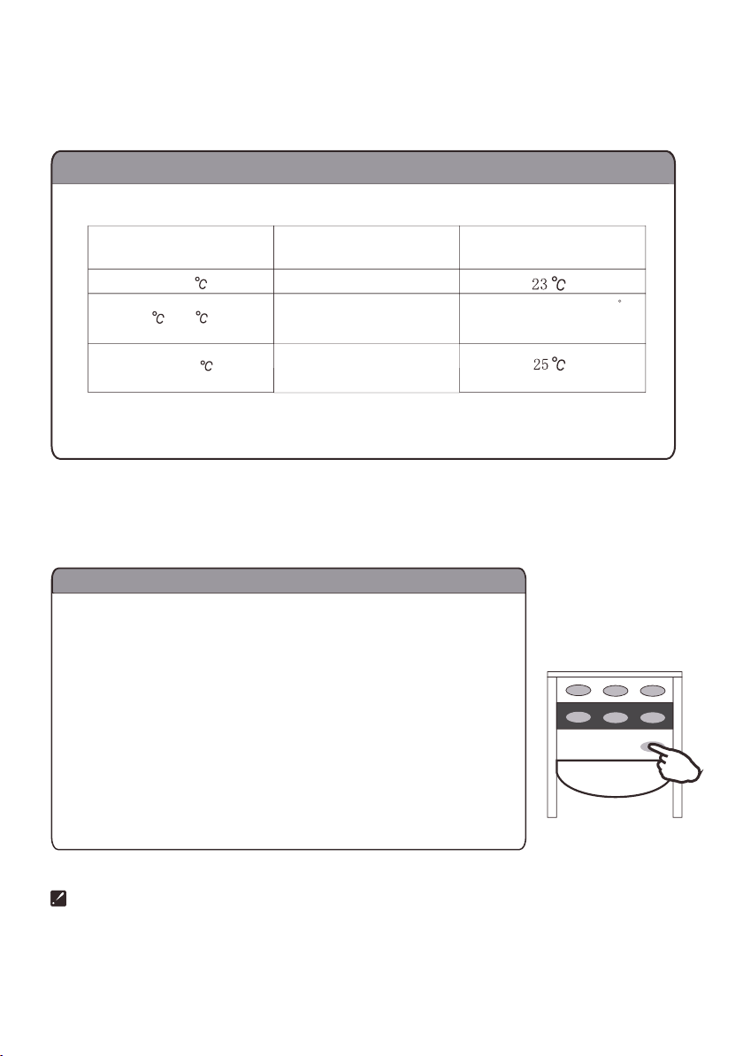
For proper performance, operate the unit under
the usable operating temperature and humidity
conditions indicated in this owner’s manual. If the
unit operates beyond these conditions, it may
cause malfunctions of the unit or dew to drip from
the unit.

3
Getting To Know Your
Air Conditioner
Congratulations on the purchase of your new
Mistral Ceiling Cassette Type Air Conditioner.
Before fi rst using you new unit it is important that
you read and follow the instructions in this Use &
Care booklet, even if you are familiar with this type
of appliance.
Keep this booklet in a safe place for future
reference.
Please pay particular attention to the “IMPORTANT
SAFEGUARDS” section.
Hints for Economical Operation
• Clean air fi lter. A clogged air fi lter reduces
cooling effi ciency and should be cleaned once
every two weeks.
• Avoid opening doors and windows more often
than necessary.
• Window curtains. When cooling, close the
curtains. This will prevent counteracting cooling
effect in summer and will reduce heat loss in
winter.
• Try to create a uniform circulation of room air.
Adjust air fl ow direction for even circulation of
room air.

Note: The condensate water drains
at COOLING or Dry operation.
4
Identifi cation of parts
The diagrams in this booklet are based on the external view of a standard model and may
differ from the air conditioner you purchased.
Indoor Unit
Outdoor Unit

On: Timer in Use.
Off: Timer cycle complete.
On: Water Pump running.
Flashing: Drain Failure.
On: Heater in use.
Receives signal from
the remote controller.
RUN TIMER DRAIN HEATER
On: Unit is in operation.
Flashes for 10 seconds when setting
SLEEP mode.
5
Identifi cation of parts
Operating and Display

send signal to appliance.
Press once to turn on
and press again to off
For presetting the time
to turn the air
conditioner on or off.
After setting the timer,
press once to confirm.
For setting operation
mode
Press once the start
the electric heater
in heating mode, press
again to cancel.
Press to set and press
again to cancel
Press to cancel timer
To adjust air flow
direction
signal transmit.
high fan speed
medium fan speed
low fan speed
For adjusting room
temperature
Sleep indicator
Heating indicator
Electric heater
indicator
Cooling indicator
Dry indicator
Fan only indicator
"I FEEL" mode
Press once to
raise the set
temperature by 1
I FEEL
HI
h
LOW
FAN ON/OFF
TEMP
SLEEP SWING MODE
CAN SET TIMER
HEATER
Press once to
lower the set
temperature by 1
auto fan speed
Press to select the
indoor fan speed.
6
Identifi cation of parts
Remote controller
The remote control continues displaying even after the unit has stopped operation.

Signal
transmitter
The range that the signal can reach
is about 7m when pointing at the
front of indoor unit.
Signal-sent symbol will flash
for a short time when signal is sent.
No signal
is received
Remote controller
is exposed to
directsunlightor
strong spotlight
"Beep" means
receiving signal
TIMER
SET
CAN
MODE
SWING
SLEEP
Pull to open
the cover.
Load batteries in the
compartment
according to polarity.
Push up to close
the cover.
The service life of an alkaline battery is about 1 year.
When the indoor unit does not response to signal, or
the display becomes dim, replace the batteries at once.
Replace the two batteries with new ones of the same
type.
To prevent damage due to leakage, remove the
batteries when the unit is not used for long periods
of time.
HEATER
7
Identifi cation of parts
Remote controller
• If the remote control unit does not
display correctly after replacing the
batteries, remove them and reload after
20 seconds.
• Be sure to stop the air conditioner
before loading the batteries.

8
Operation of Air Conditioner
• Operation procedure using the remote control
Operation modes
• If the unit does not respond when changing modes during operation, wait 3 minutes and try
again.
• When heating mode is selected the unit will not discharge the airfl ow until the indoor heater
exchange temperature has risen suffi ciently, approximately after 2.5 minutes.
• Wait 3 minutes before restarting the unit.
Each time the MODE button is pressed, the operation mode
is changed in sequence:
Press until your desired mode appears.
Each time the "FAN" button is pressed, the fan speed is
changed in sequence:
"I FEEL "mode is specified on page 9.
The compressor does not run in "FAN ONLY " mode.
18 ~32
HEATING
"I FEEL" COOLING DRY FAN ONL
Y
2
+
-
AUTO HI MED LO
.
At "FAN ONLY" mode, only "HI","MED" and "LO" are available.
When in DRY mode the airflow is set by the Air conditioner
automatically, the FAN button is ineffective in this mode.
Press once to lower temperature by 1
Press once to raise temperature by 1
Range of available set temperature
unable to set
room temperature
To turn on the unit press the ON/OFF button, a beep
indicates the signal is received from the remote control
and the RUN indicator will light up.

I FEEL
h
ON/OFF
Press the SWING button on the remote to control the swinging
and stopping of air vanes.
Press the SWING button once, the
fan motor starts to operate, and the
air vanes swing vertically.
Press the SWING button when the
airflow reaches your desired direction,
the fan motor will stop operating, and
the air vanes stop.
(desired direction) (desired direction)
9
Caution: Do not adjust or stop the air vanes manually as this may damage the unit. If
the air vanes stop working, turn off the unit and remove from the power supply. Re-
store the power supply and switch on the unit, this may reset the air vanes.
To prevent moisture from forming and dripping from the air vanes during COOLING or
DRY operation do not leave in a static downward position.
Moisture may form and drip from the air inlet when the unit is operating in COOLING or
DRY mode in high-humidity conditions (higher than 85%).
After long periods of operation, the air inlet may be covered with dust, wipe clean with
a soft cloth.

10
“I FEEL” mode
Press the “ON/OFF” button, choose the “I FEEL” mode by pressing “MODE” button.
The air conditioner will select heating, cooling or dry mode automatically, the temperature and fan speed will
be automatically determined according to the room temperature.
Room temperature Set temperature
21 ~25
Above 25
below 21
Operation mode
HEATING
DRY
COOLING
Room temp decrease1.5 C
after running 3 minutes
Electric heating mode
If fast heating is required, use the electric heating mode. This will assist the normal heating mode and output
warm air faster.
When you do not want to use the electric heater, it is recommended to switch off the power
supply to the electric heater for safety.
Use remote controller to set electrical heating mode.
Press the "HEATER" BUTTON in heating mode. The HEATER indicator
on the indoor unit lights on, and the electric heater starts to function.
(When temperature reaches a certain point, the electric heater will stop
automatically, and restart once temperature decreases to a certain point.
Press the "HEATER"button in electric heating mode to cancel.
The HEATER indicator lights off and the unit returns to normal heating
mode.
TIMER
HEATER
SET
CAN
MODE
SLEEP SWING

Timer-setting
Setting a switch-on
timer when the
appliance is off.
Setting a switch-off timer
during operation.
I FEEL
HI
h
LOW
FAN ON/OFF
TEMP
SLEEP SWING MODE
CAN SET TIMER
11
Timer operation mode
The timer can be set with the “TIMER” button to switch on the unit when unattended, allowing you to enjoy
a pleasant environment upon your arrival. You can also set the timer to turn off the unit at night.
The LCD displays the remaining time.
The previous set time is stored and the next set time begins with
the previous one.
Timer ON & OFF cannot be set at the same time.
The time taken to pre-heat/cool a room will depend on the size of
the room.
The TIMER indicator on the front panel lights up when the timer is
in use and turns off when the session is cancelled or fi nished.
I FEEL
I FEEL
I FEEL
HI
HI
HI
h
h
LOW
LOW
LOW
Press the TIMER button, "h" flashes on the LCD, then you can set the timer.
Each time the button is pressed, the set time increases by half an hour within 10 hours;
increases by one hour beyond 10 hours.
The timer range can be set is 0.5 hour to 24 hours.
Set the operating mode, temperature and indoor fan speed first, then
press the "TIMER" button until "9.5h" appears.
Point the remote controller at the signal receiving section of the indoor unit,
press the "SET" button when the letter "h" flashes.
A "beep" can be heard:
Timer indicator on the indoor unit lights up.
Letter "h" stops flashing.
To cancel the set timer: press the "CAN" button, a "beep" can be heard
and the timer indicator on the indoor unit turns off.
3

12
SLEEP mode

Service and Maintenance
WARNING
Before you clean the air conditioner, be sure to
disconnect the power supply plug.
Cleaning the indoor unit and the remote
controller
CAUTIONS
• Use a dry cloth to wipe the indoor unit and
remote controller.
• A dampened cloth with cold water may be used
on the indoor unit if it is very dirty.
• Never use a damp cloth on the remote
controller.
• Do not use chemically-treated dusters for
cleaning or leave such materials on the unit for a
long period of time, this it may damage or fade
the surface of the unit.
• Do not use benzine, thinners, polishing powder,
or similar solvents for cleaning. These may
cause the plastic surface to crack or deform.
If you do not plan to use the unit for at least 1
month.
1. Operate the fan only for about half a day to dry
the inside of the unit out.
2. Stop the air conditioner and disconnect power.
3. Remove the batteries from the remote
controller.
Check before operation
CAUTIONS
• Check that the wiring is not broken
and is
connected.
• Check that the air fi lter is installed.
• Check that the outdoor unit air outlet or inlet is
not blocked.
Before you clean the air conditioner, be sure to
disconnect the power supply plug.
13

14
Maintenance
Turn off the appliance
first before disconnecting
from the power supply.
shock!
Electric
Dangerous!
Use lukewarm water
(below 40 ) to clean
if the appliance
is very dirty.
Operate the unit at FAN ONLY
mode for half a day to dry the
inside of it on a sunny day.
soft cloth to
clean it.
Use a dry and
ON
O F
F

15
Maintenance
Make sure the surface is safe before climbing on to clean the unit.

Fault
Air conditioner does not operate at all.
Remote control does not display.
Cooling and heating effi ciency is poor.
Indoor unit fan stops for about 10 minutes during
heating.
You can hear the sound of running water
Fault Confi rmation and Analysis
If problems persist after performing the tests below, please stop the air conditioner and
contact the Mistral Service centre for help.
If problems persist after performing the tests below, please stop the air conditioner and
Fault analysis
Is there a power failure?
Is the unit unplugged?
Is the power fuse or switch off?
Is the timer set correctly?
If the operation modes are changed too frequently
the remote control may stop functioning.
If the remote control display is unclear or displays
all symbols, please change the batteries or reset.
Remove and replace batteries.
Is the temperature set to the correct level?
Are the fi lters clean?
Are doors and windows closed?
This is normal. The unit is defrosting the outdoor
unit coil. It should complete this process in about
10 minutes at most. (Freezing occurs when
outdoor temperature is low and humidity is high)
This is the sound of expanding refrigerant inside
the air conditioner.
Sound of accumulated water dropping on the
heat-exchanger.
The sound of melting frost on heat-exchanger.
16

17
Performance Parameters
NOTE
1. The indicated noise value is from laboratory test done before leaving the factory.
2. The rated cooling capacity and rated heating capacity value is tested under following conditions.
3. All of the above information may be changed without notice. These are the latest and accurate
specifi cations on the name plate of your air conditioner.
4. If air conditioner working voltage exceeds 230V±10% it may operate abnormally.
5. Wiring diagrams of air conditioner (indoor unit/outdoor unit) are attached to the unit.
6. If the power cable or connecting cable is damaged, it must be replaced by its service agent
or
similar qualifi ed person in order to avoid a hazard.
Model
MCCT25SS
MCCT40SS
Power
Single phase, 230-240V~, 50Hz
3 phase, 380V~, 50Hz
Rated Coolin
g
/
Heating
Capacity (w)
7100/7800
12000/12900
Sta
n
dard Input Power
Cool
ing/Heating
(w)
2700/2750
4600/5100
Standard input Current
Cool
ing/Heating
(A)
12.5/12.8
9.0/10.0
Air Folw Volume (m3/h)
1100
1600
Dehumidifying Capacity (L/h)
2.8
5
Protection
Water-proof
(Indoor/Outdoor)
Water-proof (Indoor/Outdoor)Water-proof
IP20/
IP24
IP20/
IP24
Climate Type
TI
TI
Refrigerant (R22) Charge Amount (g)
2400
3200
Noise dB (A)
(Indoor/Outdoor)
46/46
52/61
Net Weight (kg)
(Indoor/Outdoor)
35/56
46/90
Dimention (mm) W x H x D
(
Pa
nel /
Indoor / Outdoor
)
950 x 40 x 950/
840 x 220 x 840/
832 x 702 x 380
950 x 40 x 950/
840 x 320 x 840/
890 x 793 x 414
I

Ceiling
Roof Wall
Drain pipe
H>250mm
Over 1000mm
Over1500mm
Over1500mm
Over 1500mm
Over 1500mm
Elevation
Elevation
Returned oil elbow
18
Select the installation locations
Location for installing indoor unit:
• Where there is no obstacle near the air outlet and air can be
easily blown to every corner.
• Where drain pipe can extend to outside of the wall from the
ceiling board. It is preferable to have a special draining facility.
• Where the roof is strong enough to bear the weight of the indoor
unit , and will not increase the operating sound or vibration.
• Unobstructed area for the air inlet grille.
•
Keep the unit and remote controller 1m or more apart from
television, radio etc.
•
K
eep the main unit at least 5m away from fl uorescent lamps to
prevent any effect on them.
•
The maximum connecting piping length between indoor and
outdoor units is 20m, and the maximum elevation between the
units is
10
m.
•
Avoid installing in a dirty or greasy area.
Height of ceiling board
•
Install the unit in an area where the ceiling board in 2-3.5m above
the ground.
Location for installing outdoor unit:
•
A convenient, well ventilated area; avoid installing where
fl ammable gas could leak.
• Keep the outdoor unit at least 100mm away from the wall.
(over 500mm at the side of connecting piping)
• The maximum length of connecting piping is 20m. For a
connecting pipe exceeding 10m, additional refrigerant (20 gram)
should be added per meter. If the position of the outdoor unit is
higher than that of the indoor unit, connect an elbow to the entry
pipe of the indoor unit.(as in the fi g shown)
• When installed in certain areas e.g. greasy or dirty place, near
a
vulcanization gas exit or seashore (high salt area), make sure to
adopt insulation methods.
• Avoid installing the unit in an area where there is a risk splash or
fl ood.
• Where your neighbors would not be effected by operating noise
and hot airfl ow discharge.
• On a fi xed base where it is not subject to increasing the operating
noise.
• Where there is no obstruction of the air outlet.

H
L1 L1
L
19
Indoor unit installation
(Note: Below reference is only applicable to a house made of concrete.)
• Measure the distance H between the roof surface and the ceiling board ;
• Make four suspending poles with M10 screw thread on both ends (metric system) as the below
fi gure shown.(processed with 10 pole)
Value of L and L1 are calculated as below
L1=50mm (when H<255mm L1=40mm
L=1.5L1+H-230 (unit: mm)
• Turn 4 attached nuts onto the thread ends on the suspending poles as shown below:
• Take out the moulding board from the packing carton of indoor unit, do not fold it, just use it to
decide an installation location and direction of the unit on the roof and ceiling.
Press the moulding board tightly onto the surface of the roof, draw out the hole position for expand bolt
with a pencil, then take off the moulding board, drill 8 holes for the expand bolts. It is preferable if the
depth of holes just reveal the thread of the poles.
• Cut an opening (880x880) on the ceiling board with assistance of the moulding board, make sure
to follow the same direction of the holes for roof bolts. Fix the edges of the opening with the [-shaped
aluminum bars.
•
Mount the attached suspending brackets with expand bolts M8X50 on the roof surface.
Make sure to tighten the expand bolts and nuts well. The opening of suspending brackets should face
outward as shown below.
• Take out the suspending poles with nut on one end, mount them on the fi xed suspending bracket, then
tighten the nuts and washers on the top of the suspending brackets.

8~13mm
Water pipe
Leveling ruler
4-12 18 hole
390mm
414mm
790mm
• Fix the main unit onto the suspending poles with attached nuts and washer. The nuts on the bottom
should turn to about half of the thread length.
( Note: This procedure requires at least 2 people.)
• Adjust the nuts on the bottom of the suspending poles, allow the bottom of the unit 8-13mm higher than
that of the ceiling board. (as the above fi gure shown)
Then adjust each corner of the bottom horizontally with a leveling ruler.
( Level should be within the scope of 1/100.)
Outdoor unit installation
• Install it on a strong and fl at surface or bracket.
• Keep it at least 150mm above the ground.
• Fix with 4 M8X60 bolts to avoid vibration or other accidents.
20
This manual suits for next models
1
Table of contents
Other Mistral Air Conditioner manuals
Popular Air Conditioner manuals by other brands

Gree
Gree GWHD(14)NK6OO(LC)(LH) Service manual

Hokkaido
Hokkaido HKEI-HCNI 263 XR Service manual

Samsung
Samsung AS07P2GE/XCH Owner's instructions

Mitsubishi Electric
Mitsubishi Electric Mr.Slim MS-GK36VA operating instructions

Technibel
Technibel KPAFP165R5IA Series installation manual

Sanyo
Sanyo THX2452 user manual