MITSUBISHI ELECTRIC ENGINEERING FA1-TE40PA User manual

Spring Clamp Terminal Block Conversion Adapter
MODEL
User’s Manual
(Detailed Edition)
Time and Wire Saving Devices
FA1-TE40PA

2
SAFETY PRECAUTIONS
(Read these precautions before using the products.)
Before using the products, please read this manual and the relevant manuals carefully, and pay full
attention to safety to handle the products correctly.
The precautions given in this manual are concerned with time and wire saving devices only.
For the safety precautions of the programmable controller system, refer to the user's manual for the
programmable controller used.
If the equipment is used in a manner not specified by the manufacturer, the protection provided by
the equipment may be impaired.
In this manual, the safety precautions are classified into two levels: " WARNING" and
"CAUTION".
WARNING
Indicates that incorrect handling may cause hazardous conditions,
resulting in death or severe injury.
CAUTION
Indicates that incorrect handling may cause hazardous conditions,
resulting in minor or moderate injury or property damage.
Under some circumstances, failure to observe the precautions given under " CAUTION" may lead
to serious consequences.
Observe the precautions of both levels because they are important for personal and system safety.
[Design Precautions]
WARNING
●Configure safety circuits externally to ensure that the entire system operates safely even when a fault occurs in the
external power supply, the programmable controller, or the products. Failure to do so may result in an accident
due to an incorrect output or malfunction.
(1) Emergency stop circuits, protection circuits, and protective interlock circuits for conflicting operations (such as
forward/reverse rotations or upper/lower limit positioning) must be configured externally.
(2) Outputs may remain on or off due to a failure of a component such as a relay, transistor, and triac used for
digital signal converter outputs. Configure an external circuit for monitoring output signals that could cause a
serious accident.
●In an output circuit for digital signal converter outputs, when a load current exceeding the rated current or an
overcurrent caused by a load short-circuit flows for a long time, it may cause smoke and fire. To prevent this,
configure an external safety circuit, such as a fuse.
●Configure a circuit so that the programmable controller is turned on first and then the external power supply. If
the external power supply is turned on first, an accident may occur due to an incorrect output or malfunction.
3
[Design Precautions]
CAUTION
●Do not install the control lines or communication cables together with the main circuit lines or power cables. Keep
a distance of 100mm (3.94 inches) or more between them. Failure to do so may result in malfunction or failure
due to noise.
●When using a terminal block conversion module for a high-speed counter module, do not install the control lines
or communication cables together with the main circuit lines or power cables. Keep a distance of 150mm (5.91
inches) or more between them. Failure to do so may result in malfunction or failure due to noise.
●Keep a distance of 100mm (3.94 inches) or more between a thermocouple or RTD (Resistance Temperature
Detector) and the main circuit line or AC control lines. Also, keep the thermocouple or RTD away from a circuit that
includes harmonics, such as a high-voltage circuit and a load circuit of an inverter. If not, the thermocouple or RTD
is more likely to be affected by noise, surges, and induction.
●At power-on or power-off, a voltage may occur or a current may flow between output terminals for a moment. To
use an analog signal converter or analog terminal block conversion module, start the control after analog outputs
become stable.
●Do not place an analog signal converter or analog terminal block conversion module near a device that generates
magnetic noise.
●When a device such as a lamp, heater, or solenoid valve is controlled using a module for digital signal converter
outputs, a large current (approximately 10 times greater than normal) may flow when the output is turned from
off to on. Therefore, select a module for digital signal converter outputs that has a sufficient current rating.
[Installation Precautions]
WARNING
●Shut off the external power supply (all phases) used in the system before installation. Failure to do so may result
in electric shock or damage to the products.
[Installation Precautions]
CAUTION
●Use products in an environment that meets the general specifications in this manual. Failure to do so may result in
electric shock, fire, malfunction, or damage to or deterioration of the products.
●Securely fix the products with a DIN rail or screws. Incorrect installation may cause malfunction, failure, or drop of
the module. When using the products in an environment of frequent vibrations, fix the products with screws.
●Tighten the screws within the specified torque range. Undertightening can cause drop of the screw, short circuit,
or malfunction. Overtightening can damage the screw and/or products, resulting in drop,
short circuit, or
malfunction.
●Attach DIN rail stoppers on the right and left sides of the spring clamp conversion module to fix the module securely.
●Shut off the external power supply (all phases) used in the system before mounting or removing the products.
Failure to do so may result in damage to, malfunction of, or failure of the products.
●Do not directly touch any conductive parts and electronic components of the products. Failure to do so may cause
malfunction or failure of the products.
●Install the products in the correct orientation if it is specified. Failure to do so may result in damage to or
deterioration of the products.
●When drilling screw holes, be careful not to drop chips into the inside of the products or conductive parts. Such
foreign matter can cause a fire, failure, or malfunction.
●When using modules for replacing digital signal converters or signal conversion modules, use them in the correct
combination. Incorrect combination may cause failure.
●Shut off the power supply before installing/removing a module for replacing digital signal converters. Failure to do
so may cause failure or malfunction.
●Securely mount a module for replacing digital signal converters and signal conversion module on a digital signal
converter and installation base. Failure to do so may cause damage to or drop of the products, or malfunction due
to poor contact. Follow the correct procedure to install/remove them. Failure to do so may cause damage to or
drop of the products, or malfunction due to poor contact.
●When a module for digital signal converters or signal conversion module is mounted on a digital signal converter
or installation base, hold the digital signal converter or installation base to transport them or install them to a panel.
Holding the module for digital signal converters or signal conversion module may cause drop or failure of the digital
signal converter or installation base.
4
[Wiring Precautions]
WARNING
●Shut off the external power supply (all phases) used in the system before wiring. Failure to do so may result in
electric shock or damage to the products.
●After wiring, attach the included terminal cover to the products before turning them on for operation. Failure to do
so may result in electric shock.
[Wiring Precautions]
CAUTION
●Use applicable solderless terminals and tighten them within the specified torque range. Failure to do so may cause
failure, damage, or malfunction.
●Check the rated voltage and terminal layout before wiring to the products, and connect the cables correctly.
Connecting a power supply with a different voltage rating or incorrect wiring may cause a fire or failure.
●Do not install the control lines or communication cables together with the main circuit lines or power cables. Keep
a distance of 100mm or more between them. Failure to do so may result in malfunction due to noise.
●When using a terminal block conversion module for a high-speed counter module, do not install the control lines or
communication cables together with the main circuit lines or power cables. Keep a distance of 150mm (5.91 inches)
or more between them. Failure to do so may result in malfunction or failure due to noise.
●Keep a distance of 100mm (3.94 inches) or more between a thermocouple or RTD (Resistance Temperature
Detector) and the main circuit line or AC control lines. Also, keep the thermocouple or RTD away from a circuit that
includes harmonics, such as a high-voltage circuit and a load circuit of an inverter. If not, the thermocouple or RTD
is more likely to be affected by noise, surges, and induction.
●Do not place an analog signal converter or analog terminal block conversion module near a device that generates
magnetic noise.
●Place the cables in a duct or clamp them. If not, dangling cable may swing or inadvertently be pulled, resulting in
damage to the products or cables or malfunction due to poor contact.
●Tighten the terminal screws within the specified torque range. Undertightening can cause short circuit, fire, or
malfunction. Overtightening can damage the screw and/or products, resulting in drop, short circuit, or malfunction.
●Tighten the connector screws within the specified torque range. Undertightening can cause short circuit, fire, or
malfunction. Overtightening can damage the screw and/or products, resulting in drop, short circuit, fire, or
malfunction.
●Securely connect connectors to the products. Failure to do so may cause malfunction.
●When disconnecting a cable from the products, do not pull the cable by the cable part. For the cable with connector,
hold the connector part of the cable. For the cable connected to the terminal block, loosen the terminal screw.
Pulling the cable connected to the products may result in malfunction or damage to the products or cable.
●Check the interface type and correctly connect the cable. Incorrect wiring (connecting the cable to an incorrect
interface) may cause failure of the products and external device.
●Prevent foreign matter such as dust or wire chips from entering the products. Such foreign matter can cause a fire,
failure, or malfunction.
●The products must be installed in control panels. Connect the main power supply to the products in the control
panel through a relay terminal block. Wiring and replacement of the products must be performed by qualified
maintenance personnel with knowledge of protection against electric shock.
●When connecting the products with a programmable controller, check that the product configuration is correct. An
incorrect configuration may cause failure or malfunction.
●Use the products with no force applied to their connectors. Applied force may cause failure or disconnection.
●Attach protective covers or signal conversion modules to unused connectors or empty slots of the products. Failure
to do so may cause a fire, failure, or malfunction due to foreign matter.
●When using modules for replacing digital signal converters or signal conversion modules, use them in the correct
combination. Incorrect combination may cause failure of a programmable controller, digital signal converter,
installation base, or external device.
●Securely mount modules for replacing digital signal converters and signal conversion modules on a digital signal
converter and installation base. Failure to do so may cause damage to or drop of the products, or malfunction due
to poor contact. Follow the correct procedure to install/remove them. Failure to do so may cause damage to or
drop of the products, or malfunction due to poor contact.
●Individually ground the FG terminal of the products with a ground resistance of 100 ohms or less. Failure to do so
may result in electric shock or malfunction.

5
[Startup and Maintenance Precautions]
WARNING
●Do not touch any terminal while power is on. Doing so will cause electric shock or malfunction.
●Shut off the external power supply (all phases) used in the system before cleaning the products or retightening the
terminal screws, connector screws, or products fixing screws. Failure to do so may result in electric shock or cause
failure or malfunction of the products. Undertightening can cause drop of the screw, short circuit, or malfunction.
Overtightening can damage the screw and/or products, resulting in drop, short circuit, or malfunction.
[Startup and Maintenance Precautions]
CAUTION
●Do not disassemble or modify the products. Doing so may cause failure, malfunction, injury, or a fire.
●Use any radio communication device such as a cellular phone or PHS (Personal Handy-phone System) more than
25cm away in all directions from the programmable controller and products. Failure to do so may cause malfunction.
●Shut off the external power supply (all phases) used in the system before mounting or removing the products.
Failure to do so may cause failure or malfunction of or damage to the products.
●After the first use of the products, do not connect/remove the products and cables more than 50 times. Exceeding
the limit may cause malfunction.
●Startup and maintenance of a control panel must be performed by qualified maintenance personnel with knowledge
of protection against electric shock. Lock the control panel so that only qualified maintenance personnel can operate
it.
●The ESD susceptibility symbol shown below is placed on the products. This symbol products is susceptible static
electricity passed. Before handling the connector, touch a conducting object such as a grounded metal to release
the static electricity from your body. Failure to do so may cause the products to fail or malfunction. Do not touch
the connector when the products is powered. Doing so may result in injury or cause the products to malfunction
due to the static electricity in your body.
[Disposal Precautions]
CAUTION
●When disposing of the products, treat them as industrial waste.
[Transportation Precautions]
CAUTION
●Do not apply shock that exceeds the shock resistance described in the general specifications during transportation
since the products are precision devices. Doing so may cause failure of the module.
●The halogens (such as fluorine, chlorine, bromine, and iodine), which are contained in a fumigant used for
disinfection and pest control of wood packaging materials, may cause failure of the products. Prevent the entry of
fumigant residues into the product or consider other methods (such as heat treatment) instead of fumigation. The
disinfection and pest control measures must be applied to unprocessed raw wood.
EMC and Low Voltage Directives
Compliance with the EMC Directive, which is one of the EU directives, has been mandatory for products sold within EU
member states since 1996 as well as compliance with the Low Voltage Directive since 1997.
For products compliant to the EMC and Low Voltage Directives, their manufacturers are required to declare compliance
and affix the CE marking.
(1) Sales representative in EU member states
The sales representative in EU member states is:
Company: MITSUBISHI ELECTRIC EUROPE B.V.
Address: Mitsubishi-Electric-Platz 1, 40882 Ratingen, Germany
(2) Method of ensuring compliance*1
To ensure that products maintain EMC and Low Voltage Directives when incorporated into other machinery or
equipment, certain measures may be necessary. Please refer to "EMC and Low Voltage Directives Compliant Manual"
(50D-FA9010-108).
*1: The FA1-TE40PA are excluded.

6
REVISIONS
*The manual number is given on the bottom left of the last page.
Print Date
*Manual Number
Revision
August, 2020
50D-FG0474
First edition
September, 2020 50D-FG0474-AAdded parts
Connectable modules addition︓RD77MS2,QD77MS2
5-2. Wiring to a spring clamp terminal block,
8.CONNECTABLE MODULES
September, 2023 50D-FG0474-B Added parts
Connectable modules addition:Q172DLX,Q172LX
Q173DPX,Q173PX,Q173PX-S1
5-2. Wiring to a spring clamp terminal block
8. CONNECTABLE MODULES
This manual confers no industrial property rights or any rights of any other kind, nor does it confer any patent
licenses. Mitsubishi Electric Engineering cannot be held responsible for any problems involving industrial property
rights which may occur as a result of using the contents noted in this manual.
© 2020(2023) MITSUBISHI ELECTRIC ENGINEERING COMPANY LIMITED

7
CONTENTS
SAFETY PRECAUTIONS ···································································································2
EMC and Low Voltage Directives······················································································· 5
REVISIONS ···················································································································6
CONTENTS····················································································································7
1. INTRODUCTION ·········································································································8
2. GENERAL SPECIFICATIONS ·························································································8
3. PERFORMANCE SPECIFICATIONS ·················································································9
4. PART NAMES ··········································································································· 10
5. CONNECTING METHOD ····························································································· 11
5-1. Connection to a programmable controller···························································· 11
5-2. Wiring to a spring clamp terminal block ······························································ 12
6. INTERNAL WIRING DIAGRAM ···················································································· 15
7. APPLICABLE SOLDERLESS TERMINALS(Ferrule)···························································· 16
8.CONNECTABLE MODULES························································································· 17
9.EXTERNAL DIMENSIONS ·························································································· 18
9-1. Spring Clamp Terminal Block Conversion Adapter (FA1-TE40PA) ···························· 18
9-2. Depth and height···························································································· 19
10. PRECAUTIONS ······································································································· 20
11. GRATIS WARRANTY TERMS AND GRATIS WARRANTY RANGE······································· 20
12. EXCLUSION FROM LIABILITY FOR OPPORTUNITY LOSS AND SECONDARY LOSS ············· 20
13. TRADEMARKS ········································································································ 20
8
1. INTRODUCTION
This manual describes the specifications and handling of the spring clamp terminal block conversion adapter used in
combination with Mitsubishi Electric Corporation programmable controller I/O modules, high-speed counter modules, or
Positioning modules.
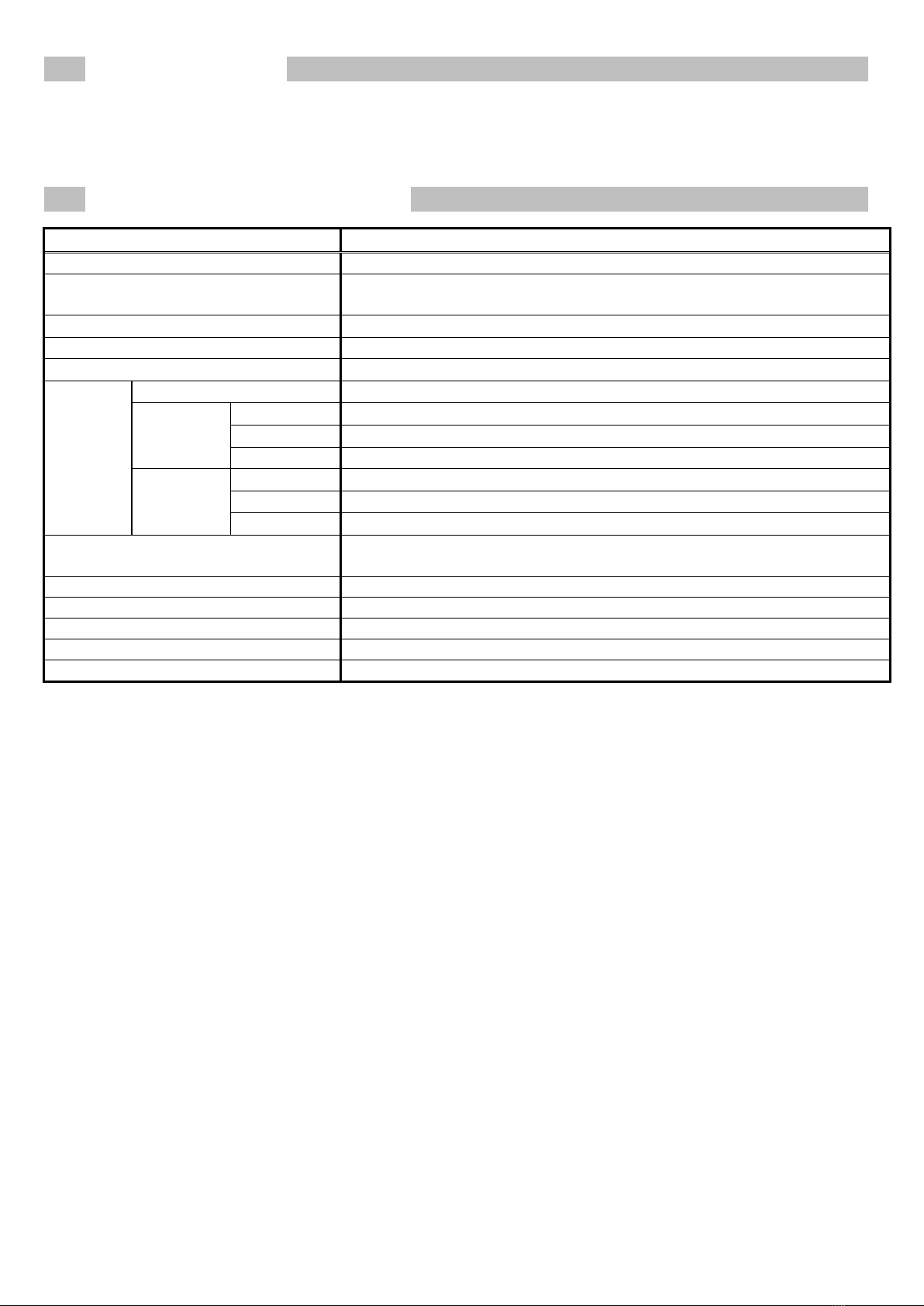
2. GENERAL SPECIFICATIONS
Item
Specifications
Model
FA1-TE40PA
Operating ambient temperature 0 to 55°C(When an extended temperature range base unit is not used)
0 to 60
°
C (When an extended temperature range base unit is used)
Storage ambient temperature
-25 to 75
°
C
Operating ambient humidity
5 to 95%RH, non-condensing
Storage ambient humidity
5 to 95%RH, non-condensing
Vibration
resistance
Compliance with standards
JIS B 3502, IEC 61131-2
Under
intermittent
vibration
5 to 8.4Hz
Half amplitude: 3.5mm
8.4 to 150Hz
Constant acceleration: 9.8m/s2(1G)
Sweep count
10 times each in X, Y, and Z directions
Under
continuous
vibration
5 to 8.4Hz
Half amplitude: 1.75mm
8.4 to 150Hz
Constant acceleration: 4.9m/s
2
(0.5G)
Sweep count
-
Shock resistance Compliant with JIS B 3502 and IEC 61131-2
(147m/s
2
(15G), 3 times each in X, Y, and Z bidirections)
Operating atmosphere
No corrosive gases
Operating altitude*1
2000m or lower
Installation location
Inside a control panel*4, Indoor use
Overvoltage category*2
II or less
Pollution degree*3
2 or less
*1: Do not use or store the products under pressure higher than the atmospheric pressure of altitude 0m. Doing so
may cause malfunction.
*2: This category indicates the section of the power supply to which the equipment is assumed to be connected between
the public electrical power distribution network and the machinery within premises.
*3: This index indicates the degree to which conductive material is generated in terms of the environment in which the
equipment is used.
*4: The enclosure is suitably designed for those specific environmental conditions, as applicable, and enclosure rate
meets IP20 and minimum type 1 of UL 50.

9
3. PERFORMANCE SPECIFICATIONS
Model
Item
FA1-TE40PA
Number of points
40 points
Rated voltage
24VDC(Class2 or SELV+LIM)*3
Maximum operating voltage
30VDC(Class2 or SELV+LIM)*3
Maximum operating current
0.5A/pt,2A/pt(1A,2A,1B,2B)
Terminal
block
Number of terminals
40 terminals
Applicable
wire*1*2
When a ferrule is not used
(stranded wire or solid wire)
0.2 to 1.5mm
2
(24 to 16 AWG),
Copper wire with a temperature rating of 75°C or more
When a ferrule is used
(stranded wire)
0.08 to 0.75mm
2
(28 to 18 AWG),
Copper wire with a temperature rating of 75°C or more
Wire strip length
8mm
Applicable tightening
torque
Mounting bracket fixing screw
(M2.6×4)
0.20 to 0.29N・m
C
onversion adapter anchor
base installation screw
(M3×20)
0.43 to 0.57N・m
Withstand voltage
500VAC for 1 minute
Insulation resistance (initial) 10MΩ or more
(measured with 500VDC insulation resistance tester)
Weight About 100g
(including the mounting bracket and screws)
*1: Select wires depending on the current value used.
*2: For UL certification, suitable for field wiring when a ferrule is not used.
*3: The power supply must use CLASS 2 power supply or a power supply conforming to the SELV
(Safety Extra-Low Voltage) and LIM(Limited Energy Circuit) circuit.
10
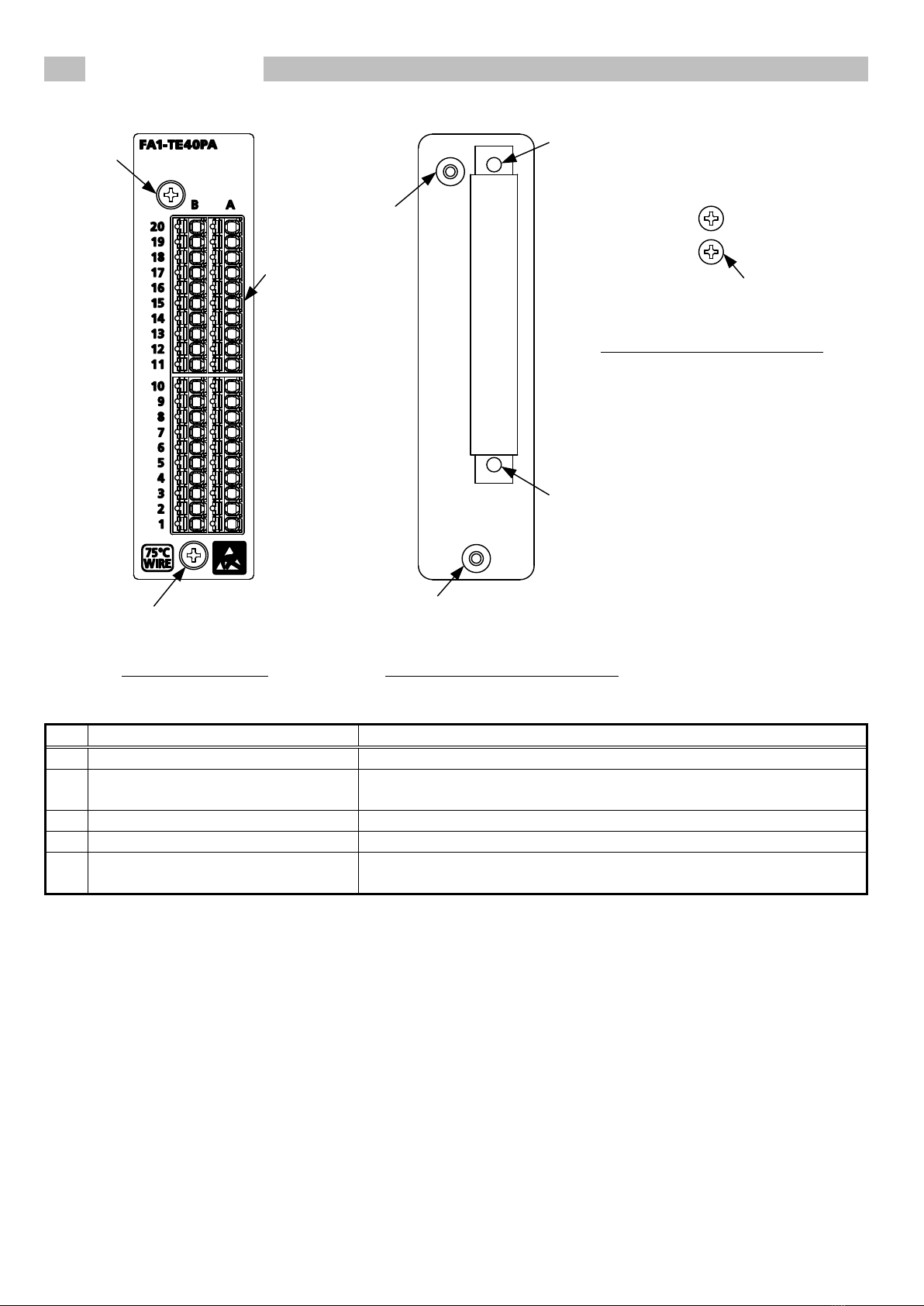
4. PART NAMES
(1)
(4)
(2)
(5)
(2)
(3)
(4)
(3)
Conversion adapter Mounti ng bracket(included item)
Mounti ng bracket fixing screw
(M2.6×4)(included item)
No.
name
Description
(1)
Spring clamp terminal block
This is a terminal block to connect external signals.
(2) Conversion adapter installation screw
(M3×20)
This is a screw to install the conversion adapter on the mounting
bracket.
(3)
Mounting bracket fixing hole
This is a hole to fix the mounting bracket to a programmable controller.
(4)
Conversion adapter mounting hole
This is a hole to fix the conversion adapter to the mounting bracket.
(5) Mounting bracket fixing screw
(M2.6×4)(included item)
This is a screw to fix the mounting bracket to a programmable controller.
11
5. CONNECTING METHOD
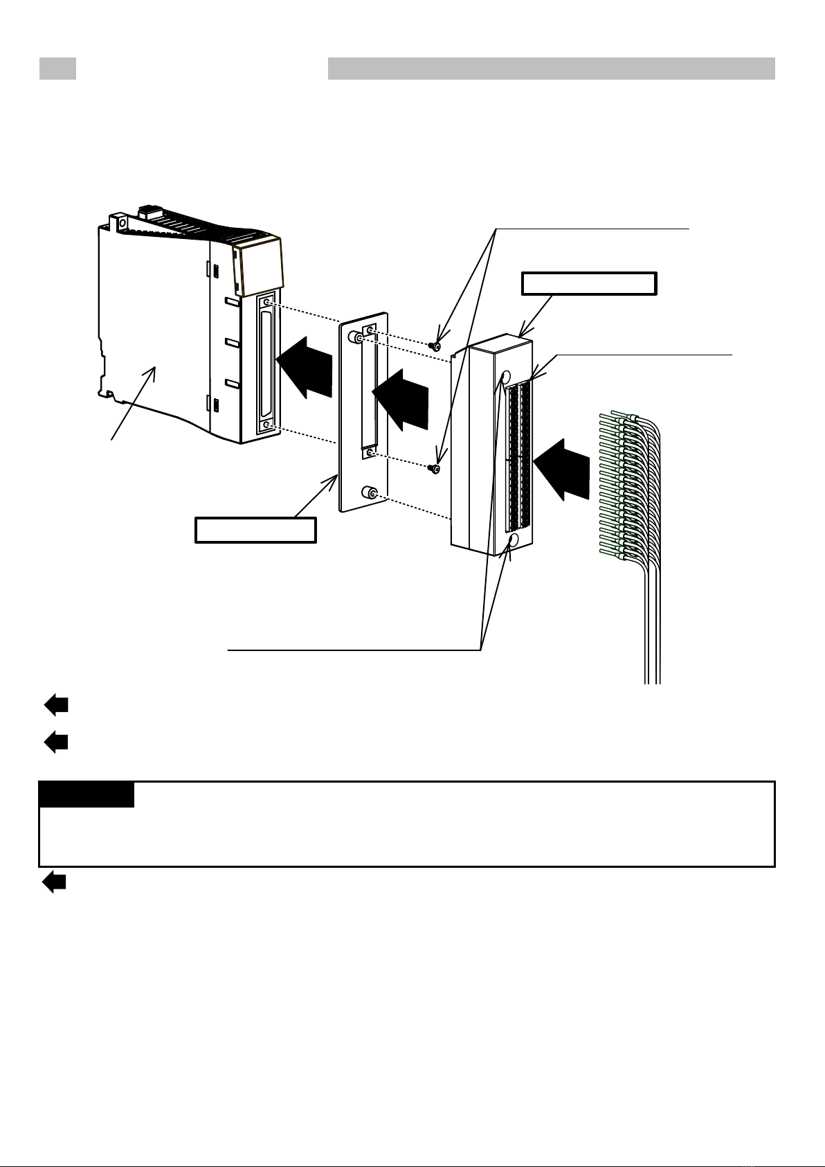
5-1. Connection to a programmable controller
Spring clamp terminal block
②
Conversion Adapter
Conversion adapter installation screw
M3×20
Mounting bracket
Programmable
controller
①
③
Mounting bracket fixing screw
M2.6×4
①Secure the mounting bracket to the Programmable Controller Module using the
Mounting bracket fixing screws(M2.6×4;2 upper/lower locations)
②Mount the Conversion Adapter onto the Mounting Bracket, and secure the Conversion Adapter
Using the Conversion Adapter installation screws (M3×20;2 locations)
Precaution
Before tightening the installation screws, check that the Conversion Adapter has been se
curely installed on the
Programmable controller.Tightening the screws in floating-off state or tilting state will damage the Conversion Adapter
installation screws and the Mounting Bracket.
③Install wires to the spring clamp terminal block.

12
5-2. Wiring to a spring clamp terminal block
(1) Wires routing
(a) Fabrication on cable insulator
Strip the wire as follows. If the length of the sheath peeled is too long, a short circuit may occur with
neighboring
wires. If the length is too short, wires might come off. Wire the stripped cable after twisting it to prevent it from
becoming loose. In addition, do not solder it.
(b) Using a ferrule terminal
Insert wires to a ferrule terminal and crimp it. Make sure that core wire slightly comes out of the ferrule.
Check the condition of the ferrule terminal after crimping. Do not use a ferrule terminal of which the crimping is
inappropriate, or the face is damaged.
Refer to chapter 9 for the applicable ferrule terminal.
* Ferrule terminals crimped onto one wire are applicable to the terminal block of this product.
If multiple wires need to be installed (such as for the power supply), provide an external common terminal.
(For example, ABCOM of a high-speed counter module or COM of a simple motion module)
8mm
13
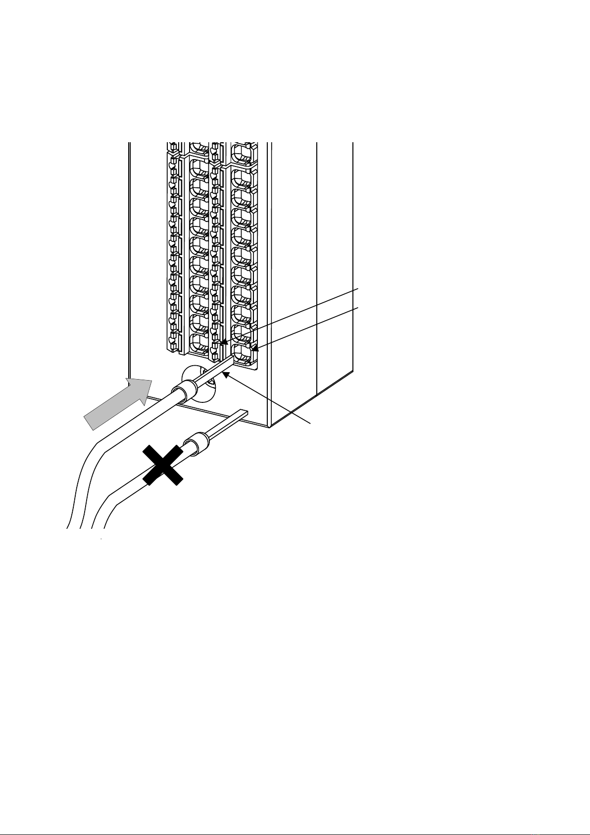
(c) Inserting wires
The wire with ferrule or solid cable can be inserted into the wire insertion hole. After
inserting, pull the wire lightly to confirm that the wire is surely connected.
For the correct terminal insertion direction, refer to the figure below.
When binding twisted wires, press the push button using the screw driver, then insert the twisted wires
into the wire insertion hole.
* Make sure to insert the wire straight and vertically as far as it will go.
(Push button)
Cable insertion hole
Ferrule terminals
14
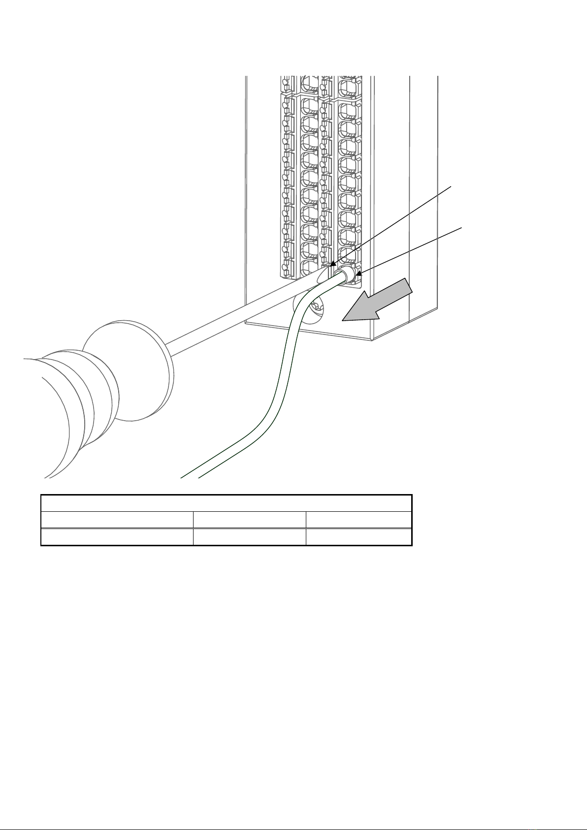
(2) Wires removal
Press the push button all the way using the screw driver, then pull out the wire.
(Push button)
Cable insertion hole
Use the screw driver shown in the table below.
Recommended tool (screw driver)
Manufacturer
Model
Blade edge size
PHOENIX CONTACT
SZS 0,4×2,5 VDE
2.5x0.4mm

15
6. INTERNAL WIRING DIAGRAM
Conversion Adapter
B20 A20
B19 A19
B18 A18
B17 A17
B16 A16
B15 A15
B14 A14
B13 A13
B12 A12
B11 A11
B10 A10
B9 A9
B8A8
B7A7
B6 A6
B5A5
B4 A4
B3 A3
B2 A2
B1 A1
A19
A20
A17
A18
A15
A16
A13
A14
A11
A12
A9
A10
A7
A8
A5
A6
A4
A2
A3
A1
B19
B20
B17
B18
B15
B16
B13
B14
B11
B12
B9
B10
B7
B8
B5
B6
B4
B2
B3
B1
40-pin connector
Spring clamp
terminal block
Pin No.
B20
B19
B18
B17
B16
B15
B14
B13
B12
B11
B10
B9
B8
B7
B6
B5
B4
B3
B2
B1
A20
A19
A18
A17
A16
A15
A14
A13
A12
A11
A10
A9
A8
A7
A6
A5
A4
A3
A2
A1
Pin No.
B20
B19
B18
B17
B16
B15
B14
B13
B12
B11
B10
B9
B8
B7
B6
B5
B4
B3
B2
B1
A20
A19
A18
A17
A16
A15
A14
A13
A12
A11
A10
A9
A8
A7
A6
A5
A4
A3
A2
A1
Rated current value
︓2.0A
︓0.5A

16
7. APPLICABLE SOLDERLESS TERMINALS(Ferrule)
Type
Applicable ferrule Crimp tool
Manufacturer
Applicable wire size
PHOENIX CONTACT
0.25/24
AI 0.25-8 YE
CRIMPFOX 6
0.3,0.34/22
AI 0.34-8 TQ
0.5/20
AI 0.5-8 WH
0.75/18
AI 0.75-8 GY
WAGO
0.08 to 0.34 mm
2
/AWG28 to 22
216-302
206-220
0.34 mm
2
/AWG24 and 22
216-302
206-1204,
206-204
0.5 mm
2
/AWG22 and 20
216-201
0.75 mm
2
/AWG20 and 18
216-202
17
8. CONNECTABLE MODULES
Module model for a programmable controller
Module model
MELSEC iQ-Rseries
Connector type
Input modules
RX41C4
RX41C6HS
RX71C4
RX61C6HS
FA1-TE40PA
Output modules
RY41NT2P
RY41PT1P
RY41NT2H
RY41PT2H
High-Speed Counter Module
RD62P2
RD62P2E
RD62D2
Positioning Module
RD75P2
Simple Motion Module
RD77MS2
MELSEC-Q series
Connector type
Input modules
QX41
QX41-S1
QX41-S2
QX71
Output modules
QY41P
QY41H
QY71
High-Speed Counter Module
QD62
QD62E
QD62D
QD63P6
QD64D2
Positioning Module
QD75P1/QD75P1N
QD75D1/QD75D1N
QD75P2/QD75P2N
QD75D2/QD75D2N
QD70P4
Simple Motion Module
QD77MS2
Servo external signals
interface module
Q172DLX/Q172LX
Manual pulse generator
interface module
Q173DPX/Q173PX/Q173PX-S1
MELSEC-L series
Connector type
Input modules
LX41C4
Output modules LY41NT1P
LY41PT1P
High-Speed Counter Module LD62
LD62D
Positioning Module
LD75P1
LD75D1
LD75P2
LD75D2
18
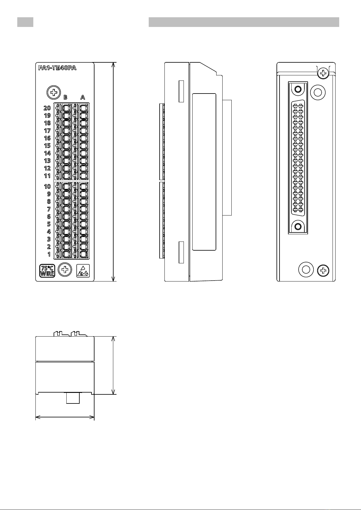
9. EXTERNAL DIMENSIONS
9-1. Spring Clamp Terminal Block Conversion Adapter (FA1-TE40PA)
[Unit︓mm]
27.4
27 102

19
9-2. Depth and height
[Unit︓mm]
MELSEC iQ-R ︓16.7
MELSEC-Q/L︓19.5
27

20
10. PRECAUTIONS
(1) For wiring to the terminal block, refer to the manual of the programmable controller module to be connected, published
by Mitsubishi Electric.
11. GRATIS WARRANTY TERMS AND GRATIS WARRANTY RANGE
If any fault or defect (hereinafter referred to as "Failure") attributable to Mitsubishi Electric Engineering should occur
within the gratis warranty period, Mitsubishi Electric Engineering shall replace the product free of charge via the
distributor from whom you made your purchase.
● Gratis warranty period
The gratis warranty period of this product shall be one (1) year from the date of purchase or delivery to the designated
place.
Note that after manufacture and shipment from MEE, the maximum distribution period shall be six (6) months, and
the gratis warranty period after manufacturing shall be limited to eighteen (18) months.
In addition, the gratis warranty period for repaired products shall not exceed the gratis warranty period established
prior to repair.
● Gratis warranty range
(1) The gratis warranty range shall be limited to normal use based on the usage conditions, methods and environment,
etc., defined by the terms and precautions, etc., given in the instruction manual, userʼs manual, and caution labels
on the product.
(2) In the following cases, a repair fee shall be applied even if within the gratis warranty period.
1) Failure resulting from inappropriate storage or handling, carelessness or negligence by the user, or Failure caused
by the user's hardware or software design.
2) Failure caused by unapproved modifications, etc., to the product by the user.
3) Failure that could have been avoided if, when the Mitsubishi Electric Engineering product was assembled into the
user's device, safeguards defined by legal regulations applicable to the user's device or functions or structures
considered standard by the industry had been provided.
4) Failure recognized as preventable if the consumed products specified in instruction manuals, etc., were normally
maintained or replaced.
5) Replacement of consumable parts (relays, etc.).
6) Failure caused by external factors beyond anyone's control such as fires or abnormal voltage, and Failure caused
by Force Majeure such as earthquakes, lightning, or wind and water damage.
7) Failure caused by reasons unpredictable by scientific technology standards at the time of shipment from Mitsubishi
Electric Engineering.
8) Any other failure not attributable to Mitsubishi Electric Engineering or found by the user to not be attributable to
Mitsubishi Electric Engineering.
12. EXCLUSION FROM LIABILITY FOR OPPORTUNITY LOSS AND SECONDARY LOSS
Regardless of the gratis warranty period, Mitsubishi Electric Engineering shall not be liable for compensation for damages
arising from causes not attributable to Mitsubishi Electric Engineering, opportunity losses or lost profits incurred by the
user due to Failures of Mitsubishi Electric Engineering products, damages or secondary damages arising from special
circumstances, whether foreseen or unforeseen by Mitsubishi Electric Engineering, compensation for accidents,
compensation for damages to products other than Mitsubishi Electric Engineering products, or compensation for
replacement work, readjustment of onsite machinery and equipment, startup test runs or other duties carried out by
the user.
13. TRADEMARKS
MELSEC, MELSEC iQ-R, CC-Link, CC-Link IE, and CC-Link/LT are trademarks or registered trademarks of Mitsubishi
Electric Corporation. Other company names and product names in the text are trademarks or registered trademarks of
each company.
In some cases, trademark symbols such as '™' or '®' are not specified in this manual.
Table of contents
Other MITSUBISHI ELECTRIC ENGINEERING Adapter manuals


