Mitsubishi Electric C10 SERIES User manual

®
HOME-THEATER TELEVISION
MODELS
638 Series
C10 Series
OWNER’S GUIDE
For questions:•
Visit our website at www.mitsubishi-tv.com.-
Call Consumer Relations at- 800-332-2119 for operational or connection assistance.
For information on• System Reset, please see the back cover.
To order replacement or additional remote controls or lamp cartridges, visit our website at•
www.mitsuparts.com or call 800-553-7278.

2
For assistance call 1(800) 332-2119
FCC Declaration of Conformity
Product: Projection Television Receiver
Models: WD-60638, WD-65638, WD-73638
WD-60C10, WD-65C10, WD-73C10
Responsible
Party:
Mitsubishi Digital Electronics
America, Inc.
9351 Jeronimo Road
Irvine, CA 92618-1904
Telephone: (800) 332-2119
This device complies with Part 15 of the FCC Rules.
Operation is subject to the following two conditions:
(1)
This device may not cause harmful interference,
and
(2) This device must accept any interference
received, including interference that may cause
undesired operation.
Note: This equipment has been tested and found
to comply with the limits for a Class B digital device,
pursuant to part 15 of the FCC Rules. These limits
are designed to provide reasonable protection
against harmful interference in a residential instal-
lation. This equipment generates, uses and can
radiate radio frequency energy and, if not installed
and used in accordance with the instructions, may
cause harmful interference to radio communica-
tions. However, there is no guarantee that interfer-
ence will not occur in a particular installation. If this
equipment does cause harmful interference to radio
or television reception, which can be determined
by turning the equipment off and on, the user is
encouraged to try to correct the interference by one
or more of the following measures:
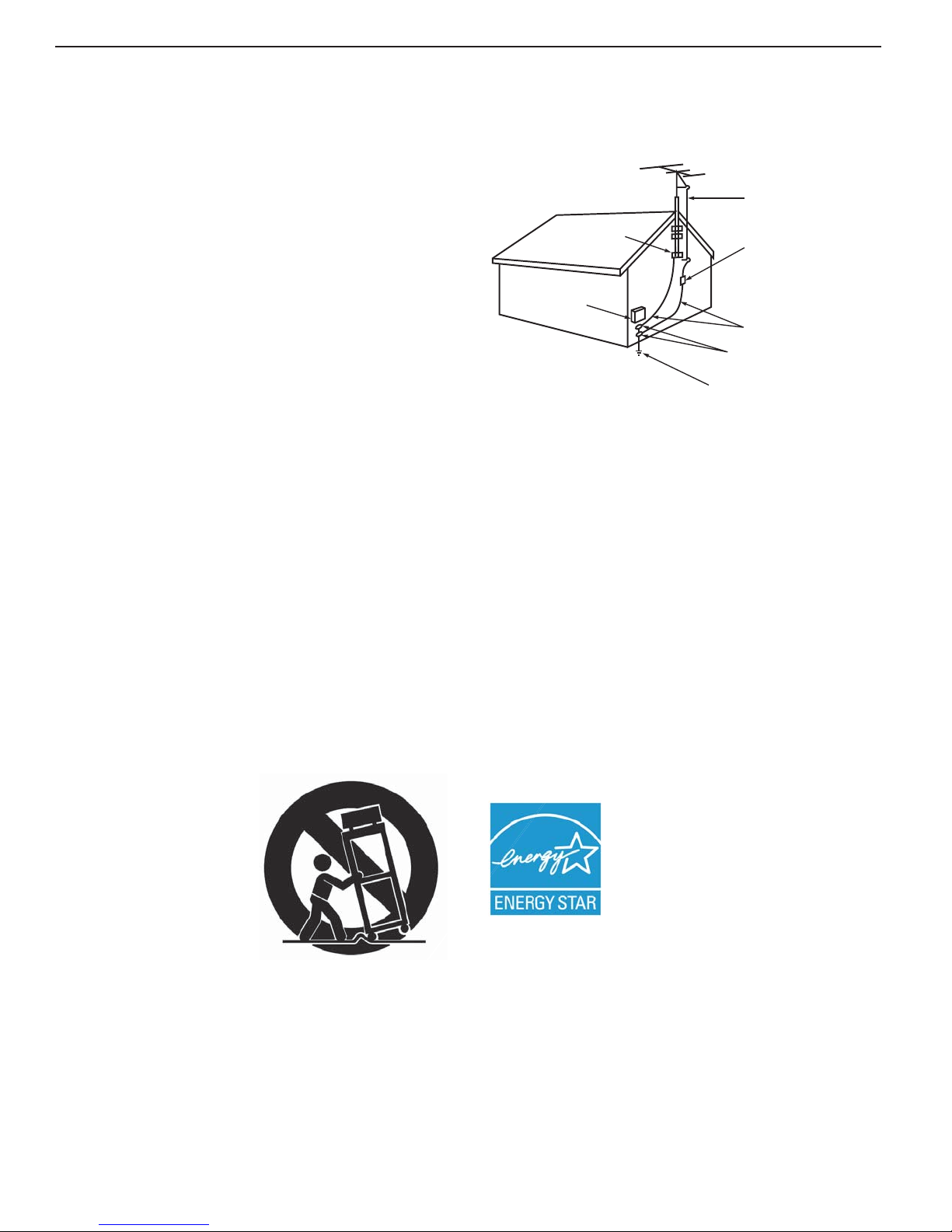
Reorient or relocate the receiving antenna.-
Increase the separation between the equip--
ment and the receiver.
Connect the equipment into an outlet on-
a circuit different from that to which the
receiver is connected.
Consult the dealer or an experienced radio/-
TV technician for help.
Changes or modifications not expressly
approved by Mitsubishi could cause harmful
interference and would void the user’s authority
to operate this equipment.
CAUTION
RISK OF ELECTRIC SHOCK
DO NOT OPEN
CAUTION: TO REDUCE THE RISK OF ELECTRIC
SHOCK, DO NOT REMOVE COVER (OR BACK).
NO USER SERVICEABLE PARTS INSIDE. REFER
SERVICING TO QUALIFIED SERVICE PERSONNEL.
TV WEIGHT: This TV is heavy. Exercise extreme care
when lifting or moving it. Lift or move the TV with a
minimum of two adults. To prevent damage to the TV,
avoid jarring or moving it while it is turned on. Always
power off your TV, unplug the power cord, and discon-
nect all cables before moving it.
WARNING: To reduce the risk of fire or electric shock,
do not expose this apparatus to rain or moisture.
This apparatus shall not be exposed to dripping or
splashing and no objects filled with liquids, such as
vases, shall be placed on the apparatus.
WARNING: This product contains chemicals known
to the State of California to cause cancer and/or birth
defects or other reproductive harm.
Note: Features and specifications described in this
owner’s guide are subject to change without notice.
MAINS DISCONNECTION: The mains plug is used
as the disconnect device. The mains plug shall remain
readily operable.
Stand Requirement
CAUTION: Use these Mitsubishi TV models only with
the Mitsubishi stand models shown here. Other stands
can result in instability and possibly cause injury.
TV Model Stand Model
WD-60638, WD-65638
WD-60C10, WD-65C10 MB-S60/65A
WD-73638
WD-73C10 MB-S73A
The lightning flash with arrowhead symbol
within an equilateral triangle is intended to
alert the user of the presence of uninsulated
“dangerous voltage” within the product’s
enclosure that may be of sufficient magnitude to consti-
tute a risk of electric shock to persons.
The exclamation point within an equilat-
eral triangle is intended to alert the user to
the presence of important operating and
maintenance (servicing) instructions in the
literature accompanying the product.

3
For assistance call 1(800) 332-2119
Contents
1 Setup and Operation
Getting Started ......................... 5
TV Controls ............................ 6
The STATUS Indicator ..................... 7
TV Inputs.............................. 8
Picture Settings ......................... 8
Using an External Sound System ............. 8
The FORMAT Key and Picture Shape .......... 9
FAV (Favorite Channels)................... 10
Using the TV with a Personal Computer ....... 11
Status Display ......................... 12
3D Video ............................. 13
2 TV Connections
Connection Panel ....................... 15
Connection Types and Audio/Video Quality .... 16
H
DMI Device .............................17
DVI Video Device ....................... 17
Y Pb Pr Component Video Device ........... 17
Composite Video Device .................. 17
Antenna or Cable TV Service ............... 18
VCR or DVD Recorder to an Antenna or
Wall Outlet Cable ...................... 18
A/V Receiver with Coaxial Input............. 18
A/V Receiver with HDMI Output............. 19
3 TV Menus
Picture............................... 20
Sound ............................... 21
Setup ............................... 21
Channels ............................. 23
Locks ............................... 24
Appendices
Appendix A: TV Care
Lamp-Cartridge Replacement ........... 27
Cleaning Recommendations ............ 29
Care of the Remote Control ............. 29
Appendix B: Troubleshooting .............. 30
Trademark and License Information .......... 33
Warranty .............................. 38
Custom cabinet installation must allow for proper
air circulation around the television.
NOTE TO CATV SYSTEM INSTALLER: THIS REMINDER
IS PROVIDED TO CALL THE CATV SYSTEM INSTALLER’S
ATTENTION TO ARTICLE 820-40 OF THE NEC THAT PRO-
VIDES GUIDELINES FOR THE PROPER GROUNDING AND,
IN PARTICULAR, SPECIFIES THAT THE CABLE GROUND
SHALL BE CONNECTED TO THE GROUNDING SYSTEM OF
THE BUILDING, AS CLOSE TO THE POINT OF CABLE ENTRY
AS PRACTICAL.
Internal Fans
Internal cooling fans maintain proper operating tem-
peratures inside the TV. It is normal to hear the fans
when you first turn on the TV, during quiet scenes
while viewing the TV, and for a short time after shutting
off the TV. You may notice louder fan noise about 30
seconds after shutting off the TV.
Lamp Replacement
For lamp-replacement instructions, see Appendix A.
To Order a Replacement Lamp Under Warranty
Call (800) 553-7278. Please have model number, serial
number, and TV purchase date available.
Important: All lamps replaced under warranty
must be returned to Mitsubishi where they will be
inspected to verify failure defects.
To Purchase a Replacement Lamp After Warranty
Visit our website at www.mitsuparts.com or call (800)
553-7278. Order new lamp part number 915B441001.
TV Software
Do not attempt to update the software of this TV with
software or USB drives not provided by or authorized
by Mitsubishi Digital Electronics America, Inc. Non-
authorized software may damage the TV and will not be
covered by the warranty.
Children and TV Viewing
The American Academy of Pediatrics discourages
television viewing for children younger than two years of
age.
For Your Records
Record the model number, serial number, and
purchase date of your TV. The model and serial
numbers are on the back of the TV. Refer to this
page when requesting assistance with the TV.
MODEL NUMBER
SERIAL NUMBER
PURCHASE DATE
RETAILER NAME
LOCATION

4
For assistance call 1(800) 332-2119
Important Safety Instructions
Please read the following safeguards for your TV and
retain for future reference. Always follow all warnings
and instructions marked on the television.
1) Read these instructions.
2) Keep these instructions.
3) Heed all warnings.
4) Follow all instructions.
5) Do not use this apparatus near water.
6) Clean only with dry cloth.
7) Do not block any ventilation openings. Install in
accordance with the manufacturer’s instructions.
8) Do not install near any heat sources such as
radiators, heat registers, stoves, or other apparatus
(including amplifiers) that produce heat.
9) Do not defeat the safety purpose of the polarized
or grounding-type plug. A polarized plug has two
blades with one wider than the other. A grounding
type plug has two blades and a third grounding
prong. The wide blade or the third prong are
provided for your safety. If the provided plug does
not fit into your outlet, consult an electrician for
replacement of the obsolete outlet.
10) Protect the power cord from being walked on
or pinched particularly at plugs, convenience
receptacles, and the point where they exit from the
apparatus.
11) Only use attachments/accessories specified by the
manufacturer.
12) Use only with the cart,
stand, tripod, bracket,
or table specified
by the manufacturer,
or sold with the
apparatus. When
a cart is used, use
caution when moving
the cart/apparatus
combination to avoid
injury from tip-over.
13) Unplug this apparatus
during lightning storms or when unused for long
periods of time.
14) Refer all servicing to qualified service personnel.
Servicing is required when the apparatus has been
damaged in any way, such as power-supply cord or
plug is damaged, liquid has been spilled or objects
have fallen into the apparatus, the apparatus has
been exposed to rain or moisture, does not operate
normally, or has been dropped.
ANTE NNA
LEAD IN WIRE
ANTE NNA
DIS CHAR G E UNIT
(NE C AR TICLE 810-20)
GROUNDING
CONDUCTORS
(NEC ARTICLE 810-21)
GROUND CLAMPS
POWER SERVICE GROUNDING
ELECTRODE SYSTEM
(NE C AR T 250, P AR T H)
GROUND CLAMP
ELECTRIC
SERVICE
EQUIPMENT
NEC —NATIONAL ELECTRICAL CODE
EXAMPLE OF ANTENNA GROUNDING
Outdoor Antenna Grounding
If an outside antenna or cable system is connected
to the TV, be sure the antenna or cable system is
grounded so as to provide some protection against
voltage surges and built-up static charges.
Replacement Parts
When replacement parts are required, be sure the
service technician has used replacement parts speci-
fied by the manufacturer or have the same character-
istics as the original part. Unauthorized substitutions
may result in fire, electric shock or other hazards.
The following TV models are
ENERGY STAR®qualified:
WD-65638, WD-73638
WD-65C10, WD-73C10
Products that earn the ENERGY
STAR prevent greenhouse gas
emissions by meeting strict energy
efficiency guidelines set by the U.S.
Environmental Protection Agency
and the U.S. Department of Energy.

5
For assistance call 1(800) 332-2119
Setup and Operation
1
Remote Control
Two AA Batteries AA
AA
Owner’s Guide
Quick Setup Guide
Product Registration
Card
Package Contents
Please take a moment to review the following list of
items to ensure that you have received everything.
Installing the Remote Control
Batteries
Remove the remote control’s back cover by gently
1.
pressing on the tab and lifting off the cover.
Load the batteries, making sure the polarities
2.
(+) and (-) are correct. For best results, insert
the negative (-) end first.
Snap the cover back in place.
3.
2
1The remote
control requires
two AA
batteries.
Before You Power on the TV
Review the important safety, installation, and oper-
1.
ating information at the beginning of this book.
Choose a location for your TV.
2.
• Allow at least four inches of space on all sides
of the TV to help prevent overheating. Over-
heating may cause premature failure of the TV
as well as shortened lamp life.
• Avoid locations where light may reflect off the
screen.
• See the stand requirements on page 2.
Install the batteries in the remote control.
3.
Plug the TV into an AC power outlet.
4.
First-Time Power-On
Connect your devices to the TV.
1.
See• page 15 for suggestions.
If using an antenna or direct cable service (no•
cable box), connect the incoming coaxial cable
to the TV’s
ANT
input. Refer to page 18.
Make note of which device is connected to•
each TV input.
Power on the TV.
2.
Aim the emitter end of the remote at the TV and
press
POWER
.
Follow the on-screen instructions for basic
3.
setup:
a. Select a menu language.
b. Select your time zone.
c. Select Yes or No for Daylight Saving Time.
d. Select the source connected to the TV’s
ANT
input jack, either an over-the-air antenna or
direct cable service without a box. Skip this
step if nothing is connected.
e. Perform a channel scan for channels available
from the
ANT
input.
f. Wait a few moments for the screen to clear.
Getting Started

61. Setup and Operation
For assistance call 1(800) 332-2119
Remote Control
Powers TV on or off.
Number/letter keys
Channel tuning, page 8
PIN entry, page 24
Sleep Timer. Turns off the TV after the length
of time you set. Press
SLEEP
repeatedly to
increase the time from 15 minutes up to the
maximum of 90 minutes. To cancel the timer,
press
SLEEP
again to highlight Off.
Emitter End
INFO
TV status, page 12
MUTE
Mutes the TV speakers.
VOL
/ Controls volume of TV speakers.
CH
/ Changes channels
Adds a separator in digital channel
numbers. Clears some menu entries.
AUDIO
Digital Source: Switches
between language tracks avail-
able for the current program.
To change the default, use the
Sound > Language menu.
Analog Source: Switches
between Mono, Stereo, and
SAP for the current program.
To change the default, use the
Sound > Analog Listen To
menu (page 21).
MENU
Displays or clears the TV main
menu (page 20).
Also steps
back one menu.
LAST
Returns to the previous channel.
Navigation and adjustment
controls
ENTER
Press to confirm a selection
.
FAV
Displays up to nine favorite
channels, page 10.
FORMAT
Changes picture shape,
page 9
FREEZE
Freezes a broadcast TV
picture.
INPUT
Press to select a TV input.
See “TV Inputs” page 8.
TV Controls
If You Power Off the TV by Mistake
If the status indicator is green and blinking
rapidly, (about 60 seconds after you shut off
power), wait a few moments for the status indi-
cator to stop blinking and press
POWER
to turn
the TV on again.
VIDEO
Selects a
Picture Mode,
page 20
EXIT
Clears all menus.
Note
The following keys are not used in this model:
TOOLS
GUIDE

1. Setup and Operation 7
For assistance call 1(800) 332-2119
TV Controls, continued
TV Control Panel
Buttons on the control panel duplicate some keys on
the remote control.
Refer to• lower labels when using TV menus or after
activating a special function.
Refer to• upper labels when no TV menus are dis-
played.
SYSTEM RESET.• If the TV does not respond to the
remote control, control-panel buttons, or will not
power on/off, press and hold the
POWER
button on
the control panel for ten seconds.
The STATUS Indicator
Key Off Steady On
Slow Blinking Fast Blinking
LED Color TV Condition
None TV is powered off. Normal operation.
Green TV is powered on. Normal operation.
Green TV powered off, auto-on TV Timer is set.
Normal operation. TV can be turned on at any time.
Green TV just powered off and lamp is cooling.
Sixty seconds after turning off TV, LED will start to blink. TV can be turned back on before blinking
starts or after blinking stops, but not while the indicator is blinking. Normal operation.
Amber TV is too hot.
The TV will shut off if it overheats.
• Ambient room temperature may be too high. Turn off the TV and let the room temperature drop.
• Clear blocked air vents. Ensure at least a four-inch clearance on all sides of the TV.
Amber Lamp access door is not secure or no lamp installed.
TV will not operate until lamp access door is secured. See Appendix A.
Red Lamp failure. Replace the lamp. See Appendix A.
Red/
Amber
TV may require service.
Hold power button on front panel for 10 seconds to reset TV.•
If LED continues to flash red and amber after reset, turn off the TV and unplug it from the AC•
power source. Wait one minute and then plug the set back in.
If LED continues to flash red and amber,•
go to www.mitsubishi-tv.com or call 1-800-332-2119 to
receive Authorized Service Center information.
You may be asked to count how many times the LED flashes each color to aid in troubleshooting.
65” or 73” TV: Open
cover to use buttons
on the front panel.
POWER
STATUS
INPUT
Typical
control
panel.

81. Setup and Operation
For assistance call 1(800) 332-2119
Tuning Channels from the Antenna Input
After performing a channel scan, use these methods to
tune to channels on the
ANT
input. Channels can be
either from an over-the-air antenna or from direct cable
service.
Enter the channel number using the number keys•
on the remote control and press
ENTER
.
Include the sub-channel when tuning digital chan-•
nels. For a two-part digital channel, such as 3-1,
press 3
—
CANCEL
1
ENTER
.
Press• CH / to change channels one channel
at a time.
Press and hold• CH / to speed through chan-
nels.
Press•
LAST
to return to the previous channel.
Use the Fav (Favorites) feature to tune to up to nine•
favorite channels. See page 10.
Using an External Sound System
To switch from the internal TV speakers to an external
sound system:
Press
1.
MENU
.
Display the
2.
Sound > TV Speaker option.
Press
3.
ENTER
to switch between ON and OFF..
Additional audio controls are in the Sound menu, page
21.
Picture Settings
To get the best picture under dif-
1.
ferent viewing conditions, set the
Picture Mode first before changing
other video settings. See page 20 .
a. Press
VIDEO
multiple times to select
one of these Picture Modes:
Name When to Use
Brilliant
Under bright light
Bright For most daytime viewing
Natural For most nighttime viewing
Game
With gaming consoles
b. Press
ENTER
to confirm your selection.
Wait a few seconds for
2.
the display to clear.
Additional picture options are available in the Picture
menu, page 20.
Naming
Assign helpful names to TV inputs.
Press
1.
MENU
.
Go to the
2.
Setup > Input > Input Name menu.
In the inputs list, highlight the input to change and
3.
press
ENTER
.
Highlight a name in the name list.
4.
Press
5.
ENTER
to confirm
the name.
Press
6.
EXIT
to clear
menus.
Removing
To remove unused inputs from the input list,
Switch to an input other than the one you are
1.
removing.
Go to the name list for the input as described
2.
above.
Highlight
3.
Skip this input and press
ENTER
.
Press
4.
EXIT
to clear menus.
Selecting an Input to Watch
Press the
INPUT
key to select a TV input to watch. Use
the Setup > Input menu to rename, add, or remove
inputs from the list.
TV Inputs

1. Setup and Operation 9
For assistance call 1(800) 332-2119
The FORMAT Key and Picture Shape
Important
Black bars at the edges of the
picture are common in HD
pictures. Black bars are not a
defect of the TV.
Black bars are added by broad-•
casters to fill the 16:9 screen
area while preserving the original
aspect ratio of the picture.
Your cable box, satellite receiver,•
or DVD player may also be alter-
ing the broadcast picture. If your
device offers output in native
format, try using it with Mitsubi-
shi’s picture formats.
Sample Uses of the
FORMAT
Key
You can use the
FORMAT
key to reduce or eliminate black areas at the
picture edges.
Press
Squarish 4:3 image is
narrower than the 16:9
screen; unused areas at the
sides are filled with black.
Standard mode stretches the
picture sideways to fill the
screen.
Press
Wide 2.35:1 anamorphic DVD
image; unused areas at the
top and bottom are filled with
black (letterbox effect).
Zoom mode. The picture fills
the screen. All four edges are
cropped in this mode.
Repeatedly press the
FORMAT
key to cycle
through displays avail-
able for the current
program. The TV will
remember the format
you last used on each
input.
TV Signals and Display Formats
This is a 16:9 widescreen TV suitable for images available
from HDTV and many DVDs. You can view older-style,
squarish images (4:3 aspect ratio) using one of the display
formats described on this page (press the
FORMAT
key to
cycle through available display formats).
All high-definition channels send widescreen (16:9)
signals, but not all programming was created for the
widescreen format. The broadcaster may stretch the
image or add side bars to fill the widescreen area.
TV Display Format Definitions
Standard: The full-screen format used by HDTV
signals. Use this format to display anamorphic DVDs
with a 1.78:1 or 1.85:1 aspect ratio. Anamorphic DVDs
with a 2.35:1 aspect ratio are displayed correctly but
with top and bottom black bars. Squarish (4:3) images
are stretched evenly from side to side. Available for all
signals.
Expand: Enlarges the picture to fill the screen by
cropping the top and bottom; useful for reducing the
letter box top and bottom bars of non-anamorphic DVD
images.
Zoom: Enlarges the picture to fill the screen by crop-
ping the sides, top, and bottom to eliminate black bars.
480i/480p and SD 4:3 signals:• Eliminates top and
bottom bars on anamorphic DVDs with a 2.35:1
aspect ratio.
720p, 1080i, SD 16:9, and HD signals:• Eliminates
bars added to squarish 4:3 images.
Stretch: Stretches a squarish 4:3 image across the
screen to display the entire image with less distortion
than the Standard format.
Narrow: Displays narrow 4:3 images in their original
shape. Adds black side bars to fill the screen.
Wide Expand: Enlarges the picture, cropping the
image on both sides. Removes or reduces black side
bars added to narrow images converted to 16:9 signals
for digital broadcast.
Using the FORMAT Key

10 1. Setup and Operation
For assistance call 1(800) 332-2119
Non-anamorphic or SD 4:3
Anamorphic DVD
Standard
Distorted.
Not recom-
mended.
Recommended
Expand
Recom-
mended for
letterbox. See
Note 1.
Distorted; not
recommended.
See Note 1.
Zoom
Distorted.
Not recom-
mended. See
Note 1.
Recommended
for anamorphic
2.35:1 images.
See Note 1.
Stretch
Recom-
mended for
standard
broadcasts.
See Note 1.
Distorted; not
recommended.
See Note 1.
Narrow
See Note 1 Distorted; not
recommended.
See Note 1.
Note 1: Available for 480i, 480p, and digital SD 4:3 signals only.
Original Signal Display Formats
SD 16:9 or
HD Digital
720p, 1080i,
1080p Signal
Wide
Expand
Recommended to re-
move side bars.
Zoom
Recommended to re-
move bars from the top,
bottom, and sides.
TV Display Formats. Press the
FORMAT
key
to see the
displays available for the current program.
Original
Signal
TV
Display
Summary of Mitsubishi Display Formats
TV Signals and Display Formats,
continued
DVD Image Definitions
Image information may be stated on the DVD case.
Some DVDs support both of the formats described
below.
Anamorphic (or Enhanced for WideScreen TV)
Indicates DVDs recorded to show widescreen images
properly on 16:9 TV sets using the TV’s Standard
format mode (recommended).
Non-Anamorphic (or 4:3, 1.33:1, Letter Box, or
Full Screen)
Indicates DVDs recorded for viewing on squarish TV
screens. They may be full screen (4:3 or 1.33:1) which
crops movies to fit the narrow TV, or letter box, which
adds black top and bottom bars.
FAV (Favorite Channels)
Favorite Channels and the
Remote Control
The
FAV
key gives you quick access to
favorite channels from the antenna input.
You can store up to nine favorite channels.
Adding
Switch to the antenna1.
input (press
INPUT
and
select Antenna).
Tune to the channel.2.
Press the3.
FAV
key.
With the desired4.
channel highlighted,
highlight Add and press
ENTER
.
Removing
While using the antenna input, press the1.
FAV
key.
In the2. Favorites menu, highlight the channel to
remove.
Highlight3. Remove and press
ENTER
.
Tuning
Method 1
While watching TV, press the1.
FAV
key.
Highlight the channel number in the list and2.
press
ENTER
.
Method 2
While watching TV, repeatedly press the
FAV
key to
cycle through channels in the FAV list.
The Favorites Menu
Press
1.
MENU
and go to Channels > Favorites.
Highlight the channel you want to add or remove.
2.
Tip: To jump to a channel, enter the channel
number, including separator, and press
ENTER
.
Example: 361
ENTER
.
Press
3.
ENTER
to add/remove a check. You can
select up to nine favorite channels.
Highlight
4.
DONE and press
ENTER
to finish.

1. Setup and Operation 11
For assistance call 1(800) 332-2119
Using the TV with a Personal Computer
Tip
Set the computer’s screen saver to display a
screensaver pattern after several minutes of inactiv-
ity. This acts as a reminder that the TV is powered
on and the lamp is in use. The lamp is in use
whenever the TV is powered on, even if the screen
appears dark.
Computer Video Adjustments
Working from the computer, change the resolution
1.
of the computer image. View the computer image
on the TV and maximize the computer resolution
while maintaining a suitable aspect ratio for the
image.
Perform TV video adjustments in the
2.
Setup >
Picture menu.
Press the
3.
FORMAT
key repeatedly to find the picture
format best suited to the image. See the chart on
the next page showing how different computer
resolutions can be displayed on the TV.
Image Resolution
Your Mitsubishi TV can display the resolutions shown
in the chart on the next page from standard VGA (640 x
480) through 1920 x 1080 signals at a refresh rate of 60
Hz.
In most cases, the computer will select the best resolu-
tion match to display on the TV. You can override this
setting if you wish. Refer to your computer operating
system’s instructions for information on changing the
screen resolution.
You may need to restart the computer for changes to
take effect.
Distortion in Computer Images
Computer images may show distortion when
viewed on the TV, e.g., lines that should be straight
may appear slightly curved.
Connecting a Computer to the TV
Use one of the connection methods listed below based
on your computer’s video output.
Computer
Video Output
Video Connection Audio
Connection
Digital
DVI
DVI-to-HDMI cable or
an HDMI cable with a
DVI-to-HDMI adapter
See “DVI Video
Device,” page 17.
Analog audio
cable with mini
plugs
HDMI HDMI-to-HDMI cable
See “HDMI Device,”
page 17.
No additional
audio connec-
tion is required.
IMPORTANT
This TV accepts digital computer
video signals only. This TV is not
compatible with VGA (analog)
computer video.
VGA
PC MONITOR OUT
Connect the computer’s digital signal output to one
1.
of the TV’s HDMI jacks. See the connection dia-
grams for the method suited to your equipment.
Connect the computer’s audio output using one of
2.
these options:
• For digital DVI video signals, connect the
analog audio output to the TV’s
DVI/PC AUDIO
INPUT
jack.
• For HDMI signals, no additional audio connec-
tion is required.
• If your computer provides digital audio output
(coaxial or optical), connect it directly to a
digital A/V receiver and bypass the TV.
Power on the TV and computer.
3.
Go to the TV’s
4.
Setup > Input > Input Name menu
and assign the name PC.
To switch the TV to the computer, press the
5.
INPUT
key and select PC from the inputs list.
Note: If you are unable to hear audio from the
computer, there may be an incompatibility in
the computer’s hardware, software, or internal
settings. Consult a trained computer technician
for advice.

12 1. Setup and Operation
For assistance call 1(800) 332-2119
Press the
INFO
key to see an
abbreviated status display.
Press
INFO
again to see
details. Not all information
shown in the sample will be
available for all programs
and sources.
Basic Status Display
1. Channel number. Digital channel includes major
and sub-channel numbers.
2. Digital channel name (if broadcast)
3. Program start time (if broadcast, digital source
only)
4. Program name (if broadcast); digital source only
5. Day and time (set clock in the Setup > Clock
menu).
Detailed Status Display
Press
INFO
a second time to see details.
6. Signal-strength indicator (digital signal, antenna
only)
7. Signal type being received. See “Signal Defini-
tions” on this page.
8. Program audio indicator (antenna source only)
9. Program description (if broadcast); digital source
only.
10. V-Chip rating, closed-captions indicator,
program signal type (if broadcast)
Status Display
5
9
INFO
810
2 3 4
Signal Definitions
480i: Standard-definition interlaced signals
480p: Progressive-scan enhanced-definition signals
HD 1080i and HD 720p: High-definition 16:9 (wide-
screen) signals.
HD 1080p: High-definition signals from a PC or Blu-ray
player, HDMI inputs only.
Computer Display Formats
Press the
FORMAT
key repeatedly to cycle through the
displays available for your computer’s video signal.
Computer Signal
As Displayed on TV Screen
Original Format 4 X 3
Standard
16 X 9
Standard Zoom
VGA
640 X 480
SVGA
800 X 600
Original Format Standard Zoom
XGA
1024 X
768
PC 720p
1280 X
720
WXGA
1360 X
768
Original Format Standard Reduce
PC 1080p
1920 X
1080
Using the TV with a Personal
Computer, continued
1
6
7

1. Setup and Operation 13
For assistance call 1(800) 332-2119
3D Video
Notice Concerning Format Compatibility
In order to display 3D images. Mitsubishi 3D Ready DLP
Home Cinema TVs require the use of a 3D source device
coupled with the Mitsubishi 3D adapter or other source
devices that support checkerboard display formats for
display of 3D games, 3D broadcasts from terrestrial/cable/
satellite and 3D Blu-Ray disc content. In all cases an emitter
and matching 3D active shutter glasses or DLP Link active
shutter glasses are required in order to view 3D content.
To display 3D gaming or 3D cinema content, your
Mitsubishi TV requires:
A compatible 3D source device outputting a 3D•
signal in checkerboard format, 1080p, 60-Hz; lower
resolutions may be supported but will not fill the
screen.
Active-shutter 3D glasses, DLP link type or IR•
emitter type with matching emitter.
Initial Setup
If your 3D glasses came with an emitter, connect
1.
the emitter to the
3D GLASSES EMITTER
jack. Place
the box in front of the TV where there is a clear path
to the glasses.
Notes:
• If you require a Mitsubishi 3D adapter, refer
to the connection instructions provided with
the adapter. Please check our website,
www.mitsubishi-tv.com for updates to 3D
information and safety.
• If your glasses are marked DLP Link, skip
this step; no emitter is required with DLP
Link technology.
123
HDMI
HDMI
Pb Pr
INPUT 2
INPUT 1
(480i / 480p / 720p / 1080i)
Y/ VIDEO
Pb Pr
Y/ VIDEO
3D
GLASSES
EMITTER
ANT
AUDIO
LR
DIGITAL
AUDIO
OUTPUT
DVI/PC
AUDIO
INPUT
3D
GLASSES
EMITTER
Connect the 3D video device to the TV’s HDMI
2.
input.
Watching 3D Video
Note: Active 3D glasses are required.
Connect your 3D video device to one of the TV’s
1.
HDMI inputs and power on the device.
Press
2.
INPUT
.
Highlight the 3D video input and press
3.
ENTER
to
switch to it.
Press
4.
MENU
and select the Setup > 3D Mode
menu.
Highlight
5.
3D Mode and press
ENTER
to select On.
The On setting will be memorized for the current
input when you exit this menu.
If using DLP Link-type glasses, highlight
6.
DLP Link
and press
ENTER
to select ON.
Use the Setup > 3D Mode menu to enable 3D video.
Press
7.
EXIT
to close the menu.
If the image does not appear correct
8.
(e.g., objects
appear to be moving in instead of out),
open the Setup
> 3D Mode menu and highlight 3D Mode Glasses
L-R. Press
ENTER
to change to Reverse.
To Watch Regular (non-3D) Video
The 3D Mode setting is memorized for each input.
When you want to watch non-3D video on the input
selected above, open the Setup > 3D Mode menu and
set 3D Mode to Off.

14 1. Setup and Operation
For assistance call 1(800) 332-2119
3D Video, continued
3D Safety Requirements
3D Glasses are NOT designed as sunglasses or•
safety glasses and do not provide protection. 3D
glasses should be worn only when viewing 3D
material.
Do not wear the wireless glasses in any situations•
that require unimpaired visual perception.
Chi• ldren under the age of 5 should not view 3D
programming.
Under normal conditions, 3D viewing is safe for your
movies or games. Some people may experience dis-
comfort, however. To minimize the potential for experi-
encing visual problems or any adverse symptoms:
Read and follow any and all safety warnings that•
accompany your 3D glasses or 3D source devices.
Maintain a distance of no less than 2 to 2.5 times•
the screen height measurement away from the
display. Viewing from too short a distance can
strain your eyes.
Take regular breaks, at least 5 minutes after every•
hour of 3D viewing.
If you experience any of the following symptoms, dis-
continue 3D viewing until the symptoms go away:
nausea, dizziness, or queasiness,•
headache, or eyestrain,•
blurry vision,•
d• ouble vision that lasts longer than a few seconds,
Do not engage in any potentially hazardous activity
(for example, driving a vehicle) until your symptoms
have completely gone away. If symptoms persist,
discontinue use and do not resume 3D viewing without
discussing your symptoms with a physician.
Do not use the glasses where loss of balance or limit-
ing your field of vision may be dangerous to you.
Do not use near staircases, ledges or balconies. You
may risk falling during or after use.
Epilepsy
WARNING! IF YOU OR ANY MEMBER OF YOUR
FAMILY HAS A HISTORY OF EPILEPSY, CONSULT
A PHYSICIAN BEFORE USING 3D VIDEO OR GAME
PRODUCTS.
A small percentage of the population may experience
epileptic seizures when viewing certain types of TV
images or video games that contain flashing patterns of
light.
The following people should consult a physician before
viewing 3D Games or Video:
Any• one with a history of epilepsy, or who has a
family member with a history of epilepsy
Anyone who has ever experienced epileptic sei-•
zures or sensory disturbances triggered by flashing
light effects.
WARNING! SOME LIGHT PATTERNS MAY INDUCE
SEIZURES IN PERSONS WITH NO PRIOR HISTORY
OF EPILEPSY. DISCONTINUE 3D VIEWING IF YOU
EXPERIENCE ANY OF THE FOLLOWING SYMP-
TOMS:
Invol• untary movements, eye or muscle twitching
Muscle cramps•
Nausea, dizziness, or queasiness•
Convulsions•
Diso• rientation, confusion, or loss of awareness of
your surroundings
Do not engage in any potentially hazardous activity (for
example, driving a vehicle) until your symptoms have
completely gone away.
Do not resume 3D viewing without discussing the
symptoms with your physician.

15
For assistance call 1(800) 332-2119
2TV Connections
123
HDMI
HDMI
Pb Pr
INPUT 2
INPUT 1
(480i / 480p / 720p / 1080i)
Y/ VIDEO
Pb Pr
Y/ VIDEO
3D
GLASSES
EMITTER
ANT
AUDIO
LR
DIGITAL
AUDIO
OUTPUT
DVI/PC
AUDIO
INPUT
HDMI
(page 17)
DVI/PC AUDIO
INPUT
(page 17)
DIGITAL AUDIO
OUTPUT
(page 18)
R & L
Analog
Audio
Input
Y Pb Pr
(component
video)
ANT
(page 18)
3D GLASSES EMITTER
(page 13)
Connection Panel
Y/VIDEO
(composite
video)
USB
For use by your
TV servicer
1 83
6
4
5
2
7
1. ANT (Antenna)
Connect your main antenna or direct cable service (no
cable box) to
ANT
. The
ANT
input can receive digital
and analog over-the-air channels from a VHF/UHF
antenna or non-scrambled digital/analog cable source.
2. Right and Left Analog Audio Inputs
Use with
INPUT 1/2
composite or component video
inputs.
3. Y/
VIDEO
(Composite Video)
Connect devices with composite video output to these
inputs. Use the adjacent
AUDIO R
and
L
inputs if you
wish to send audio to the TV.
4. Y Pb Pr (Component Video)
Connect devices with component video outputs to this
jack. Use the adjacent
AUDIO R
and
L
jacks if you wish
to send audio to the TV.
5. DVI/PC AUDIO INPUT
When connecting a DVI device to one of the TV’s HDMI
inputs, use this stereo mini-jack for analog audio.
6. DIGITAL AUDIO OUTPUT
This output sends Dolby Digital or PCM digital audio
to your digital A/V surround sound receiver. Incoming
analog audio is converted by the TV to PCM digital audio.
If you have a digital A/V receiver, in most cases this is the
only audio connection needed between the TV and your
A/V receiver. Dolby Digital audio is available only from
digital channels received on the antenna input.
7. 3D GLASSES EMITTER
Use this jack for the special IR emitter supplied with 3D
glasses. The emitter will send a signal that synchronizes
your 3D glasses with the screen display. See page 13
8. HDMI™ Inputs
(High-Definition
Multimedia Interface)
The HDMI inputs support uncompressed standard and
high-definition digital video formats and PCM digital
stereo audio.
Mitsubishi recommends you use high-speed HDMI
cables when connecting newer HDMI source devices.
High-speed cables bring you the full benefits of Deep
Color.

16 2. TV Connections
For assistance call 1(800) 332-2119
The HDMI inputs can also accept digital DVI video
signals. To connect a device’s DVI output to the TV’s
HDMI input, use an HDMI-to-DVI adapter or cable plus
an analog audio cable. Connect the analog audio cables
to the
DVI/PC AUDIO
INPUT
jacks on the TV to receive
audio from your DVI device.
Use the HDMI inputs to connect to CEA-861 HDMI com-
pliant devices such as a high-definition receiver or DVD
player. These inputs support 480i, 480p, 720p, 1080i,
and 1080p video formats.
The TV’s HDMI inputs are compatible with many DVI-D
and HDMI computer video signals.
These inputs are HDCP (High-Bandwidth Digital Copy
Protection) compliant.
Connection Panel, continued
Component
GOODBEST GOODBEST
VIDEO QUALITY AUDIO QUALITY
HDMI-to-DVIHDMI Video Video
Composite L/R Analog
AudioAudio
Digital
HDMI
Stereo
Mini-Plug
Connection Types and Audio/Video Quality
Connection Types
Use the connection types available on your input
devices that will give the best video quality. For
example, choose HDMI over component video; choose
component video over composite video.
Picture Quality
For best picture quality, route signals directly from the
input device to the TV whenever possible.
Surround Sound
For best surround sound audio quality, route audio-
carrying cables from the source device directly to your
A/V receiver or sound system.
Note
Accessory items such as cables, adapters, split-
ters, or combiners required for TV connections are
not supplied with the TV. These items are available
at most electronics stores.
HDMI Cable Categories
HDMI cables are available as standard and high-
speed types.
High-Speed HDMI Cables• . Newer DVD
players, video games, and set-top boxes require
high-speed cables, suitable for clock frequen-
cies up to 340 MHz or data rates of up to 10.2
gigabits per second. Use high-speed cables for
high-speed 1080p HD signals carrying extended
color encodings (i.e., 30 or more bits, also called
Deep Color). High-speed cables are also suit-
able for standard HDTV signals.
Standard HDMI Cables• . Standard HDMI
cables may be unmarked. They are suitable for
standard HDTV 720p, 1080i, and 1080p signals
with 8-bit color depth. Use standard HDMI
cables for clock frequencies up to 74.25 MHz or
data rates of up to 2.23 gigabits per second.

2. TV Connections 17
For assistance call 1(800) 332-2119
H
DMI Device
Mitsubishi recommends using high-speed HDMI
cables to connect newer devices incorporating HDMI
technology.
HDMI
Pb Pr
INPUT 2
INPUT 1
(480i / 480p / 720p / 1080i)
Y/ VIDEO
Pb Pr
Y/ VIDEO
3D
GLASSES
EMITTER
ANT
AUDIO
LR
DIGITAL
AUDIO
OUTPUT
DVI/PC
AUDIO
INPUT
HDMI
P
b
P
r
INPUT 2
INPUT 1
(480i / 480p / 720p / 1080
Y
/ VIDEO
P
b
P
r
Y/
VIDE
O
3
D
G
LASSE
S
EMITTER
A
N
T
AUDI
O
L
R
D
I
G
ITA
L
A
UDI
O
O
UTPU
T
DVI/PC
A
UDIO
I
NPU
T
123
HDMI
Any HDMI device
HDMI-to-HDMI
cable
TV main panel
Y Pb Pr Component Video Device
Required:
RCA-type component video cables•
Left/right analog audio cables•
HDMI
HDMI
Pb Pr
INPUT 2
INPUT 1
(480i / 480p / 720p / 1080i)
Y/ VIDEO
Pb Pr
Y/ VIDEO
3D
GLASSES
EMITTER
ANT
AUDIO
LR
DIGITAL
AUDIO
OUTPUT
DVI/PC
AUDIO
INPUT
HDM
I
HDMI
P
b
P
r
I
NPUT 2
INPUT
1
(
480i
/
480p
/
720p
/
1080i
)
Y/ VID
E
O
P
b
P
r
Y
/
VID
E
O
3
D
GLASSE
S
EMITTER
ANT
A
U
DI
O
L
R
D
IGITA
L
A
UDI
O
O
UTPUT
DVI
/
P
C
A
UDI
O
INPUT
Pb Pr
Y/ VIDEO
–AUDIO –
L
R
Pb Pr
Y/ VIDEO
AUDIO
LR
PbYPr
AUDIO
LR
Incoming from
cable service or
satellite dish
Component video
device
TV
Audio
cables
Component
video cables
CABLE IN or
SATELLITE IN
DVI Video Device
Required:
DVI-to-HDMI cable or DVI/HDMI adapter and•
HDMI cable
Analog audio cable with stereo mini-plugs•
HDMI
Pb Pr
INPUT 2
INPUT 1
(480i / 480p / 720p / 1080i)
Y/ VIDEO
Pb Pr
Y/ VIDEO
3D
GLASSES
EMITTER
ANT
AUDIO
LR
DIGITAL
AUDIO
OUTPUT
DVI/PC
AUDIO
INPUT
H
DMI
P
b
P
r
INPUT
2
INPUT
1
(
480i / 480p / 720p / 1080i
)
Y
/
VID
E
O
P
b
P
r
Y
/
VID
E
O
3D
G
LA
SS
E
S
EMITTER
ANT
AUDI
O
L
R
D
IGITA
L
A
UDI
O
OU
TP
U
T
DVI/PC
A
UDIO
INPU
T
123
HDMI
DVI/PC
AUDIO
INPUT DVI/PC
AUDIO
INPUT
DVI OUT
AUDIO
OUT
Digital DVI
device
TV panel
DVI-to-HDMI
cable
Audio
cable
Composite Video Device
Required:
Composite video cable (usually yellow)•
Left/right analog audio cables•
Pb Pr
INPUT 2
INPUT 1
(480i / 480p / 720p / 1080i)
Y/ VIDEO
Pb Pr
Y/ VIDEO
3D
GLASSES
EMITTER
AUDIO
LR
DIGITAL
AUDIO
OUTPUT
DVI/PC
AUDIO
INPUT
P
b
P
r
INPUT 2
INPUT
1
(
480i
/
480p
/
720p
/
1080i
)
Y/
VID
E
O
P
b
P
r
Y/
VID
E
O
3
D
GLASSE
S
E
MITTER
A
UDI
O
L
R
D
IGITAL
A
U
DI
O
O
UTPUT
DVI
/
P
C
A
UDIO
I
NPU
T
Y/ VIDEO
–AUDIO –
L
R
Y/ VIDEO
AUDIO
LR
AUDIO OUT
COMPOSITE
VIDEO OUT
L
R
Audio
cables
VCR or other device with
composite video output
Composite
video cable
TV
IMPORTANT
HDMI and Audio Signals
Digital Surround Sound: The TV’s HDMI inputs
can receive digital stereo audio signals only. To
hear digital surround sound from an HDMI device,
connect the device’s HDMI or digital audio output
directly to your A/V receiver. See the Owner’s
Guides for those devices for instructions.

18 2. TV Connections
For assistance call 1(800) 332-2119
Antenna or Cable TV Service
Connect the incoming cable to the TV’s
ANT
input.
VCR or DVD Recorder to an
Antenna or Wall Outlet Cable
Required:
1. Video cables
1a. Component video cables (red/blue/
green)
or
1b. Composite video cable (usually yellow)
2. Left/right analog audio cables.
3. Two-way RF splitter
4. Two coaxial cables
Note: If your recording device has an analog-only
tuner, you must use a digital converter box
to enable recording of digital broadcasts.
HDMI
HDMI
Pb Pr
INPUT 2
INPUT 1
(480i / 480p / 720p / 1080i)
Y/ VIDEO
Pb Pr
Y/ VIDEO
3D
GLASSES
EMITTER
ANT
AUDIO
LR
DIGITAL
AUDIO
OUTPUT
DVI/PC
AUDIO
INPUT
HDMI
HDMI
P
b
P
r
I
NP
U
T
2
INP
U
T
1
(
480i / 480p / 720p / 1080i
)
Y
/
VIDEO
Pb
P
r
Y
/
VIDEO
3D
G
LA
SS
E
S
EMITTER
ANT
A
UDIO
L
R
DIGITA
L
AUDIO
O
UTPU
T
D
VI
/
P
C
A
UDIO
I
NP
UT
Pb Pr
Y/ VIDEO
ANT
ANT
AUDIO OUT COMPOSITE
VIDEO OUT COMPONENT
VIDEO OUT
L
R
ANTENNA
IN
TV
1a.
2.
3.
4.
4.
1b. or
Incoming
cable
RF Splitter
DVD Recorder
or VCR
Composite
video cable
123
HDMI
HDMI
Pb Pr
INPUT 2
INPUT 1
(480i / 480p / 720p / 1080i)
Y/ VIDEO
Pb Pr
Y/ VIDEO
3D
GLASSES
EMITTER
ANT
AUDIO
LR
DIGITAL
AUDIO
OUTPUT
DVI/PC
AUDIO
INPUT
1
2
3
HDMI
HDMI
P
b
P
r
I
NP
U
T 2
INP
U
T
1
(480i / 480p / 720p / 1080i
)
Y
/
VIDE
O
P
b
P
r
Y/ VIDE
O
3D
G
LA
SS
E
S
E
MITTER
AN
T
AUDI
O
L
R
D
I
G
ITA
L
AUDI
O
O
UTPU
T
D
VI/PC
A
U
DI
O
INPUT
ANT
ANT
IN OUT
Cable TV
service
Antenna
This type of connection is not
recommended. Other connec-
tion types provide better quality
audio and video.
Direct cable (no cable box)
or
or
Older cable box
TV
A/V Receiver with Coaxial Input
This connection sends audio from the TV to an external
sound system. You must use this connection if you
want to send audio to a sound system from
TV broadcasts received on the•
ANT
input
Devices connected directly to the TV•
Note: On rare occasions, an HDMI signal may be
copy-restricted and cannot be output from the
TV as a digital signal.
HDMI
HDMI
Pb Pr
INPUT 2
INPUT 1
(480i / 480p / 720p / 1080i)
Y/ VIDEO
Pb Pr
Y/ VIDEO
3D
GLASSES
EMITTER
ANT
AUDIO
LR
DIGITAL
AUDIO
OUTPUT
DVI/PC
AUDIO
INPUT
HDMI
HDMI
P
b
P
r
I
NP
U
T
2
INP
U
T 1
(
480i / 480p / 720p / 1080i
)
Y/
VIDE
O
P
b
P
r
Y/
VIDE
O
3
D
G
LA
SS
E
S
EMITTER
A
NT
A
U
DI
O
L
R
D
IGITAL
A
UDI
O
OUTPU
T
D
VI
/
P
C
A
U
DI
O
INPUT
DIGITAL
AUDIO
OUTPUT
DIGITAL
AUDIO
OUTPUT
COAXIAL
INPUT
OPTICAL
INPUT
CO
AXIAL
INP
UT
O
PTI
C
AL
INPU
T
COAXIAL
INPUT
TV
Digital
coaxial
cable
A/V receiver
back panel

2. TV Connections 19
For assistance call 1(800) 332-2119
A/V Receiver with HDMI Output
Required: One HDMI-to-HDMI cable
This option allows you to view content from devices
connected to an A/V receiver. The A/V receiver can
send audio and video to the TV over a single HDMI
cable. You can use an HDMI connection as described
here in addition to an audio connection from the TV’s
audio output. The optional audio connection allows you
to hear, through the A/V receiver, devices connected to
the TV only, e.g., an antenna on the
ANT
input.
HDMI
Pb Pr
INPUT 2
INPUT 1
(480i / 480p / 720p / 1080i)
Y/ VIDEO
Pb Pr
Y/ VIDEO
3D
GLASSES
EMITTER
ANT
AUDIO
LR
DIGITAL
AUDIO
OUTPUT
DVI/PC
AUDIO
INPUT
HDMI
P
b
P
r
I
NPUT
2
I
NPUT
1
(
480i
/
480p
/
720p
/
1080i
)
Y/
VID
E
O
P
b
P
r
Y
/ VID
E
O
3D
GLA
SS
E
S
E
MITTE
R
ANT
A
UDIO
L
R
D
I
G
ITAL
A
UDI
O
OU
TP
U
T
D
VI
/
P
C
AUDIO
INPUT
DIGITAL
AUDIO
OUTPUT
DIGITAL
AUDIO
OUTPUT
HDMI cable
123
HDMI
HDMI OUT
DIGITAL
AUDIO IN
High-definition
DVD player DVD player
Cable box
VCR
TV
A/V receiver with
HDMI output
Any connection
types
Optional digital
audio connection

20
For assistance call 1(800) 332-2119
3TV Menus
Press
MENU
on the remote control to open the main
menu.
Press•
ENTER
or to see sub-menus.
Press•
MENU
or to back up one menu level.
Press•
EXIT
to close all menus.
Picture
Main menu
Picture Settings
Picture settings are saved for the current input only.
Using the Picture Settings Menu
Highlight the item you want to change and press
1.
ENTER
to display an adjustable slider or a list of set-
tings.
Make changes, then press
2.
ENTER
to return to this menu.
When done, highlight
3.
Done and press
ENTER
.
To return to the default settings, highlight Reset and
press
ENTER
.
Picture Mode
Set the Picture Mode before changing other video set-
tings, Use Picture Modes to get the best image under
different viewing conditions.
Mode Conditions
Brilliant
Bright light
Bright Most daytime viewing
Natural Most nighttime viewing
Game
Optimizes picture and video processing
for game consoles.
Brightness
Adjusts overall picture brightness.
Contrast
In most home lighting situations, medium contrast looks
best.
Color
Adjusts overall color intensity from monochromatic to
fully saturated.
Tint
Adjusts the red-to-green ratio.
Sharpness
Adjusts picture detail and clarity.
Video Noise
Reduces minor noise (graininess) in the picture.
Color Temperature
High
gives a white a cool (blue) cast.
Low gives white a
warm (amber) cast.
Film Mode
480i and 1080i signals only. Press
ENTER
to turn on
or off. When
active
, the TV applies film-decoding cor-
rection to movies filmed at 24 frames per second. Try
turning it off if images show many jagged edges.
Reset Picture
Returns to default settings, current input only.
This manual suits for next models
6
Table of contents