Mitsubishi Electric DX-KB5UE User manual

KEYBOARD
INSTALLATION AND OPERATION MANUAL
MODEL
DX-KB5UE
DEUTSCH
FRANÇAIS
ESPAÑOL ENGLISH
NEDERLANDS PìCCKàâ
ITALIANO

IMPORTANT SAFEGUARDS
i
1. Read Instructions
All the safety and operating instructions
should be read before the product is op-
erated.
2. Retain Instructions
The safety and operating instructions
should be retained for future reference.
3. Heed Warnings
All warnings on the product and in the op-
erating instructions should be adhered to.
4. Follow Instructions
All operating and use instructions should
be followed.
5. Cleaning
Disconnect the DC power cord from the
DC IN terminal before cleaning. Do not
use liquid cleaners or aerosol cleaners.
Use a damp cloth for cleaning.
6. Attachments
Do not use attachments not recommended
by the product manufacturer as they may
cause hazards.
7. Water and Moisture
Do not use this product near water – for
example, near a bath tub, wash bowl,
kitchen sink, or laundry tub, in a wet base-
ment, or near a swimming pool, and the
like.
8. Accessories
Do not place this product on an unstable
cart, stand, tripod, bracket, or table. The
product may fall, causing serious injury to
a child or adult, and serious damage to
the product. Use only with a cart, stand,
tripod, bracket, or table recommended by
the manufacturer, or sold with the prod-
uct. Any mounting of the product should
follow the manufacturer’s instructions, and
should use a mounting accessory recom-
mended by the manufacturer.
9. Ventilation
Slots and openings in the cabinet are pro-
vided for ventilation and to ensure reliable
operation of the product and to protect it
from overheating, and these openings
must not be blocked or covered. The
openings should never be blocked by
placing the product on a bed, sofa, rug, or
other similar surface. This product should
not be placed in a built-in installation such
as a bookcase or rack unless proper ven-
tilation is provided or the manufacturer’s
instructions have been adhered to.
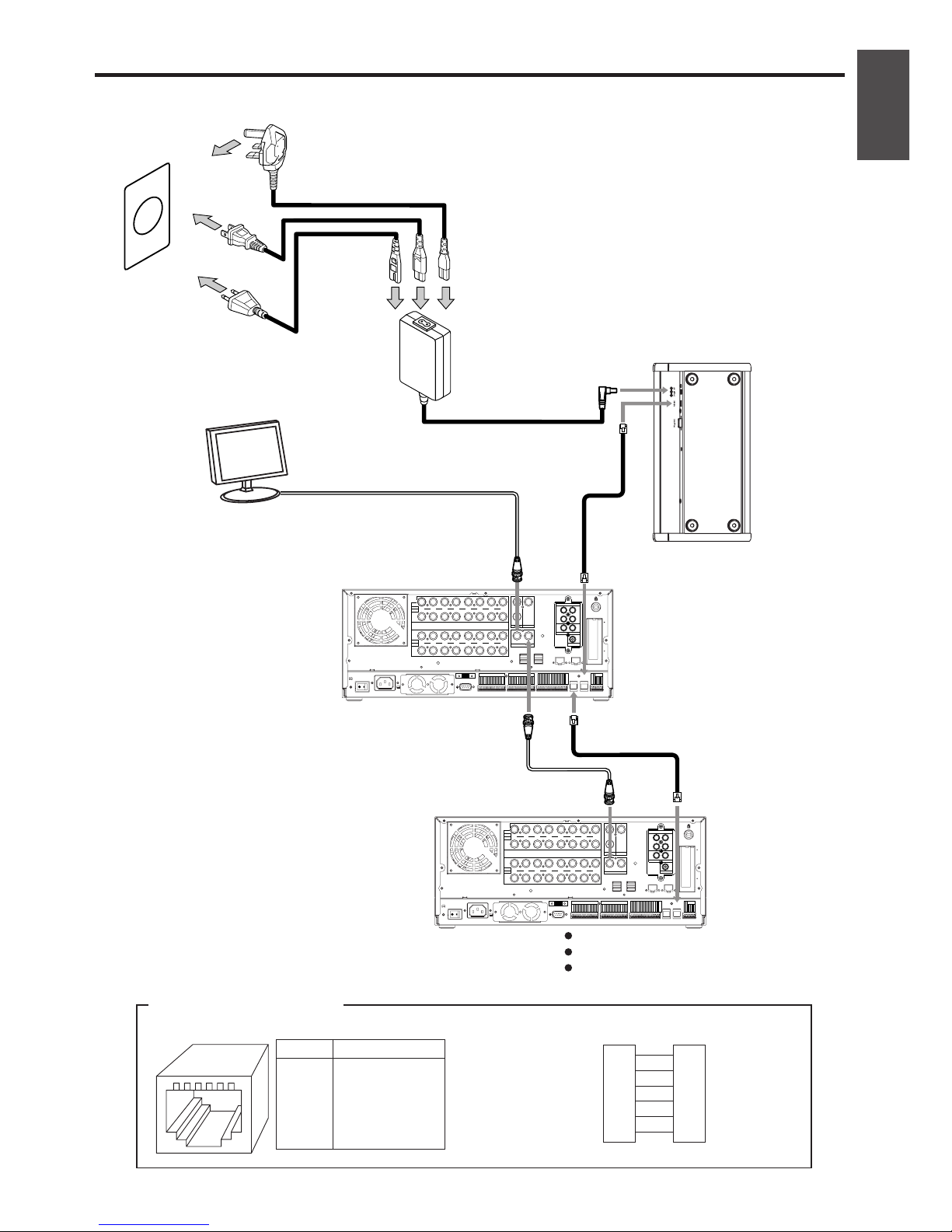
10. Power Sources
This product should be connected only to
its exclusive adapter (DX-EP1E).
11. Object and Liquid Entry
Never push objects of any kind into this
product through openings as they may
touch dangerous voltage points or short-
out parts that could result in a fire or elec-
tric shock. Never spill liquid of any kind
on the product.
12. Servicing
Do not attempt to service this product
yourself as opening or removing covers
may expose you to dangerous voltage or
other hazards. Refer all servicing to quali-
fied service personnel.
13. Damage requiring Service
Disconnect the DC power cord and all
other connections and refer servicing to
qualified service personnel under the fol-
lowing conditions:
(a) When the power-supply cord or plug
is damaged.
(b) If liquid has been spilled, or objects
have fallen into the product.
(c) If the product has been exposed to
rain or water.
PLEASE READ ALL THESE INSTRUCTIONS REGARDING YOUR KEYBOARD AND RE-
TAIN FOR FUTURE REFERENCE. FOLLOW ALL WARNINGS AND INSTRUCTIONS
MARKED ON THE PRODUCT.

ENGLISH
ii
(d) If the product does not operate nor-
mally by following the operating in-
structions. Adjust only those controls
that are covered by the operating in-
structions as an improper adjustment
of other controls may result in dam-
age and will often require extensive
work by a qualified technician to re-
store the product to its normal opera-
tion.
(e) If the product has been dropped or
damaged in any way.
(f) When the product exhibits a distinct
change in performance – this indi-
cates a need for service.
14. Replacement Parts
When replacement parts are required, be
sure the service technician has used re-
placement parts specified by the manu-
facturer or have the same characteristics
as the original part. Unauthorized substi-
tutions may result in fire, electric shock or
other hazards.
15. Safety Check
Upon completion of any service or repairs
to this product, ask the service technician
to perform safety checks to determine that
the product is in proper operating condi-
tions.
16. Heat
The product should be situated away from
heat sources such as radiators, heat reg-
isters, stoves, or other products (includ-
ing amplifiers) that product heat.
WARNING:
TO REDUCE THE RISK OF FIRE OR ELECTRIC SHOCK, DO NOT EXPOSE THIS
PRODUCT TO RAIN OR MOISTURE.
AVERTISSEMENT:
AFIN D’ÉVITER TOUT RISQUE D’INCENDIE OU D’ÉLECTROCUTION, NE PAS
EXPOSER CET APPAREIL À LA PLUIE NI À L’HUMIDITÉ.
INFORMATION
This equipment has been tested and found to comply with the limits for a Class A
digital device, pursuant to Part 15 of the FCC Rules. These limits are designed to
provide reasonable protection against harmful interference in a regidential installa-
tion. This equipment generates, uses, and can radiate radio frequency energy and, if
not installed and used in accordance with the instructions, may cause harmful inter-
ference to radio communications. Operation of this equipment in a residential area is
likely to cause harmful interference in which case the user will be required to correct
the interference at his own expense.
NOTE
THIS CLASS A DIGITAL APPARATUS COMPLIES WITH CANADIAN ICES-003.
CET APPAREIL NUMÉRIQUE DE LA CLASSE A EST CONFORME À LA NORME
NMB-003 DU CANADA.

2
Contents
IMPORTANT SAFEGUARDS ........................................................................................................ i, ii
Caution and care ............................................................................................................................. 3
Major operations and their functions ......................................................................................... 4-6
Top view .................................................................................................................................. 4, 5
Bottom view ................................................................................................................................ 6
Connection ...................................................................................................................................... 7
Initial settings .............................................................................................................................. 8, 9
Setting of the digital recorder ...................................................................................................... 8
Setting of this unit ....................................................................................................................... 8
Mode of this unit ..................................................................................................................... 8, 9
Operating the digital recorder ............................................................................................... 10, 11
Selecting the recorder to be operated ...................................................................................... 10
Switching OUTPUT A and B ..................................................................................................... 10
Multiplexer functions ................................................................................................................. 10
Playback ............................................................................................................................. 10, 11
Controlling PTZ of the camera ..................................................................................................... 12
Selecting the recorder to be operated ...................................................................................... 12
Switching the camera to be controlled ...................................................................................... 12
PTZ control ............................................................................................................................... 12
PTZ help display ....................................................................................................................... 12
Setting the menu of the digital recorder ..................................................................................... 13
Selecting the recorder to be operated ...................................................................................... 13
Setting the menu ...................................................................................................................... 13
Setting the search menu ........................................................................................................... 13
Displaying the help menu ......................................................................................................... 13
Other operations ..................................................................................................................... 14, 15
Selecting the recorder to be operated ...................................................................................... 14
Recording ................................................................................................................................. 14
Lock .......................................................................................................................................... 14
Registering the bookmark ......................................................................................................... 14
ALARM OUT button .................................................................................................................. 14
Checking the connected recorders ........................................................................................... 14
Recorder sequential display .....................................................................................................14
Switching to the warning recorder ............................................................................................ 15
Setting the menu of this unit ..................................................................................................... 15
Camera menu help display ....................................................................................................... 15
Trouble shooting ........................................................................................................................... 16
Specifications ................................................................................................................................ 17

3
ENGLISH
Caution and care
NEVER TOUCH OR INSERT ANY OBJECT INSIDE THE UNIT
Touching the inside of the cabinet or inserting foreign objects of any kind not only creates a safety hazard
but can also cause extensive damage.
MAINTAIN GOOD VENTILATION
For maximum ventilation, leave some space around the unit and place the unit on a hard level surface
only, and ensure it is not covered during use. Heavy objects should never be placed on the unit.
CABINET CARE
Never use petroleum-based cleaners. They may cause deterioration or coat flaking of the unit. Clean
with a soft cloth moistened with soap and water and wipe dry. When using chemical duster, follow the
instructions.
PVC cables or leads should not be left in contact with the cabinet surface for long periods.
INSTALLATION LOCATION
For excellent performance and lasting reliability install in a location that is:-
1. Well ventilated, out of direct sunlight and away from direct heat.
2. A solid vibration-free surface.
3. Free from high humidity, excessive dust and away from magnetic fields.
UNSUITABLE LOCATIONS
Placing the unit in the following places might shorten the product life:
• Extremely cold places, such as refrigerated warehouses and ice houses.
• Places where excessive hydrogen sulfide is likely to be generated, such as hot-springs areas.
• Places or locations with salt air environment.
HEAVY OBJECTS SHOULD NEVER BE PLACED ON THE UNIT (E.G., MONITOR)
This unit complies with the requirements of the EC Directive 89/336/EEC, “EMC Directive,” as amended
by Directive 93/68/EEC. The requirements for the susceptibility according to EN 55024 and the re-
quirements for interference according to EN 55022 (Class B) are observed for the operation on
residential areas, business, light industrial premises and in small scale enterprises, inside as well as
outside of the building. All places of operation are characterised by their connection to the public low
voltage power supply system. This unit is manufactured in accordance with EN 60950.
POWER CORD USED
• The power cords for use in the U.S., the continent of Europe, and U.K. are included with this unit.
Use the appropriate one for your country.
• The power cord for use in the U.S. is used for 120 V only. Never connect to any outlet or power
supply having a different voltage or frequency.
POWER SOURCE USED
• Be sure to use the supplied AC adapter.
HANDLING
• Do not place this unit close to other equipment to prevent adverse interference between them. Do
not place this unit close to strong magnetized objects. They may cause effects on the pictures or
loss of the recorded data.
• Never apply volatile substances such as insecticides and do not put rubber or plastic products on
the unit for a long period. They may cause deterioration of this unit or flaking of the coating.

4
Major operations and their functions
Top view
(When connecting to the digital recorder DX-TL5000 series:)
1810 11
18 19 20 21 2223 24 25 26 27 28 29 30 31 32
23 4 956 7 151312 14 16 17
1 LOCK button
Turns on the lock function of this unit.
2 DIGITAL ZOOM button
Magnifies the picture when pressed during
single screen display or playback. To move
the magnification center point, press camera
number buttons (11, 14, 15, 16).
3 EMERGENCY button
Starts emergency recording.
4 ALARM OUT button
Activates the MODE OUT terminal on the
digital recorder of which “Mode Out Settings”
is set to “LAN.”
5 SEARCH button
Displays the <User Menu> of the digital
recorder with search function items opened.
6 SET UP button
Displays the <User Menu> of the digital
recorder.
7 BOOK MARK button
Displays the selection screen for registering
the bookmark when pressed during still frame
playback of the single screen display.
8 SHIFT button
During PTZ operational mode, uses to select
the camera to be operated for PTZ function.
Uses to switch the operational mode of this
unit to keyboard menu setting mode and
recorder connection check mode.
9 TRIPLEX PLAY BACK button
Switches the digital recorder to triplex
playback mode when pressed during split
screen display.
10 SEQUENCE button
Displays the sequential screen.
11 DVR No. button
Uses to select the recorder to be operated.
12 SEQUENTIAL TIME +, – buttons
Sets the switching time of the recorder
sequential display.
13 INFO. CLEAR button
Clears the warning of the digital recorder
which is displayed on the LCD display on this
unit.

5
ENGLISH
14 HELP button
Displays the help menu of the digital
recorder.
Displays the help menu of the PTZ
operational mode or camera menu mode.
15 OUTPUT A button
Switches the multiplexer operating function of
this unit to output A.
OUTPUT B button
Switches the multiplexer operating function of
this unit to output B.
16 F1 to F6 buttons
Operates the unique functions of each
camera connected.
17 LCD display
Displays the mode of this unit, and status or
recorder number of the digital recorder which
is currently connected, etc.
18 STOP button
Stops playback.
19 PAUSE button
Switches the playback to still frame playback
when pressed during playback.
Displays the still frame playback picture of
the end point of the latest recording when
pressed during stop mode.
20 JOG dial
Forwards or rewinds the picture during
playback (frame-by-frame).
21 SHUTTLE ring
Adjusts the playback speed, and rewinds or
forwards the recorded pictures.
22 REVERSE PLAYBACK button
Starts reverse playback.
Switches the playback interval.
23 PLAYBACK button
Starts playback.
Switches the playback interval.
24 SPLIT SCREEN buttons
Displays the split screen of the selected type.
Uses for setting the menu.
25 1 to 16 buttons
Displays the picture of the selected camera
number.
Selects the digital recorder to be operated.
Uses for setting the menu.
ON/OFF (camera number 9) button
AREA (camera number 13) button
Uses when setting the detection area of the
motion detection function of the digital
recorder.
26 AUTO PAN button
Activates auto pan.
27 ZOOM +, – buttons
Adjusts the camera zoom.
28 FOCUS +, – buttons
Adjusts the focus of the camera.
29 PRESET button
Presets up to 16 watching points.
30 IRIS +, – buttons
Adjusts the iris of the camera.
31 PTZ button
Uses when switching the operational mode of
this unit.
32 Joy stick
Uses to pan or tilt the camera.
Uses to set the menu of this unit.

6
Major operations and their functions (continued)
Bottom view
2143
1 Rotary switch
Used to set the number corresponding to the
recorder connected.
2 RS-232C connector
Used to connect the device equipped with the
RS-232C connector. There is no
corresponding device as of now.
3 RS485 connector
Used to connect the digital recorder.
4 DC IN 9V connector
Used to connect the supplied AC adapter for
the power source.

7
ENGLISH
Connection
100V
AC IN~
MAX 350mA
DC 12V OUT
CLOCK ADJ
CLOCK ADJ OUT
REC
REC STOP
EMERGENCY
RESERVED
MODE OUT 1 +
+
MODE OUT 1 —
MODE OUT 2 +
+
MODE OUT 2 —
MODE OUT 3 +
+
MODE OUT 3 —
MODE OUT 4 +
+
MODE OUT 4 —
CALL OUT +
+
CALL OUT —
GND
GND
GND
GND
1
ALARM IN
2
3
4
5
6
7
8
9
10
11
12
13
14
15
16
RS485 TERM +
+
RS485 TERM —
P T Z
RS422
+
RS422
—
RS232
1
ALARM OUT
2
3
4
5
6
7
8
9
10
11
12
13
14
15
16
RS-232C
RS485RS485
INOUT
MAIN
OFF ON
RESET
OPTION SLOT
LAN-A LAN-B
STORAGE COM
SERIAL BUSSERIAL BUS
1234 5678
9 101112 13141516
OUT
IN
CAMERA
OUT
IN
Y/C
OUTPUT B
CLAMPER
CLAMPER
OUTPUT A
VIDEO VIDEO
VIDEO CASCADE
INOUT
1010010100
AUDIO IN
12
34
OUT
IN
AUDIO CASCADE
AUDIO OUT
Supplied AC adapter
(DX-EP1E)
(For the Continent)
To DC IN 9 V connector
Bottom of
the keyboard
Digital recorder DX-TL5000 series Rear panel
Up to 16 dgital recorders can be connected.
To RS485 connector
To RS485 IN connector
To RS485 OUT connector
(For U. K.)
(For U. S.)
To household
power source
To VIDEO CASCADE OUT connector
To VIDEO CASCADE IN connector
To VIDEO CASCADE OUT connector
1
2
3
4
5
6
1
2
3
4
5
6
1
2
3
4
5
6
GND
GND
RS485+
RS485-
RESERVE (open)
RESERVE (open)
GND
GND
RS485+
RS485-
RESERVE (open)
RESERVE (open)
GND
GND
RS485+
RS485-
RESERVE (open)
RESERVE (open)
123456
RS485 connector Cable connection
Pin No. Signal name
Information of RS485 connection
Monitor
(When connecting to the digital recorder DX-TL5000 series:)

8
Initial settings
(When connecting to the digital recorder DX-TL5000 series:)
Setting of the digital recorder
Setting of the cascade connection
Set the cascade connection mode and the recorder address in the <RS-485 Cascade Setting>
(System Menu COM/LAN) of the digital recorder. Refer to the manual of the digital recorder for
the detailed operation.
Setting of this unit
Set the rotaly switch on the rear of this unit to 1.
Mode of this unit
This unit is equipped with following 6 operational modes.
Recorder operational mode
This is the mode to operate the digital recorder connected. You can operate up to 16 digital
recorders when the cascade connection is made.
Keyboard menu setting mode
This is the mode to set the menu of this unit.
Recorder sequential display mode
This is the mode to sequentially switch the digital recorder of which picture is displayed at the
interval of specified switching time.
Recorder connection check mode
This is the mode to check the digital recorders connected.
PTZ operational mode
This is the mode to operate the function of the camera which supports PTZ function and
connected to the digital recorder. You can operate the camera which is connected up to 16 digital
recorders when the cascade connection is made. (This mode is invalid depending on the camera
connected.)
Camera menu mode
This is the mode to operate the menu of the camera connected. (This mode is invalid depending
on the camera connected.)

9
ENGLISH
SET UP button
PTZ
button
Camera
menu mode
PTZ
operational
mode
PTZ
button
PTZ
button
Recorder
operational
mode
Recorder
connection
check mode
DVR No.
button +
SEQUENCE button
DVR No.
button
SET UP button
SHIFT button +
SET UP button
any button
SHIFT button +
DVR No.
button
Recorder
sequential
display mode
Keyboad
menu setting
mode
Mode to operate the digital recorder.
Mode to operate the camera.
Mode to set the menu of this unit.
Display of LCD:
KEYBOARD MENU
Display of LCD:
SEQUENCE
Display of LCD:
DVR MODE Display of LCD:
PTZ MODE
Display of LCD:
CAM MENU
Display of LCD:
DVR CONNECTION CHECK
•To switch the mode of this unit, press the following button. You can confirm the current mode by
checking the LCD display of this unit.

10
Operating the digital recorder
(When connecting to the digital recorder DX-TL5000 series:)
Before operating, set the operational mode of this unit to the mode shown on the right of
each function. (Refer to page 9 for setting the operational mode.)
Selecting the recorder to be operated
Recorder operational mode
1 Press the DVR No. button.
2 Press the number button (1 to 16) corresponding to the ID number of the recorder to be
operated.
Switching OUTPUT A and B
Recorder operational mode
When the OUTPUT A or OUTPUT B button is pressed, the multiplexer operating function of this
unit is switched between OUTPUT A and B.
Multiplexer functions
Recorder operational mode
Single screen display
When the number button (1 to 16) is pressed, the picture of the camera connected to the digital
recorder is displayed in the single screen. The number of the button corresponds to that of the
CAMERA IN terminal on the rear panel of the digital recorder.
Split screen display
When the SPLIT SCREEN buttons are pressed, the split screen of the selected type is displayed.
The different pattern of the selected split screen is displayed each time you press the button.
Sequential display
When the SEQUENCE button is pressed, the sequential screen is displayed in the screen pattern
being displayed.
Playback
Recorder operational mode
Playback/Reverse playback
•When the PLAYBACK button is pressed, the recorded contents of the digital recorder is played
back.
•When the REVERSE PLAYBACK button is pressed, the playback in the reverse direction is
started.
•When the PLAYBACK button is pressed for the first time after turning on the power of the
digital recorder, the playback starts from the oldest recording point. Otherwise, the playback
starts from the stopped position of the previous playback.
•When the REVERSE PLAYBACK button is pressed for the first time after turning on the power
of the digital recorder, the reverse playback starts from the latest recording point.
Still frame playback
•When the PAUSE button is pressed during playback or reverse playback, the playback
switches to still frame playback.
•When the button is pressed again, the playback or reverse playback is resumed.
•When the PAUSE button is pressed during stop mode, the still frame playback picture of the
latest recording point is displayed.
Changing the playback speed
•When the SHUTTLE ring is turned during playback, reverse playback, or still frame playback,
the playback speed is changed. The speed changes on a step of 1 to 4 depending on the
angle of the SHUTTLE ring turned.

11
ENGLISH
High speed fast forward/High speed rewind playback
•When the SHUTTLE ring is turned to the right for more than 1 second during stop mode, the
high speed fast forward playback is carried out.
•When the SHUTTLE ring is turned to the left for more than 1 second during stop mode, the
high speed rewind playback is carried out.
Frame-by-frame playback
•When the JOG dial is turned to the right during still frame playback, the frame-by-frame
playback in the forward direction is carried out.
•When the JOG dial is turned to the left during still frame playback, the frame-by-frame
playback in the reverse direction is carried out.
•When keeping turning the JOG dial, the continuous frame-by-frame playback is carried out.
•When the turning of the JOG dial is stopped, the still frame playback is resumed.
Stopping the playback
•When the STOP button is pressed during playback, reverse playback, or still frame playback,
the playback is stopped.
Changing the playback interval
•When the PLAYBACK button is pressed during playback or reverse playback, the picture
recorded at the long recording interval is played back fast. The playback is made at a speed of
100 pps (for DX-TL5000E)/120 pps (for DX-TL5000U) in total. When the REVERSE
PLAYBACK button is pressed, the playback speed becomes slower each time you press the
button (up to 0.125 pps).
•When the REVERSE PLAYBACK button is pressed during playback or reverse playback, the
picture recorded at the short recording interval is played back slowly. The playback is made at
a speed of 0.125 pps per camera. When the PLAYBACK button is pressed, the playback
speed becomes faster each time you press the button (up to 100 pps (for DX-TL5000E)/120
pps (for DX-TL5000U)).
Triplex playback
This function is used to insert the playback picture of the desired camera number during split
screen display.
•When the TRIPLEX PLAY BACK button is pressed during split screen display, the digital
recorder is switched to the triplex playback mode.
•When the desired camera number button (1 to 16) is pressed within 3 seconds after switching
to the triplex playback mode, the playback picture of the selected camera number is displayed.
Only the playback picture of the camera number which is being displayed in the split screen
can be inserted.
•When the STOP button is pressed, the playback is stopped.

12
Controlling PTZ of the camera
Before operating, set the operational mode of this unit to the mode shown on the right of
each function. (Refer to page 9 for setting the operational mode.)
Selecting the recorder to be operated
Recorder operational mode
1 Press the DVR No. button.
2 Press the number button (1 to 16) corresponding to the ID number of the recorder to be
operated. The PTZ function of the camera connected to that recorder can be controlled.
Switching the camera to be controlled
PTZ operational mode
•During split screen display, switch the mode of this unit to PTZ operational mode. Press the
SHIFT button and then press the camera number button (1 to 16) to be controlled. Only the
cameras of which picture is being displayed in the split screen can be switched.
PTZ control
PTZ operational mode
Tilt
Tilt the joy stick to the upward direction to adjust the camera angle upward.
Tilt the joy stick to the downward direction to adjust the camera angle downward.
Pan
Tilt the joy stick rightward or leftward to pan the camera.
Camera zoom
Press the ZOOM + button (tele) or ZOOM –button (wide) to adjust the camera zoom.
Focus
Press the FOCUS + button (far) or FOCUS –button (near) to adjust the focus of the camera.
Iris
Press the IRIS + button (close) or IRIS –button (open) to adjust the iris of the camera.
Preset
Press the PRESET button and then press the number button (1 to 16) within 3 seconds to preset
the watching points. Up to 16 points can be set.
Auto pan
Press the AUTO PAN button to carry out the auto pan.
PTZ help display
PTZ operational mode
•When the HELP button is pressed during PTZ operational mode, the assignment of buttons for
operating the unique function of the selected camera is shown on the LCD display.
•Each time the HELP button is pressed, the next line is appeared.

13
ENGLISH
Setting the menu of the digital recorder
Before operating, set the operational mode of this unit to the mode shown on the right of
each function. (Refer to page 9 for setting the operational mode.)
Selecting the recorder to be operated
Recorder operational mode
1 Press the DVR No. button.
2 Press the number button (1 to 16) corresponding to the ID number of the recorder to be
operated.
Setting the menu
Recorder operational mode
•Press the SET UP button to display the <User Menu> of the digital recorder.
•The following buttons are used to set the menu.
–SPLIT SCREEN buttons : Used to operate the buttons on the menu screen which are
shown with the alphabets A to E.
–1 to 16 buttons : Used to operate the buttons on the menu screen which are
shown with the figures 1 to 16.
Setting the search menu
Recorder operational mode
•Press the SEARCH button to display the <User Menu> of the digital recorder with the search
function items opened.
•The following buttons are used to set the menu.
–SPLIT SCREEN buttons : Used to operate the buttons on the menu screen which are
shown with the alphabets A to E.
–1 to 16 buttons : Used to operate the buttons on the menu screen which are
shown with the figures 1 to 16.
Displaying the help menu
Recorder operational mode
Press the HELP button to display the help menu of the digital recorder which shows the caution on
use, operating method, or explanation on functions. The help menu can be displayed even while
the menu screen is displayed.

14
Other operations
Before operating, set the operational mode of this unit to the mode shown on the right of
each function. (Refer to page 9 for setting the operational mode.)
Selecting the recorder to be operated
Recorder operational mode
1 Press the DVR No. button.
2 Press the number button (1 to 16) corresponding to the ID number of the recorder to be
operated.
Recording
Recorder operational mode
When the EMERGENCY button is pressed, the emergency recording starts.
Lock
Recorder operational mode
•When the LOCK button is pressed, the lock function of this unit is turned on.
Registering the bookmark
Recorder operational mode
When the BOOK MARK button is pressed during the still frame playback of the single screen, the
selection screen is displayed and the bookmark can be registered.
•The following buttons are used to set the menu.
–SPLIT SCREEN buttons : Used to operate the buttons on the menu screen which are
shown with the alphabets A to E.
–1 to 16 buttons : Used to operate the buttons on the menu screen which are
shown with the figures 1 to 16.
ALARM OUT button
Recorder operational mode
When the ALARM OUT button is pressed, the MODE OUT terminal on the digital recorder of which
“Mode Out Settings”is set to “LAN”is activated. By using this button, you can remotely control the
device connected to the MODE OUT terminal of the digital recorder.
Checking the connected recorders
Recorder connection check mode
•When this unit is switched to recorder connection check mode, the number buttons (1 to 16)
corresponding to the connected recorder numbers are illuminated, and you can check the
digital recorders which are currently connected.
Recorder sequential display
Recorder sequential display mode
•When this unit is switched to recorder sequential display mode, the recorder of which picture is
displayed switches sequentially at the interval of specified switching time (default setting is 5
seconds).
•When the SEQUENTIAL TIME +, –button is pressed, the switching time is changed between
the range of 2 to 60 seconds.
•When the DVR No. button is pressed, the mode of this unit is resumed to the recorder
operational mode.

15
ENGLISH
Switching to the warning recorder
Recorder operational mode
Recorder connection check mode
Recorder sequential display mode
PTZ operational mode
•When this unit receives the warning of the digital recorder, this unit connects to that recorder
automatically.
•When the INFO. CLEAR button is pressed, the warning is cleared.
•Set “WARNING ON/OFF”menu to “ON”to activate this function.
Setting the menu of this unit
Keyboad menu setting mode
•Tilt the joy stick upward or downward to select the menu item.
•Tilt the joy stick leftward or rightward to select the setting item.
•When the SET UP button is pressed, the setting is determined and the recorder operational
mode is resumed.
WARNING ON/OFF
KEY SOUND ON/OFF
ON
OFF
ON
OFF
Menu item Setting item Function
Automatically connects to the warning recorder.
Does not automatically connect to the warning recorder
although the warning is displayed on the LCD display.
Turns on the key sound of this unit.
Turns off the key sound of this unit.
Camera menu help display
Camera menu mode
•When the HELP button is pressed during camera menu mode, the assignment of buttons for
operating the menu of the selected camera is shown on the LCD display.
•Each time the HELP button is pressed, the next line is appeared.

16
Trouble shooting
If problems with the unit persist even after you have followed the suggestions below, disconnect the
power cord and contact the retailer from whom you purchased the unit.
Description of problem
The recorder cannot be controlled.
The power cannot be turned on.
The recorder cannot be selected.
The camera cannot be controlled.
Consult the following
•Is the connection made correctly?
•Is the power of the recorder turned on?
•Is the cascade recorder address set?
•Is the desired recorder selected?
•Is the recorder in cascade mode?
•Is the AC adapter connected correctly?
•Is the connection made correctly?
•Is the power of the recorder turned on?
•Is the cascade recorder address set?
•Is the recorder in cascade mode?
•Is the connection made correctly?
Check the RS485 and RS-232C connections between
the digital recorder and the camera.
•Is the power of the recorder turned on?
•Is the <PTZ Setting> menu of the recorder set
correctly?

17
ENGLISH
Specifications
AC Adapter Class AC adapter
(DX-EP1E) Rated power supply 100-240 V AC; 50/60 Hz
Maximum current 1.0 A
Rated output DC 9 V, 1.67 A
Dimensions 56 (W) X 25.5 (D) X 85 (H) mm (excluding the cord)
Weight 0.3 kg (including the AC adapter and cord)
DX-KB5UE Rated power supply DC 9 V
Rated input 0.5 A
Operation temperature 41 ºF to 104 ºF (5 ºC to 40 ºC)
Relative humidity Max. 80 %
Altitude Max. 2000 m
Dimensions 365 (W) X 201 (D) X 94 (H) mm
Weight 2.0 kg
Control terminal RS-485 port RS-485 Output RJ-11
Serial port RS-232C D-SUB 9 pin
Accessories 3 AC power cords (for U. K./for the Continent/for U. S.)
1 AC adapter (DX-EP1E)

SLD Security & Communications
The Old Forge, Ockham Lane, Ockham, Surrey GU23 6PH England
Phone +44.1483225633 · Fax +44.1483225634
Other manuals for DX-KB5UE
1
Table of contents
Other Mitsubishi Electric Keyboard manuals
Popular Keyboard manuals by other brands

American Dynamics
American Dynamics Matrix Keyboard Operator's manual

Leicke
Leicke Sharon SI54223 manual

Genius KYE Systems
Genius KYE Systems SlimStar 100 Service guide

midiplus
midiplus Tiny Series user manual

Mountain
Mountain BASE CAMP quick start guide

Belkin
Belkin F8U1500 - Wireless PDA Keyboard user guide