ù'
f, ..--'--
F!t
l, !
i;i
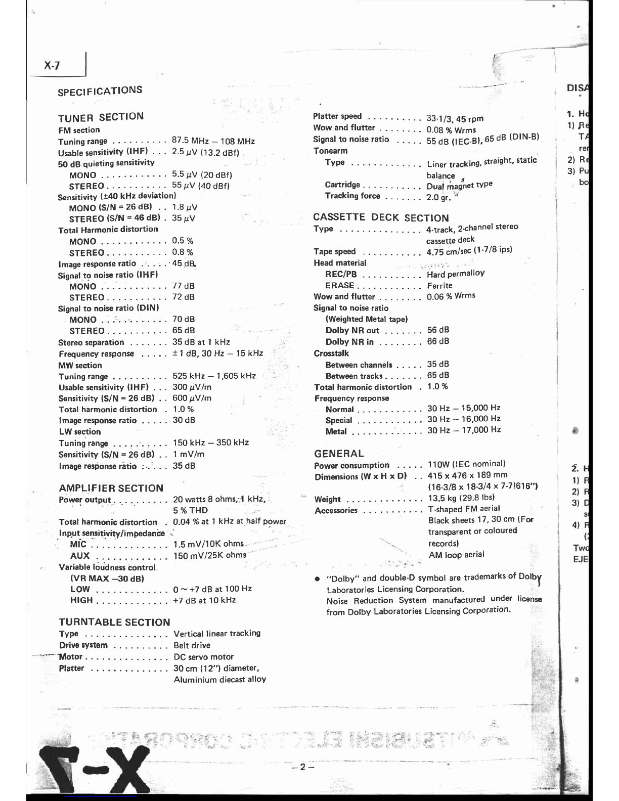
Tracking
force . 2.0gr.
v î
I
CASSETTE
DECK
SECTION
Type . ...4-track,2+hannelstereo i
æssette
deck i
Tape
speed ïii",^ttn (1-718
iPs) I
,l
Head
material ..
i..:r
{-{ I
REC/PB Hard
PermalloV i
i
MONO . . 77dB ERASE . Ferrite
STEBEO . 72dB Wow
andflutter . . 0.06
%
Wrms
Signal
to noise
ratio (DlNl Signal
to noiseratio
MONO
.:.''..'....::. 70dB (WeightedMetaltapel
STEREO...:. .65d8 DolbyNRout.......56dB
Stereoseparation ..3sdBatlkHz ''" DolbyNRin...."" 66dB
Frequency
responss t 1dB,30 Hz- 15kHz ' Crosstalk
MWsection i Between
channell " " ' 35 d8
Tuningrange. ....525kH2-l,605kHz I Batrreentracks "65dB
Usable
sensitivity
(lHFl . . . 300pVlm Totalharmonic
distortion . 1.0
%
sensitivity ls/N = 26 dBl . . 600pVlm Frequency
resPonso
Totalharmonic
distortion 1.0
%
lmageresponseratio.....3OdB Special .30H2-16,000H2
LWsestion ' ' Metal ' 30 Hz - 17'000 Hz
Tuninglange. ;... 150kHz-350kHz
Sensitivity
(S/N
= 26dB) . . 1mV/m GENERAL
tmaç resionse
râtio :..'. . . 35dB Power
consumption 110W
(lEC
nominal) 2-
Dimensions(WxHxD)
.- 415
x476xt8ntT-.^.^,,.' l)
AMPLIF|
ER
sEcrloN 116'g/8x18-314x7-71616"1
::
,^^ ô ll-l Zt
Poweroutpùt 2owattsSohmsJ
kHz,, -' Weight
..... .... 13.5kS(29'8lbs) , 1l
- - -, ; - -L --^i Ert ^^vial rt
Totalharmonic
distortion . O.O4
%
at 1kHzathalfpower Black
sheets
17'30cm (For
.lnp.ut-sensitivity/impedanb - transparent
or coloured
. rvri'c
..... .... 1.5mV/10Kohms
' '..- records)
AUX . . . 150
mV/25K
ohms " AM loop
aerial
, Variablelôudness
êontrol : 'r : ' '
(VR MAX -30 dB) o ,,Dolby" anddoubte-D
rymbol are
trademarks
of Dolbl
LOW . . . O
-+7 dB at 100
Hz Laboratories
Licensing
Corporation. '
HIGH . . . +7 d}at l0 kHz Noise Reduction System manufactured
under licensc
from Dolby Laboratories
Licensing
Corporation'
TURNTABLESECTION
Type . .... Vertical
lineartracking
Drivesystem
' -*-.- Îùlotor DCservo
motor i. ,r
,.,.
Platter . . . . 30 cm 112"1
diameter, ài '. 1'
Aluminium diecast
alloY li,;..;:i
, .'-':,i