Daktronics Sportsound SSR-200 User manual

Sportsound SSR-200 Quick Start Guide 1 of 5
DD2298940 Rev 1
12 March 2014
201 Daktronics Drive PO Box 5128, Brookings, SD 57006-5128
Tel: 1-800-DAKTRONICS (1-800-325-8766) Fax: 605-697-4746
Web: www.daktronics.com/support
This guide will assist with starting up and operating a Sportsound®SSR-200
audio rack. For detailed operation, conguration, and troubleshooting,
refer to the Sportsound Rack SSR-200 Operation Manual (DD2298630).
Startup
Before Beginning: Place the rack on a at, sturdy surface. Remove the
cover pieces by twisting the knobs away from each other, and set them
aside. Accessories are located in a separate case.
1. Connect one end of the XLR gooseneck to the wired microphone
and the other end into the jack on top of the announcer’s interface.
Optional headset microphone may be plugged here instead.
2. Connect the 15' (4.6 m) XLR cable from MIC 1 & AUX 1 on the
announcer’s interface to MIC 1 & AUX 1 on the rear of the rack.
3. Connect one end of the 5' (1.5 m) XLR cable to the LTIBLOX Laptop
Interface and the other end to MIC2. The 3.5 mm plug may be
connected to the headphone jack of a laptop or MP3 player.
4. Connect the 25' (7.6 m) XLR cable between the AUDIO OUT jack on
the rear of the rack and the SYSTEM AUDIO jack on the bottom of
the ber box. If there is no ber box, the cable will typically connect
to a wall plate junction box instead.
5. Locate the 3-prong power cord and plug into a standard outlet.
Ensure the announcer’s interface and ber box (if included) also
have power.
6. Turn on the power strip.
7. Switch the SOUND SYSTEM to ON.
Power Down
Follow the above steps in reverse order to power down the system.
Place all accessories in the storage case.
Ensure all antennas are angled outward at ~45◦. Alternately, coaxial
cable from the high gain antenna kit may be connected into ANT1 and
ANT4. The antennas should be located within 50' (15.2 m) of the rack,
using desktop stands or mounted to the ceiling.
Fiber Box OR Wall Plate
Announcer’s
Interface
12
Laptop
Interface
Rear View
Hearing
Assist System
(optional)
Personal Monitor
System (optional)
CD Player
Wireless Mic System
Audio Mixer
4
5
3
7
6

Sportsound SSR-200 Quick Start Guide 2 of 5
DD2298940 Rev 1
12 March 2014
201 Daktronics Drive PO Box 5128, Brookings, SD 57006-5128
Tel: 1-800-DAKTRONICS (1-800-325-8766) Fax: 605-697-4746
Web: www.daktronics.com/support
• For each input channel (source) in use, verify:
- INSERT jack has nothing plugged into it
- GAIN knob is set to an appropriate level
- PAN knob is set to the center position
- MUTE button is not depressed
• Depress the PFL button to listen to each
input channel without interrupting the
main mix.
With an input source playing or while
speaking into the microphone, adjust the
gain knob and channel fader until the
output meter shows 0 dB. Release the PFL
button, and repeat this step for all other
channels in use.
Note: The PEAK LED indicates that the
signal is close to distorting (clipping).
• Slowly bring up the channel and master
volume faders until the output meter
displays 0 dB or adequate volume is
achieved. Red LEDs indicate clipping.
Also ensure the 2 TRACK MONITOR
button is not depressed.
• Ensure the mixer is always outputting
PHANTOM POWER (required for the
announcer’s interface muting circuit).
Audio Mixer Operation
REMEMBER: Bad input = bad output. No adjustment
on the mixer can make a poor source sound better.
For best results, be sure to use high-quality audio les
from your MP3 player or laptop, and set the device to
near full volume.
• Ensure all source equipment is turned on and operational
(refer to the appropriate pages of this guide).

Sportsound SSR-200 Quick Start Guide 3 of 5
DD2298940 Rev 1
12 March 2014
201 Daktronics Drive PO Box 5128, Brookings, SD 57006-5128
Tel: 1-800-DAKTRONICS (1-800-325-8766) Fax: 605-697-4746
Web: www.daktronics.com/support
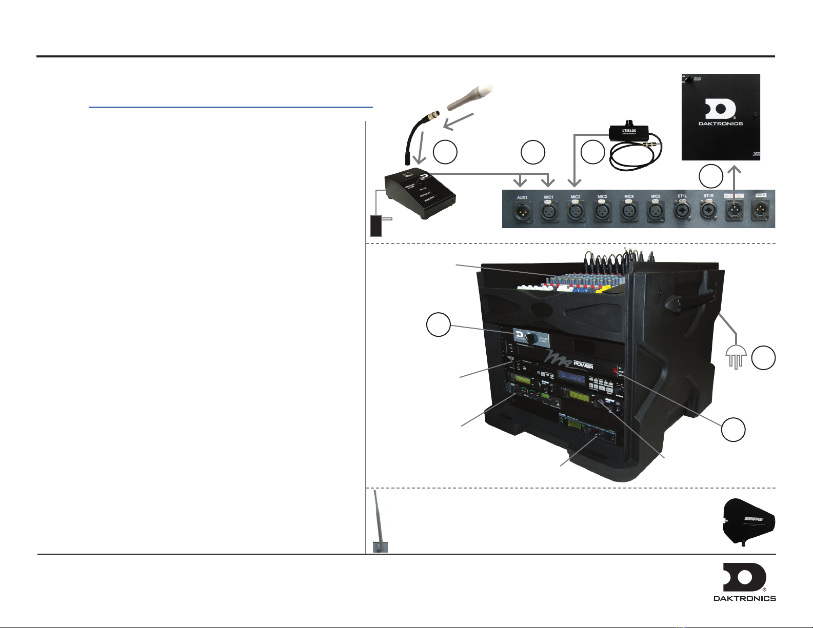
Wireless Receiver System Operation
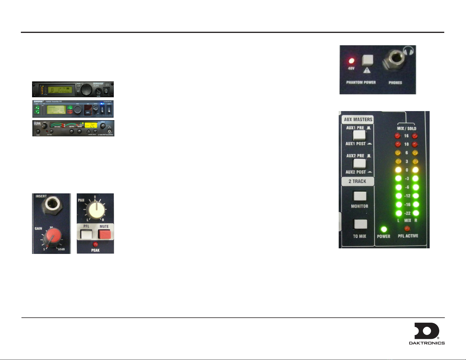
1. Ensure all transmitters are powered off. Flip the power on/off
switch to turn on one receiver if it is not already on.
The unit can display the following information:
a) Group Number
b) Channel Number
c) Transmitter Battery Life
2. Hold the SET button and then press MODE once. The word SCAN
will appear on the display. To begin scanning, simply rotate the
control knob. When all groups have been scanned, the group with
the most open channels will appear. Press SET to accept the
recommended GROUP and assign the clearest CHANNEL.
3. Turn on the second receiver unit. Press MODE twice and use the
control knob to select the same GROUP as the rst receiver.
Press SET and select a different CHANNEL than the rst receiver.
The next highest number should work, but it may be necessary
to select another. Press SET again to save the settings.
Note: Perform a scan on all of the wireless units just minutes before
the game! If a scan is performed too far ahead of time, frequencies set
up by the media later on may interfere with previously congured
wireless microphone settings.
a b c
e fd
Wireless Microphone & Bodypack Operation
1. Open the battery cover. Insert new or fully-charged 9V batteries prior to each
use, and always have spares on hand.
2. Power on the device. Note that with the handheld mic, you must remove the
protective sleeve to access the power and control buttons.
3. Hold MODE until only the GROUP number is visible. Use SET to select
the same group number as the rst receiver unit. Press MODE to continue.
Use SET to select the same CHANNEL number as the rst receiver unit and
then press MODE to save the settings.
4. Repeat steps 1-3 with the second transmitting device, using the GROUP and
CHANNEL settings of the second receiver unit.
Note: Plug the mic switch into the jack on top of the bodypack unit and plug
headphones/lapel mic into the mic switch.
Verify Reception: With a transmitter and the receiver both turned on and
having matching GROUP and CHANNEL numbers, the RF meter on the receiver
should be indicating signal. Speak into the microphone and the TX AUDIO meter
should indicate signal presence.
Power
ON/OFF
Power
ON/OFF
Power
ON/OFF
Control
Knob
Control
Buttons
d) RF Signal Strength
e) Transmitted Audio Signal Strength
f) Frequency

Sportsound SSR-200 Quick Start Guide 4 of 5
DD2298940 Rev 1
12 March 2014
201 Daktronics Drive PO Box 5128, Brookings, SD 57006-5128
Tel: 1-800-DAKTRONICS (1-800-325-8766) Fax: 605-697-4746
Web: www.daktronics.com/support
Optional Personal Monitor System Operation
1. Flip the transmitter POWER switch to ON if it is not already on; ensure the RF
switch to the left of it is OFF at this time.
2. Power on the handheld receiver using the volume knob.
3. Attach the antenna and earphones to the top of the handheld receiver.
4. Flip open the battery cover to expose the control buttons. Press SCAN and the
display will show “SYNC NOW”.
Note: Insert new or fully-charged batteries prior to each use, and always
have spares on hand.
4. Hold the bodypack up to the transmitter with the sync IR windows facing
each other, and press the SYNC button on the transmitter. The display will
show “SYNC SUCCESS” when nished.
5. Flip the transmitter RF switch to ON. The blue LED on the receiver should
illuminate to indicate that it is detecting the transmitter.
1
3
2
4
5 6

Sportsound SSR-200 Quick Start Guide 5 of 5
DD2298940 Rev 1
12 March 2014
201 Daktronics Drive PO Box 5128, Brookings, SD 57006-5128
Tel: 1-800-DAKTRONICS (1-800-325-8766) Fax: 605-697-4746
Web: www.daktronics.com/support
1. Press POWER to turn on the transmitter if it is not already on.
2. Use the CHANNEL SELECT buttons to select a channel.
3. Plug the earphones into the jack on top of the handheld receiver.
4. Rotate the volume dial counterclockwise to power on the handheld receiver.
5. Flip open the battery cover to expose the control buttons. Use the CHANNEL
SELECT buttons to select the same channel that was set on the transmitter,
or press SEEK to locate the active channel.
Note: Insert new or fully-charged batteries prior to each use, and always
have spares on hand.
6. Repeat steps 3-5 for any additional receivers.
34
5
12
Optional Hearing Assist System Operation
The universal antenna kit may be located up to 10' (3 m) away from the
rack, mounted to the ceiling or a wall. Ensure there is enough room to
fully extend the antennas and that the coaxial cable is plugged into the
ANT3 jack on the rear of the rack.
Other manuals for Sportsound SSR-200
3
Table of contents
Other Daktronics Stereo System manuals

Daktronics
Daktronics Sportsound SSR-300 User manual

Daktronics
Daktronics SPORTSOUND 2000HD Instruction Manual

Daktronics
Daktronics Sportsound SS-200 User manual

Daktronics
Daktronics SPORTSOUND 1500HD GEN II User manual

Daktronics
Daktronics SPORTSOUND 2000HD User manual

Daktronics
Daktronics SPORTSOUND 500HD User manual

Daktronics
Daktronics SPORTSOUND SSN-250 User manual

Daktronics
Daktronics Sportsound SSR-200 User manual