Mitsubishi Electric HS-U449 User manual

SPECIFICATIONS
Tape Format
Power Source
Power Consumption
Video Signal System
Video Recording System
Luminance
Color Signal
Hi-Fi Audio
Recording System
Linear Audio Track
Tape Speed
Record/Playback Time
Record/Playback System
Video
Hi-Fi Audio
Monaural Audio Control
Erase
Video Input
Audio Input
Video Output
Audio Output
Tuner VHF
UHF
CATV
Operating Temperature
Relative Humidity
RF Channel Output
Weight
Dimensions
Timer Program Capacity
Deck
: VHS 1/2” high-density video
cassette tape
: 120 V AC ; 60 Hz
: Approx. 20 W (STBY 3 W)
: EIA standard ; NTSC color
: VHS standard
: Frequency modulation recording
: Low frequency conversion
sub-carrier phase shift recording
: VHS standard
Azimuth helical scanning system
: 1 track
: 1-5/16 i.p.s (standard play)
7/16 i.p.s (extended play)
:
120 min. with T-120 video cassette
(SP mode)
360 min. with T-120 video cassette
(EP mode)
: 4 heads
: 2 heads
: 1 head
: 1 head
:
0.5 - 2.0 V(p-p), 75 Ωunbalanced
RCA Pin Jack
:
346 mV(rms), 47 kΩunbalanced
RCA Pin Jack
: 1.0 V(p-p), 75 Ωunbalanced
RCA Pin Jack
: 346 mV(rms), 1 kΩunbalanced
RCA Pin Jack
: 54 - 88 MHz, 174 - 216 MHz
: 470 - 806 MHz
: 54 - 88 MHz, 90 - 804 MHz
: 41 - 104°F
: 30 - 80%
: Channel 3 or 4 switchable
: Approx. 8.0 lbs. (3.6 kg)
: 16.7”(W) ×3.7”(H) ×11.9”(D)
425 (W) ×93 (H) ×302 (D) mm
: 1 month programmable
/ 8 programs
:αDeck
• Weight and dimensions shown are approximate.
• Design and specifications are subject to change without notice.
Only cassettes marked VHS can be used with this video cassette recorder.
2003
VIDEO CASSETTE RECORDER
MITSUBISHI DIGITAL ELECTRONICS AMERICA, INC.
9351 Jeronimo Ave. Irvine, California 92618 U.S.A.
Copyright C2003 Mitsubishi Digital Electronics America, Inc. All Rights Reserved.
MODEL
HS-U449

-
2
-
CONTENTS
- FILE "COVERPGE" -
SPECIFICATIONS ...........................................................1
CONTENTS......................................................................2
GLOSSARY OF ABBREVIATIONS.................................4
- FILE "DISASSY" -
SAFETY PRECAUTIONS ................................................1
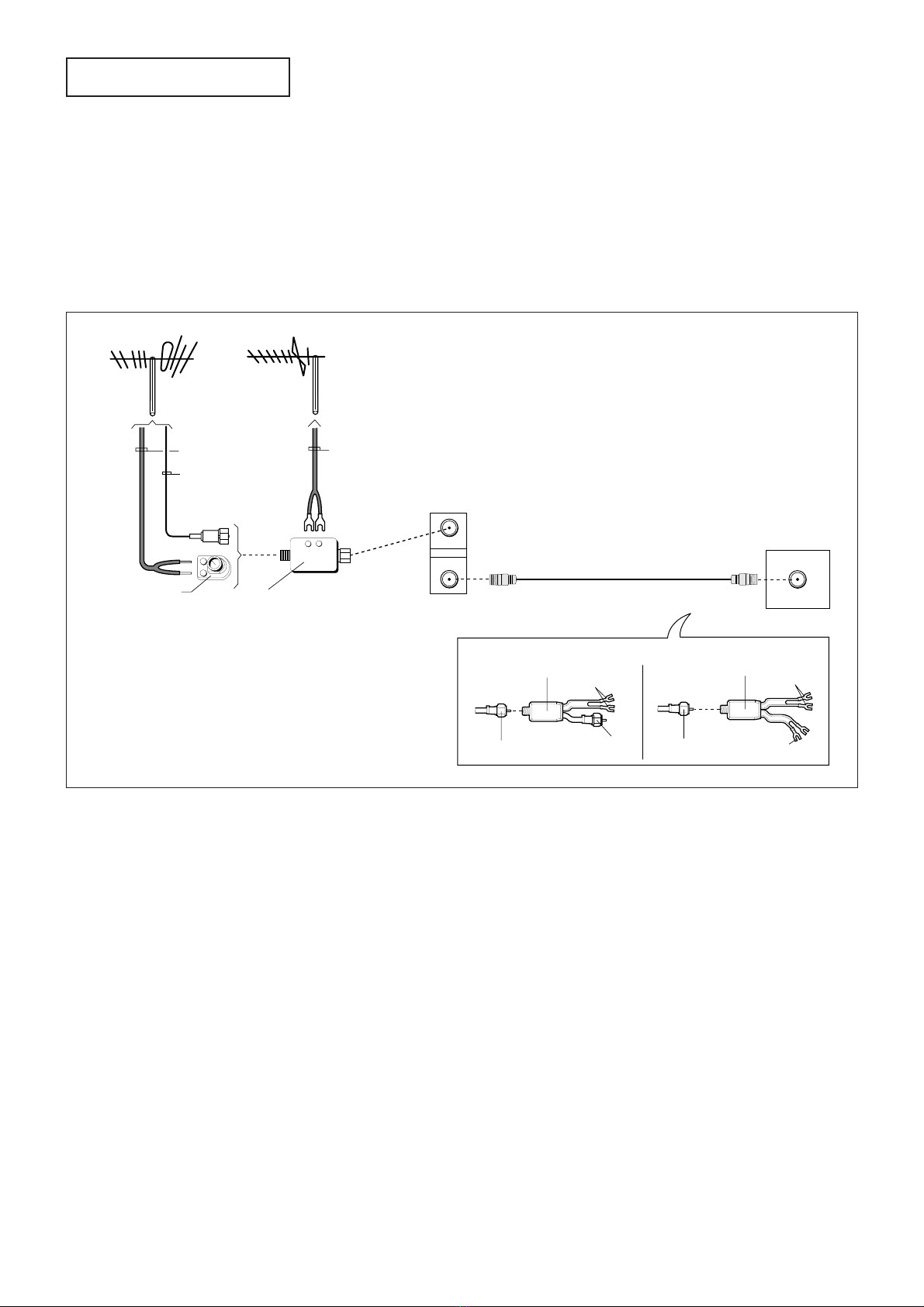
CONNECTION .................................................................3
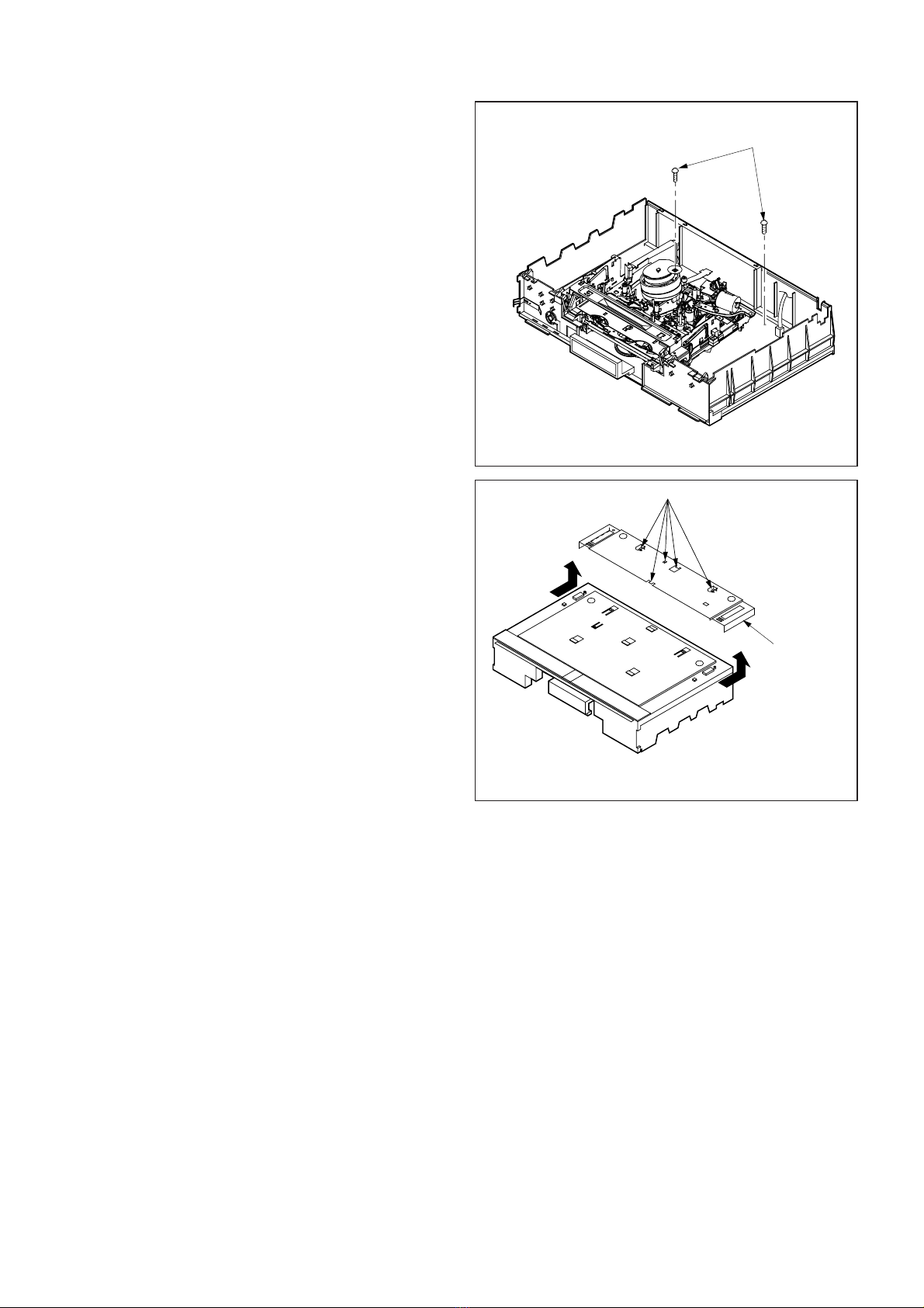
DISASSEMBLY................................................................4
HOW TO EXECUTE CIRCUIT BOARD SERVICE...........7
CHIP PARTS REPLACEMENT........................................9
- FILE "ELCTADJ" -
HOW TO INITIALIZE THE E2PROM................................1
WHEN REPLACING IC5A0 .............................................1
ELECTRICAL ADJUSTMENTS.......................................1
Servo circuit..................................................................2
- FILE "MECHAADJ" -
MECHANICAL ADJUSTMENT
AND REPLACEMENT...............................1
1. DECK Cleaning...................................................1
1-1 VIDEO HEAD .................................................1
1-2 Tape Running System ....................................1
1-3 REEL DISK Drive System ..............................1
2. Replacement of Major Parts ..............................2
2-1 CLEANING ARM ...........................................2
2-2 STAY PLATE ..................................................2
2-3 BOTTOM ASSY.............................................3
2-4 INSERT GUIDE (TU).....................................4
2-5 INSERT GUIDE (SP).....................................4
2-6 REC HOLDER, REC LEVER,
REC SPRING ................................................5
2-7 F/L ARM ASSY, F/L BEARING......................5
2-8 A/C HEAD UNIT ............................................6
2-9 F/E HEAD UNIT.............................................6
2-10 SENSOR COVER (TU)..................................7
2-11 SENSOR COVER (SP)..................................7
2-12 REV UNIT (TU),
REV UNIT (SP)..............................................8
2-13 MODE POSITION UNIT ................................8
2-14 REEL BELT, PULLEY BUSH,
THRUST WASHER,
BELT PULLEY, SHIFT SLIDER,
PULLEY GEAR ASSY, SLIP GEAR,
SLIP SPRING, SLIP WASHER,
THRUST WASHER, SLIP ADJUSTER,
IDLER 2 UNIT................................................9
2-15. CAPSTAN BRAKE SPRING,
CAPSTAN BRAKE ASSY ............................11
2-16 FC HOLDER, MOTOR HOLDER,
LOADING WORM,
LOADING MOTOR ASSY,
WORM WHEEL ...........................................12
2-17 PINCH ARM CAP, PINCH UNIT..................13
2-18 F/L PLATE, DOOR ARM..............................13
2-19 BRAKE CAM PLATE ...................................14
2-20 GUIDE LAMP ..............................................15
2-21 MAIN CAM, GUIDE ARM (TU),
BRAKE LEVER,LB PIN ...............................16
2-22 L/D LOCK LEVER .......................................17
2-23 BRAKE BELT (SP), BELT HOLDER ............17
2-24 BELT LEVER, BELT ADJUSTER.................18
2-25 TENSION ARM, TENSION LEVER,
TENSION SPRING, TENS AXIS HOLDER,
REEL DISK (SP side) ..................................18
2-26 BRAKE BELT (TU).......................................19
2-27 BRAKE (TU), REEL DISK (TU side)............19
2-28 SHIFT LEVER .............................................20
2-29 CHARGE SPRING, SWING LEVER,
CHARGE ASSY...........................................21
2-30 LOADING ARM ASSY (SP),
LOADING ARM ASSY (TU).........................21
2-31 A/L LEVER ..................................................22
2-32 TAPE GUIDE ASSY (SP),
TAPE GUIDE ASSY (TU) ............................24
2-33 DRUM CLAMPER, DRUM ASSY ................25
2-34 DRUM MOTOR STATOR, BRUSH SPRING,
SPACER, ROTOR CASE, END RING,
BRUSH, UPPER DRUM ASSY ...................26
2-35 CAPSTAN MOTOR......................................27
3. Interchangeability Adjustment
of the Mechanism.............................................29
3-1 Adjustment of BACK TENSION and
TENSION POLE's Position..........................29
3-2 Check and Adjustment of
the FM Envelope..........................................30
3-2-1 GUIDE ROLLER Adjustment Check............30
3-2-2 Height Adjustment of
GUIDE ROLLER (SP)..................................30
3-2-3 Height Adjustment of
GUIDE ROLLER (TU)..................................30
3-2-4 Coarse Adjustment of Phase.......................31
3-2-5 Flatness Check of FM Waveform.................31

-
3
-
CONTENTS
3-2-6 Tape Running Condition
at the GUIDE ROLLERs (Check1) ...............32
3-2-7 Tape Running Condition
at the GUIDE ROLLERs (Check 2) ..............32
3-3 A/C HEAD Adjustment .................................33
3-3-1 Slant Adjustment of A/C HEAD ....................33
3-3-2 Azimuth and Height Adjustment of
A/C HEAD ....................................................33
3-4 Phase Adjustment ........................................34
3-5 Tape wrinkle check.......................................34
4. Servicing Tape Jam
during the Loading Process .........................35
SERVICE CAN BE EXECUTED
WITH THE EE PICTURE DISPLAYED ..........................36
DECK OPERATION CHECK .........................................36
- FILE "PARTSLST" -
Parts List .........................................................................1
1. CABINET ASSEMBLY ........................................2
1. CABINET ASSEMBLY LIST................................3
2. PACKING PARTS................................................4
2. PACKING PARTS LIST .......................................5
3. ELECTRICAL PARTS .........................................6
- FILE "DECKASSY" -
DECK ASSEMBLY-1.........................................................1
DECK ASSEMBLY-1 LIST ................................................2
DECK ASSEMBLY-2.........................................................4
DECK ASSEMBLY-2 LIST ................................................5
- FILE "SCHEMATC" -
BLOCK DIAGRAMS
SCHEMATIC DIAGRAMS
PRINTED CIRCUIT BOARD PARTS LAYOUT

-
4
-
GLOSSARY OF ABBREVIATIONS
JSTCLK
LIN-IN
LIN-OUT
LMUTE
LP
MOD
MOTORV
NL
OSC
PB
PC
PCB
PG
PLL
PRT
PSAVE
PSLED
PSYNC
PWSV
PWV
QH
QV
REC
REC2
RECPBC
RES
RESPCM
REW
RIS
RMSDET
RS
RXD
SAPIND
SCLK
SCR
SI
SLD
SP
SS
SSVSYNC
STRB
SU-SENS
TSREC
TSSW
TU-SENS
V-REF
VBUSY
VCA
VCO
VENV
VSETCLK
VSETCS
YNR
: Just Clock
: Linear Audio In
: Linear Audio Out
: Linear Mute
: Long Play
: Modulator
: Motor Voltage
: Non Linear
: Oscillator
: Play Back
: Position Control
: Printed Circuit Board
: Pulse Generator
: Phase Locked Loop
: Protect
: Power Save
: Power Save Light Emitting Diode
: Pretened Vartical Synchronizing Signal
: Power Save
: ON/OFF Command to supply B + Power
: Cue Horizontal Signal
: Cue Vertical Signal
: Recording
: Record Command for the PB/REC Control Circuit
: Record/Play Back Chroma Signal
: Reset
: Reset Pulse Code Modulation
: Rewind
: Record Inhibit Switch
: Root Mean Square Detector
: Reverse Search
: Read X Data
: SAP carrier detect Indicator
: Serial Clock
: Scramble
: Serial control data Input
: Side Lock Detector
: Standard Play
: Start Sensor
: Speed Search Vertical Synchronizing Signal
: Strobe
: Supply Reel Sensor
: Tape Simulate Recording
: Tape Simulator Switch
: Take Up Reel Sensor
: Voltage Reference
: VSET Busy
: Voltage Control Amplifier
: Voltage Controlled Oscillator
: Video Envelope
: VSET Clock
: VSET Chip Select
: Y(Luminance) Signal Noise Reduction
: Audio/Control
: Audio Play Back
: Audio Recording
: Audio Erase
: Audio Envelope
: Automatic Frequency Control
: Audio Flip Flop
: Auto Fine Tuning Voltage
: Automatic Level Control
: Audio Mode
: Amplifier Alternating Current Ground
: Automatic Phase Control
: Auto Fine
: Attenuator
: Blue Back Mute
: Carrier/Noise Ratio
: Charge Coupled Device
: Character Generator-Chip Slect
: Channel Switch
: Clock Select
: Counter
: Comparator
: Converter Switch
: Capstan-Frequency Generator
: Capstan-Reverse
: Capstan Motor Voltage
: Chroma Rotation
: Composite Synchronizing Signal
: Control
: Detail Enhancer
: Drum Flip Flop
: Demodulator
: Detector
: Delay
: Drop Out Compensator
: Drop Out Control Stop
: Drum-Frequency Generator
: Drum Control Out
: Drum-Phase Generator
: Electronic-Electronic
: Emphasis
: Extended Play
: Equalizer
: End Sensor
: Feed Back Clamp
: Full Erase
: Fast Forward
: Frequency Generator
: Fluorescent Tube Driver Chip Slect
: Frequency Modulation
: Forward Search
: Frequency of Color Subcarrier
: Ground
: Head Amplifier Switch
: Hi-Fast Forward/Reverse Speed Search 400
: Hi-Fast Forward/Reverse Speed Search
: Horizontal Synchronizing Signal
: I(Current)-Limitter
A/C
A-PB
A-REC
AE
AENV
AFC
AFF
AFTV
ALC
AMODE
AMPC
APC
ATFN
ATT
BLMUTE
C/N
CCD
CG-CS
CHSW
CLKSEL
CNTR
COM
CONV SW
CP-FG
CP-REV
CPMOTORV
CROT
CSYNC
CTL
D.E.
D-FF
DEMOD
DET
DLY
DOC
DOCSTOP
DR-FG
DR-OUT
DR-PG
EE
EMPH
EP
EQ
ES
FBC
FE
FF
FG
FLDCS
FM
FS
FSC
G
HASW
HFR400
HFRSS
HSYNC
I-LIMIT

-
1
-
INTRODUCTION
This manual provides service information for the adjustments
of mechanical and electrical operations.
Due to design modifications, the servicing procedures and
data given in this manual are subject to possible change
without prior notice.
SAFETY PRECAUTIONS
WARNING : Many of the programs broadcast by television
stations are protected by copyright and Federal law
imposes strict penalties for copyright infringement. Some
motion picture companies have taken the position that
home recording for non-commercial purposes is an
infringement of their copyrights. Until the courts have ruled
on the proper interpretation of the law as applied to home
video recording, this equipment, if used to record
copyrighted material, should be operated at the user’s own
risk.
WARNING :
TO PREVENT FIRE OR SHOCK HAZARD, DO NOT
EXPOSE THIS APPLIANCE TO RAIN OR MOISTURE.
This video cassette recorder should be used with AC
120V, 60Hz only.
SAFETY NOTICE
Before returning VCR to the customer a safety check of the
entire VCR should be made. The service technician must be
sure that no protective device built into the instrument by the
manufacturer has become defective or inadvertently
damaged during servicing. Observe all caution and safety
related notes located on or inside the VCR cabinet.
WARNING : Alterations of the design or circuitry of this VCR
should not be made. Any design alterations or additions,
such as circuit modifications, auxiliary speaker jacks,
switches, grounding, active or passive circuitry, etc., or use of
unauthorized camera, cables, accessories, etc. may alter the
safety characteristics of this VCR and potentially create a
hazardous situation for the user. Any design alterations or
unauthorized additions will invalidate the manufacturer’s
warranty and will further relieve the manufacturer of
responsibility for personal injury or property damage resulting
from them. Do not lubricate any motors. When reassembling
the VCR, always be certain that all the protective devices are
put back in place, such as non-metallic control knobs, shield
plates, etc. When service is required, observe the original
lead dress. Components that show evidence of overheating
or other electrical or mechanical damage should be replaced.
WARNING : Replace with same type 1.6A, 125V FUSE.
LEAKAGE CURRENT CHECK
Before returning the VCR to the customer, it is recommended
the leakage current be measured by the following methods.
1. Cold Check
With the AC plug removed from the 120V AC source,
place a jumper across the two AC plug prongs. Turn the
AC switch on. Using an ohmmeter, connect one lead to
the AC plug with the jumper and touch the other lead to
each exposed metal part (metal cabinet, screwheads,
metal overlays, control shafts, etc.), particularly any
exposed metal part having a return path to the chassis.
Exposed metal parts having a return path to the chassis
should have a minimum resistance reading of 1 MΩ. Any
resistance below this value indicates an abnormality
which requires corrective action. Exposed metal parts not
having a return path to the chassis will indicate an open
circuit.

-
2
-
2. Hot Check
The test sequence, with reference to the measuring
circuit in the figure is as follows:
(1) With switch S1 open, connect the VCR to the measuring
circuit. Immediately after connection, measure the
leakage current using both positions of switch S2 and
with the switching devices in the VCR in all of their
operating positions.
(2) Close switch S1, energizing the VCR, and immediately
after closing the switch, measure leakage current using
both positions of switch S2, and with the switching
devices in the VCR in all of their operating positions.
Repeat the current measurements of items (1) and (2)
after the VCR has reached thermal stabilization. The
leakage current should not be more than 0.5 mA.
AC Leakage Test
Avoid shock hazards. Do not connect this VCR to a TV
antenna, cable or accessory that exhibits excessive leakage
currents. If available, the television instrument or cable to
which this VCR is connected should have the antenna cold
check and leakage current hot check performed.
PRECAUTIONS
Handling and storage
•Avoid using the VCR in the following places:
- extremely hot, cold or humid places,
- dusty places,
- near appliances generating strong magnetic fields,
- places subject to vibration,
- poorly ventilated areas.
•Be careful of moisture condensation.
•If you pour a cold liquid into a glass, water vapor in the air
will condense on the surface of the glass. This is called
moisture condensation.
•Moisture condensation on the head drum, one of the
most critical parts of the VCR, will cause damage to the
tape.
•The VCR is equipped with a moisture condensation
prevention circuit. This circuit operates only when the unit
is attached to an AC outlet.
•Handle the VCR carefully.
•Do not block the ventilation openings.
•Do not place anything heavy on the recorder.
•Do not place liquids on the top cover of the recorder.
•Use the Recorder in horizontal (flat) position only.
•Avoid violent shocks to the recorder during packing and
transportation.
•Before packing, be sure to remove the cassette from the
recorder.
120V
S1
GH
(GROUNDING)
OPEN
VCR
GROUNDING SUPPLY CONDUCTOR B
A
AC MILLIAMMETER
INSULATING
TABLE
S2

-
3
-
Connecting separate antennas (UHF/VHF)
Connecting the Television
To connect separate UHF/VHF antennas to the VCR:
1. Disconnect the antennas from the back of your TV.
2. Connect the antenna leads to the combiner.
3. Screw or push the combiner onto the ANTENNA terminal
on the VCR labeled ANTENNA IN.
4. When you are finished, refer to “Connecting
the Television”to complete your connections.
CONNECTION
Connecting a regular TV to the VCR
Before connecting the VCR to the TV, complete the cable or
antenna connections to the VCR. (If you have not already
done so.)
To connect a regular TV to the VCR:
1. Take the black cable that is supplied with your VCR
(called a coaxial cable) and connect it to the ANTENNA
terminal on the VCR labeled ANTENNA OUT.
2. Connect the other end of this cable to the terminal on
your TV labeled ANTENNA IN. (This terminal may also
be labeled VHF IN.) If you have an older TV without this
kind of terminal, you will have to use a splitter and then
connect the splitter to the television.
Now that you’ve completed the antenna connections to your
VCR, you’re ready to connect the VCR to the TV.
Because every television is different (especially older model
TVs), your VCR may need to be connected in a variety of
ways. See the Owner’s Manual for Instruction Information
ON:
• Determining if you need a splitter,
• Connecting TVs with audio and video inputs.
ANTENNA
IN
OUT
ANTENNA OUT ANTENNA IN
ANTENNA IN
TV ANTENNA TERMINAL
VCR ANTENNA TERMINAL
TV without ANTENNA IN terminal (single antenna terminal for VHF and UHF)
Connect to
UHF IN on TV.
UHF/VHF Splitter
Connect to
VHF IN on
TV.
From ANTENNA OUT
on VCR
▲▲
▲▲
▲▲
▲▲
▲▲
▲▲
Connect to
UHF IN on TV.
UHF/VHF Splitter
Connect to
VHF IN on TV.
From ANTENNA OUT
on VCR
12
xx
UHF
VHF
x
x
Combiner
300 Ohm Transformer
Antenna VHF
75 Ohm
Coaxial Cable
300 Ohm
Flat Twin Lead
Antenna UHF
300 Ohm Flat
Twin Lead
2
3

-
4
-
1. Removal of Top Cover
1. Remove the two Top Cover fastening screws (a) shown
in Fig. 1 and remove the Top Cover in the direction shown
by arrow.
2. Removal of Front Panel
1. Remove the Top Cover.
(Refer to Para. 1 of the DISASSEMBLY.)
2. Unfasten the seven catches (b) shown in Fig. 1 and
remove the Front Panel in the direction shown by arrows.
DISASSEMBLY
Top Cover
a
a
Front Panel
b
b
b
Fig. 1

-
5
-
a
3. Removal of Bottom Panel
1. Remove the Top Cover.
(Refer to Para. 1 of the DISASSEMBLY.)
2. Remove the two fastening screws (a) shown in Fig. 2.
3. Turn the set upside down as shown in Fig. 3.
4. Slide and lift the Bottom Panel in the direction of the
arrows paying attention to the five catches (b) to remove
it.
Fig. 2
b
Bottom Panel
Fig. 3

-
6
-
4. Removal of DECK ASSY
1. Remove the Top Cover.
(Refer to Para. 1 of the DISASSEMBLY.)
2. Remove the Front Panel.
(Refer to Para. 2 of the DISASSEMBLY.)
3. Short-circuit the cathode side of D927 and the GND of
the DECK ASSY using the jig shown below.
Note: The CAPSTAN MOTOR may be damaged without
above short circuit.
4. Remove the two screws (a) shown in Fig. 4.
5. Remove the four screws (b) shown in Fig. 5.
6. Disconnect the Connectors MA, MD, MH and ML.
7. Release the two catches (c) shown in Fig.5 and raise
the DECK ASSY to remove it.
Note1:Remove the DECK ASSY paying attention to the
Connectors MC and MF under it.
Note2:Short-circuit the cathode side of D927 and the Shield
Plate using the jig shown below before attaching the
DECK ASSY.
a
Shield Plate
Fig. 4
b
b
c
DECK ASSY
Connector MC
Connector MF
Fig. 5
Jig (Part No. : 859C548O10)
3W 330Ω

-
7
-
CAUTION: BEFORE ATTEMPTING TO REMOVE OR
REPAIR ANY PCB, UNPLUG THE POWER
CORD FROM THE A.C. SOURCE.
LOCATION OF PRINT
CIRCUIT BOARDS
Note :
•Take caution when removing flat cables to prevent any
contact problem.
•Connect and disconnect the flat cables at right angles to
the connector and make sure that it is completely
secured.
•After servicing the PCB, restore the flat cable and leads
to their former state.
PCB - OPE
PCB - MAIN
HOW TO EXECUTE CIRCUIT BOARD SERVICE
Fig. 6
a
Connector OS
PCB-OPE
Fig. 7
1. PCB-OPE
1. Remove the Top Cover.
(Refer to Para. 1 of the DISASSEMBLY.)
2. Remove the Front Panel.
(Refer to Para. 2 of the DISASSEMBLY.)
3. Remove the Connector OS.
4. Remove the screw (a) shown in Fig. 7 to remove the
PCB-OPE.

-
8
-
2. PCB-MAIN
1. Remove the Bottom Panel.
(Refer to Para. 3 of the DISASSEMBLY.)
2. Remove the DECK ASSY.
(Refer to Para. 4 of the DISASSEMBLY.)
3. Remove the two screws (a) shown in Fig. 8.
4. Remove the Holder for the AC Power Cord from the Base
Chassis shown in Fig. 9.
5. Remove the PCB-OPE.
(Refer to Para. 1 of the HOW TO EXECUTE CIRCUIT
BOARD SERVICE.)
6. Release the two fastening catches (b) shown in
Fig. 8. Raise the PCB-MAIN to remove it.
7. Release the three catches (C) shown in Fig. 10 and
remove the Antenna Cover.
JJService of PCB
• Head Amp block
1. Unsolder the four soldering points of the Shield Plate
shown in Fig. 8 and remove it.
Note: Before checking the operation, mount the Shield Case
and the Shield Plate on the original position. If not
provided, beat or picture disturbance may appear.
a
b
b
Shield Plate
PCB-MAIN
Fig. 8
Base chassis
Holder for the AC Power Cord
Fig. 9
c
c
Antenna Cover
Fig. 10

-
9
-
Soldering Pencil
Tweezers
Solder
Chip
Pattern
CHIP PARTS REPLACEMENT
Some resistors, shorting jumpers (0Ωresistor), ceramic
capacitors, transistors and diodes are chip parts.
When replacing these parts, note the following cautions.
Cautions :
A. Use fine tipped, well insulated soldering pencil (iron),
about 30 watts, and tweezers.
B. Melt the solder and remove the Chip Parts carefully
not to tear off the copper foil of the printed circuit
board.
C. Discard removed chips ; do not reuse them.
D. Do not apply heat for more than 3 seconds to new
Chip Parts.
E. Avoid using a rubbing stroke when soldering.
F. Take care not to scratch, or damage the Chip Parts
when soldering.
G. Supplementary cementing is not required.
1. Removal of Chip Parts
(Resistors, capacitors, etc.)
A. Grasp the part with tweezers. Melt the solder at both
sides alternately, remove one side of the part with a
twisting motion.
B. Melt the solder at the other side and remove the part.
2. Removal of Chip Parts (Transistors)
A. Melt the solder of one lead. Lift the side of that lead
upward.
B. Simultaneously melt the solder of the two remaining
leads and lift the part from the PCB.
PCB
Chip
Pattern
Tweezers
Soldering Pencil
Lead
Chip
Pattern
3. Replacement
A. Presolder the contact points of the circuit pattern.
B. Press the part downward with tweezers and apply the
soldering pencil as shown in Fig. 3.
PCB
Solder
Pattern
Chip
Tweezers Soldering Pencil
Soldering Pencil
Fig. 1 Fig. 3
Fig. 2
CHIP PARTS REPLACEMENT

-
1
-
Lightly apply the cloth
on the UPPER DRUM
ASSY. Do not move the
cloth.
Video Head
Cleaning
Cloth
!1
!2
w
uy
!0
e
r
q
t
i
o
Fig. 1-1
1. DECK Cleaning
The following parts require cleaning whenever serviced in
order to maintain satisfactory performance.
1-1. VIDEO HEAD
1. Clean the VIDEO HEAD according to the following
method. Dust and other foreign objects on the VIDEO
HEAD disturb the normal PLAYBACK picture. To
clean the VIDEO HEAD, hold a VIDEO HEAD cleaning
cloth dampened with alcohol against the DRUM and
slowly turn the DRUM counter-clockwise.
Note : Do not directly touch the HEADS attached to the
UPPER DRUM ASSY. The HEADS are very hard
but brittle to shock (especially to shock in the
vertical direction) and are easily broken.
Never apply force to it in the vertical direction.
2. Allow the residual alcohol to dry thoroughly before
running a tape. The residual alcohol on the HEADs
may damage the tape if not dried completely.
MECHANICAL ADJUSTMENT AND REPLACEMENT
1-2. Tape Running System
Clean the following parts of the Tape Running System.
1. TENSION PIN
2. F/E HEAD
3. SLANT POLE (SP)
4. SLANT POLE (TU)
5. A/C HEAD
6. GUIDE POLE (TU)
7. PINCH ROLLER
8. GUIDE PIN (TU)
9. GUIDE ROLLER (SP)
10. UPPER / LOWER DRUM ASSY
11. GUIDE ROLLER (TU)
12. CAPSTAN SHAFT
1. Clean the Tape Running System using a piece of
gauze dampened with alcohol except for the GUIDE
ROLLER (SP), GUIDE ROLLER (TU), and PINCH
ROLLER which require to be cleaned with a piece of
dry gauze.
2. Allow the residual alcohol to dry thoroughly before
running the tape. The residual alcohol on the
SYSTEM may damage the tape if not dried
completely.
1-3. REEL DISK Drive System
1. Clean the BRAKE side and the REEL BELT of the
REEL DISK Drive System.
2. Clean the REEL DISK Drive System using a piece of
gauze dampened with alcohol except for the REEL
BELT which requires cleaning with a piece of dry
gauze.
3. Allow the residual alcohol to dry thoroughly before
operation.
Fig. 1-2
UPPER DRUM ASSY cleaning

-
2
-
a
aCLEANING
ARM
Fig. 2-1
a
a
STAY PLATE
Fig. 2-2
2. Replacement of Major Parts
2-1. CLEANING ARM, FELT RING
SET POSITION : Normal
(Removal)
1. Release the two catches (a) of the CLEANING ARM
shown in Fig. 2-1 to remove the CLEANING ARM.
(Installation)
1. Install the CLEANING ARM shown in Fig. 2-1.
2-2. STAY PLATE
SET POSITION : Normal
(Removal)
1. Remove the two screws (a) fastening the STAY
PLATE shown in Fig. 2-2 to remove the STAY PLATE.
(Installation)
1. Install the STAY PLATE shown in Fig. 2-2.

-
3
-
B
A
C
a
Hole in MAIN PLATE ASSY
BOTTOM ASSY
WORM WHEEL
ARM (SP)
Lift
Pull out
Fig. 2-3-1
b
c
d
e
MAIN PLATE ASSY
Groove of MAIN
PLATE ASSY
Side View
GREASE
(MULTEMP AC-DM)
BOTTOM ASSY
ARM (SP) ARM (TU)
Groove of MAIN
PLATE ASSY
GREASE
(MULTEMP AC-DM)
Side View
Fig. 2-3-2
2-3. BOTTOM ASSY
SET POSITION : Normal
Remove the following part before replacing the BOTTOM
ASSY. Refer to the corresponding item to install it.
• STAY PLATE (Item 2-2)
(Removal)
1. Move the WORM WHEEL in Fig. 2-3-1 in the direction
shown by arrow A. And match the boss (a) of the
BOTTOM ASSY with the hole in the MAIN PLATE
ASSY.
2. Lift the BOTTOM ASSY in Fig. 2-3-1 in the direction
shown by arrow Band remove in the direction shown
by arrow C.
(Installation)
1. Apply grease (MULTEMP AC-DM)[859D055O90] to
the grooves of the MAIN PLATE ASSY shown in Fig.
2-3-2.
2. Apply grease (MULTEMP AC-DM)[859D055O90] to
the bosses of the BOTTOM ASSY shown in Fig. 2-3-
2.
3. Rotate the WORM WHEEL shown in Fig. 2-3-1 so that
the ARM (SP) stands vertically.
4. Insert the boss (b) of the BOTTOM ASSY shown in
Fig. 2-3-2 in the upper groove of the MAIN PLATE and
the boss (c) in the lower groove.
5. Insert the boss (d) of the BOTTOM ASSY to the
upper groove through the hole in the MAIN PLATE
ASSY shown in Fig. 2-3-1 and the boss (e) to the
lower groove through the slot in the ARM (SP).

-
4
-
a
INSERT GUIDE (TU)
Fig. 2-4
a
INSERT GUIDE (SP)
Fig. 2-5
2-4. INSERT GUIDE (TU)
DECK POSITION : Normal
Remove the following parts before replacing the INSERT
GUIDE (TU). Refer to the corresponding items to install
them.
•STAY PLATE (Item 2-2)
•BOTTOM ASSY (Item 2-3)
(Removal)
1. Remove the screw (a) fastening the INSERT GUIDE
(TU) shown in Fig. 2-4 to remove the INSERT GUIDE
(TU).
(Installation)
1. Install the INSERT GUIDE (TU) shown in Fig. 2-4.
2-5. INSERT GUIDE (SP)
DECK POSITION : Normal
Remove the following parts before replacing the INSERT
GUIDE (SP). Refer to the corresponding items to install
them.
•STAY PLATE (Item 2-2)
•BOTTOM ASSY (Item 2-3)
(Removal)
1. Remove the screw (a) fastening the INSERT GUIDE
(SP) shown in Fig. 2-5 to remove the INSERT GUIDE
(SP).
(Installation)
1. Install the INSERT GUIDE (SP) shown in Fig. 2-5.

-
5
-
cd
a
b
A
MAIN PLATE
ASSY
F/L ARM ASSY
F/L
BEARING
GREASE
(MULTEMP AC-DM)
ARM (SP)
ARM (TU)
GREASE
(MULTEMP AC-DM)
GREASE
(MULTEMP
AC-DM)
a
c
b
REC LEVER
REC
SPRING
REC HOLDER
Fig. 2-6
Fig. 2-7
2-6. REC HOLDER, REC LEVER,
REC SPRING
DECK POSITION : Upside down
(Removal)
1. Remove the screw (a) fastening the REC HOLDER
shown in Fig. 2-6 to remove the REC HOLDER.
2. Release the REC SPRING shown in Fig. 2-6 from the
catch (b) of the REC HOLDER to remove the REC
LEVER.
3. Release the two catches (c) of the REC LEVER
shown in Fig. 2-6 to remove the REC SPRING.
(Installation)
1. Install the REC SPRING shown in Fig. 2-6 to the REC
LEVER and hook the REC SPRING to the catches
(c).
2. Install the REC LEVER shown in Fig. 2-6 to the REC
HOLDER.
3. Hook the REC SPRING shown in Fig. 2-6 to the catch
(b).
4. Install the REC HOLDER shown in Fig. 2-6.
2-7. F/L ARM ASSY, F/L BEARING
DECK POSITION : Normal
Remove the following parts before replacing the F/L ARM
ASSY and F/L BEARING. Refer to the corresponding
items to install them.
•STAY PLATE (Item 2-2)
•BOTTOM ASSY (Item 2-3)
•INSERT GUIDE (TU) (Item 2-4)
•INSERT GUIDE (SP) (Item 2-5)
•REC HOLDER (Item 2-6)
(Removal)
1. Release the catch (a) of the F/L BEARING shown in
Fig. 2-7 and pull out the F/L ARM ASSY in the
direction shown by arrow A.
Note : Do not pull the F/L ARM by force because it may
break the catch (a) of the F/L BEARING.
2. Release the catch (b) of the F/L BEARING shown in
Fig. 2-7 and rotate the F/L BEARING 90 degrees to
remove it.
(Installation)
1. Apply grease (MULTEMP AC-DM)[859D055O90] to
the groove of the MAIN PLATE ASSY shown in Fig. 2-
7.
2. Apply grease (MULTEMP AC-DM)[859D055O90] to
the boss of the ARM (SP) shown in Fig. 2-7.
3. Apply grease (MULTEMP AC-DM)[859D055O90] to
the bosses of the ARM (TU) shown in Fig. 2-7.
4. Install the F/L BEARING shown in Fig. 2-7.
5. Insert the boss (c) of the F/L ARM ASSY shown in
Fig. 2-7 into the groove (d) of the MAIN PLATE ASSY
to install the F/L ARM ASSY.

-
6
-
a
a
LEAD CONNECTOR
A/C HEAD UNIT
Head
Fig. 2-8
2-8. A/C HEAD UNIT
DECK POSITION : Normal
(Removal)
1. Remove the LEAD CONNECTOR of the A/C HEAD
UNIT shown in Fig. 2-8.
2. Remove the two screws (a) fastening the A/C HEAD
UNIT shown in Fig. 2-8 to remove the A/C HEAD
UNIT.
(Installation)
1. Install the A/C HEAD UNIT shown in Fig. 2-8.
Note : Never touch the head of the A/C HEAD UNIT
shown in Fig. 2-8. Clean dirt on the head with
alcohol, if necessary.
2. Install the LEAD CONNECTOR of the A/C HEAD
UNIT shown in Fig. 2-8.
3. Perform “3-3. A/C HEAD Adjustment”and “3-4. Phase
Adjustment”of “3. Interchangeability Adjustment of
the Mechanism.”
2-9. F/E HEAD
DECK POSITION : Normal
(Removal)
1. Lift the F/E HEAD shown in Fig. 2-9-1 in the direction
shown by arrow Ato remove it.
Note : Be sure to replace the removed F/E HEAD with a
new one.
(Installation)
1. Install the F/E HEAD shown in Fig. 2-9-1.
Note : Never touch the head shown in Fig. 2-9-2. Clean
it with alcohol, if necessary.
F/E HEAD Head Part
Never touch the Head Part.
A
F/E HEAD Counter-
clockwise
Fig. 2-9-1
Fig. 2-9-2

-
7
-
2-10.SENSOR COVER (TU)
DECK POSITION : Normal
(Removal)
1. Release the catch (a) of the SENSOR COVER (TU)
shown in Fig. 2-10 to remove the SENSOR COVER
(TU).
(Installation)
1. Install the SENSOR COVER (TU) shown in Fig. 2-10.
2-11.SENSOR COVER (SP)
DECK POSITION : Normal
(Removal)
1. Remove the catch (a) of the SENSOR COVER (SP)
shown in Fig. 2-11 to remove the SENSOR COVER
(SP).
(Installation)
1. Install the SENSOR COVER (SP) shown in Fig. 2-11.
a
SENSOR COVER (TU)
Fig. 2-10
a
SENSOR COVER (SP)
Fig. 2-11
Table of contents
Other Mitsubishi Electric VCR System manuals