Mitsubishi NM-IP4500 User manual

IMPORTANT!
TheexplanationandspecificationatthismanualaremainlyonthebasisofIPE4100‐2212‐36
whichusesSony36XOpticalZoommodule.
NM-IP4500
InstallationGuide
(NM‐IP4500isanOutdoorPTZCamera,AddinganOutdoorHousingtoIndoorPTZIPE4100)

INFORMATIONTOUSER
CAUTION
RISKOFELECTRICSHOCK,
DONOTOPEN
!
CAUTION:TOREDUCETHERISKOFELECTRICSHOCK,
DONOTREMOVECOVER(ORBACK).
NOUSERSERVICEABLEPARTSINSIDE.
REFERSERVICINGTOQUALIFIEDSEERIVCEPERSONEL.
Thissymbolisintendedtoalerttheusertothepresenceofun‐insulated
“dangerousvoltage”withintheproduct’senclosurethatmaybeofsufficient
magnitudetoconstituteariskofelectricshocktopersons.
!
Thissymbolisintendedtoalerttheusertothepresenceofimportant
operatingandmaintenance(servicing)instructionsintheliterature
accompanyingtheappliance.

TableofContents
1.FEATURES ...............................................................................................................6
2.PACKAGECONTENTS .............................................................................................. 7
3.PARTNAMES ..........................................................................................................8
4.INSTALLATION ...................................................................................................... 11
4.1.SettingtheImageAttribute.............................................................................................. 12
4.2.OperatingtheOSDMenu.................................................................................................. 12
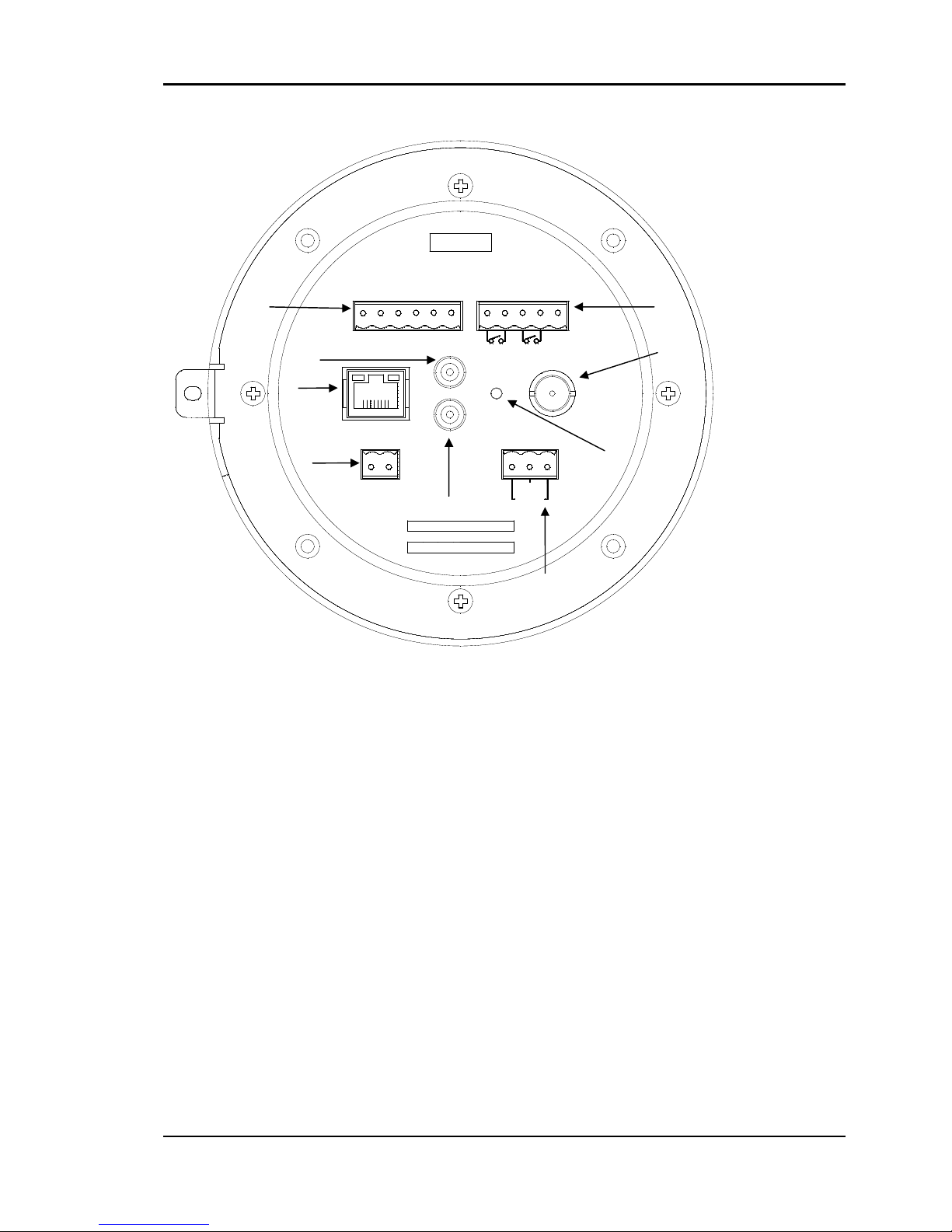
5.CONNECTIONS ...................................................................................................... 13
5.1.Connectors ........................................................................................................................ 13
6.CONFIGURATION .................................................................................................. 18
6.1.Setupnetworkenvironment ............................................................................................ 18
6.2.Viewvideoonwebpage ................................................................................................... 18
6.2.1.ViewvideousingIPAdminTool ................................................................................. 18
6.2.2.ViewvideousingIPaddress ...................................................................................... 21
6.3.Reset................................................................................................................................. 21
6.4.FactoryDefault................................................................................................................. 21
APPENDIX(A):SPECIFICATIONS ................................................................................ 22
Summary ................................................................................................................................. 22
ElectricalCharacteristics ......................................................................................................... 24
EnvironmentCondition ........................................................................................................... 24
VCA(VideoContentAnalysis) ................................................................................................. 25
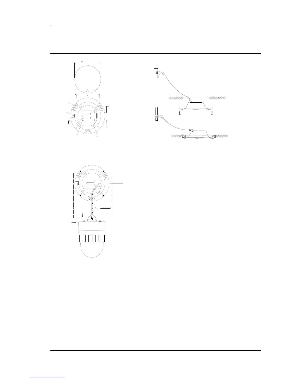
APPENDIX(B):DIMENSIONS..................................................................................... 26
Dome ....................................................................................................................................... 26
OutdoorHousing..................................................................................................................... 27
APPENDIX(C):ACCESSORIES..................................................................................... 28
Outdoorpart ........................................................................................................................... 28
Assemblingoutdoorhousing .................................................................................................. 29
APPENDIX(D):TROUBLESHOOTING......................................................................... 31
CheckingtheFirmware ...............................................................Error!Bookmarknotdefined.
UpgradingtheFirmware .............................................................Error!Bookmarknotdefined.
Support........................................................................................Error!Bookmarknotdefined.
REVISIONHISTORY ................................................................................................... 31

NM‐IP4500
6
1.FEATURES
Camera
•Indoor/OutdoorPTZDomeIPCamera
•IP66vandalproof(supportedonlywithOutdoorHousing)
•Sony1/4”ExviewHADCCD
•x36OpticalZoom,x12DigitalZoom
•TrueDay&Night(IRCutFilter)+DSS
Streaming
•Dualstreamingmode(suchasdifferentcodec/resolution/bitrateandsoon.)
•De‐interlacingonDSP
•Burnt‐intextsupported
•Unicast/Multicastsupported
Video/Audio
•Videocompression:H.264/MPEG/MJPEG,25/30FPS@D1(PAL/NTSC)
•Audiocompression:G.711(µLaw,aLaw)/PCM
•Analogvideooutforexternalmonitors
•VideoMotionDetectionsupported
•2‐waymonoaudiosupported
Network
•RTSP/HTTPprotocolsupported
•10/100Base‐TEthernet
AdditionalFeatures
•RS‐485supported
•OSDsupported
•SDK(SoftwareDevelopmentKit)provided
•4chDI/2chDOsupported
VCA(VideoContentAnalysis)
•VCAPresence(Includedasbasic)
•VCASurveillance(Optional)

NM‐IP4500
7
2.PACKAGECONTENTS
Unpackcarefullyandhandletheequipmentwithcare.Thepackagingcontains:
CameraCeilingMountBracket
CeilingCover Screws
WrenchTerminalblock
(2Pin,3Pin,5Pin,6Pin)
SafetyWire CableTies
QuickInstallationGuide
Note
i
Theabovecontentsaresubjecttochangewithoutpriornotice.

NM‐IP4500
8
3.PARTNAMES
LockScrew
Bubble
LockHolder
DipSwitch
CameraLens
CeilingMountBracketforindoor

NM‐IP4500
9
ALARM AUX
GND 1 2 12
D+
34GND
D- GND
AC24VRS 485
GND
ON VIDEO
OUT
LINE OUT
MIC/
100 BaseT LINE IN
①
②
③
④
⑤
⑥
⑧
⑨
⑦
*Modelshereinandtheirappearance
aresubjecttochangewithoutanyprior
notice.

NM‐IP4500
10
LANConnector(Ethernet)
ThisisaRJ45LANconnectorfor10/100Base‐TEthernet.
RS‐485
ThecamerasupportsRS‐485SerialCommunicationPort.
3pinconnectorforpower
ThecameraneedsanAC24Vforpowersupply.Refertothesection“5.1.Connectors”formorespecific
information.
Externalvideo
Itisananalogvideooutputport.
5pinconnectorforD/I
Thecameraprovides2channelD/I.Refertothesection“5.1.Connectors”formorespecificinformation.
6pinconnectorforD/O
Thecameraprovides4channelD/O.Refertothesection“5.1.Connectors”formorespecific
information.
AudioOutput
Thecamerahasamonoaudiooutput.
AudioInput
Thecamerahasamonoaudioinput.
Reset
ResetswitchisusedforrestartingorresettingthecameraasFactoryDefault(FD).Refertothesection
“6.3.Reset”formorespecificinformation.

NM‐IP4500
11
4.INSTALLATION
Beforeyouinstallthecamera,youshouldset
theDIPswitchestoconfigurethecameraID,
communicationprotocol.Pleaserefertothe
page15.DIPSwitch
1.Findtheplaceswhicharestrongenoughto
supportthecamera,about2kg.
2.Makeahole,Ø147mm,ontheceiling.
3.Hookthesafetywiretosuspensionandthe
safetywireholdonthebracket.
4.Installtheceilingmountbracketbydriving4
screws,Ø4mmtappingscrews.
5.Youcanmakewiressimplebycableties.
SAFETY WIRE
CABLE TIE
LOCK HOLDER 2
MOUNT HOLDER
147.0 mm
COVER HOLE
LOCK HOLDER 1
SAFETY WIRE HOLE MOUNTING HOLE
CELING BRACKET
SCREW(Ø4.0)
AB
C

NM‐IP4500
12
Caution
!
Thecameramayfallofftheceilingevenaftertheproperinstallationand
mounting.Topreventanyaccident,makesuretheceilingisfirmandstable
enoughtosupportthecamera.Ifanyreinforcementisneeded,consultwithyour
safetypersonnelandproceedwiththeinstallation.
4.1.SettingtheImageAttribute
Youcansettheimageattributeofcamerathroughthewebpage.
ThemenuofimageattributecanbeseenunderSetup>Video&Audio>Video‐in>AttributeSetting.
Brightness,contrast,hue,saturationandsharpnesscanbeadjusted.
4.2.OperatingtheOSDMenu
TooperatetheOSDofcamera;refertothe”OSDMenuControlManual”intheSDK.
COVER
HOLE
COVER LOCK
LOCK HOLDER.2
10°
LOCK HOLDER.1
COVER
SCREW
(M3.0)
DE
F
6.Makethewiresgothroughthesquarehole.
7.Insertmountholderandtwistthecamera
counterclockwise.
8.Fixthecamerabydrivingascrewonlock
holder1and2.
9.Installthecoverbyinsertingcoverlockand
twistingclockwise.

NM‐IP4500
13
5.CONNECTIONS
5.1.Connectors
PowerConnection
Please,checkthevoltageandcurrentcapacityofratedpowercarefully.Ratedpowerisindicatedinthe
backofmainunit.
TypeRatedPowerInputVoltageRangeCurrentConsumption
IndoorAC24V18~32VAC850mA
OutdoorAC24V18~32VAC1.5A
RS‐485Communication
ForPTZcontrol,connectthislinetokeyboardandDVR.Tocontrolmultiplecamerasatthesametime,
RS‐485communicationlinesofthemisconnectedinparallel.
AnalogVideoConnection
ConnectwithBNCcoaxialcable.
AudioInput/OutputConnection
ConnecttotheaudioinputdevicesuchasaMicandtheaudiooutputdevicesuchastheamplifier
speaker.
Caution
!
Donotconnectthespeakerwithoutamplifier.
AC220/110V
AC24V
ADAPTOR
SIGNAL
IR SENSOR or DOOR SENSOR
GND
AUX 2
A
UX 1
MONITOR
TERMINAL BLOCK
(
FEMALE
)
D
D
RS 485
ON
LINE OUT
MIC/ LINE IN
100 BaseT
LINE OUT
MIC IN
RS-485 Serial Device
LAN CABLE

NM‐IP4500
14
Sensor(DI)connection
Thecameraprovides4channelD/I.Itcanbeconnectedtoarelaytypesensorasthefollowingfigures.
RelayRating:Max24VAC500mAor12VDC1A
Caution
!
Donotexceedthemaximumrelayrateing.
Alarm(DO)connection
Thecameraprovides2channelD/O.
RelayRating:Max24VAC500mAor12VDC1A
Caution
!
Donotexceedthemaximumrelayrating.
DO
COM
RelayType
Device
Internal
+5V
DI
COM
RelayType
Outputof
Sensor
Internal
+‐

NM‐IP4500
15
DIPSwitch
Beforeyouinstallthecamera,youshouldsettheDIPswitchestoconfigurethecameraID,
communicationprotocol.
71 2 3 4 5 6
ON
8
71 2 3 4 5 6
ON
8
UNLOCK
2 mm
547
86547
ON
21
ON
21
3
3
DIP1 ‐CameraID
DIP2‐ RS485, PTZprotocol,Baudrate
6 8
Placingdomecover
Openingdomecover
Placedomecoverandrotatetotighten
UnlockthescrewRotatethecovertoremove
Lockthescrew

NM‐IP4500
16
CameraIDSetup
123456
ON
ON
78
IDnumberofcameraissetusingbinarynumber.Theexampleisshownbellow.
DIP1
Pin12345678
IDValue1248163264128
Defaultonoffoffoffoffoffoffoff
ex)ID=10offonoffonoffoffoffoff
TherangeofIDis1~255.Donotuse0ascameraID.FactorydefaultofCameraIDis1.
Ifyouwanttocontrolacertaincamera,youmustmatchthecameraIDwithCamIDsettingofDVRor
Controller.
CommunicationProtocolSetup
SelecttheappropriateProtocolwithDIPswitchcombination.
DIP2
Pin12345678
IDValueRS485
Termination
Not
used
Protocol1Protocol2Not
used
Not
used
BaudRate1BaudRate2
DefaultOffOffOffOffOffOffOffOn
Pin1isusedforRS485,100Wtermination.SetONDIP2‐1stofonlythelastloopedcamerafromthe
controller.Evenincaseofonlyonecamera,setONDIP2‐1stofthecamera.
Pin3Pin4Protocol
OFFOFFPelco‐DorPelco‐P
ONONNotused
ONOFFMaxpro
Pin7Pin8BAUDRATE
OFFOFFNotUsed
OFFON2400bps(Pelco‐D)
ONOFF4800bps(Pelco‐P)
ONON9600bps(Maxpro)
TERMINATION
CAM 1 CAM 2 CAM n-1 CAM n

NM‐IP4500
17
‐ IfyouwanttocontrolusingDVRorP/Tcontroller,theirprotocolmustbeidenticaltocamera.
Otherwise,youcannotcontrolthecamera.
‐IfyouchangedcameraprotocolbychangingDIPS/W,thechangewillbeeffectiveafteryoureboot
thecamera.
‐Factorydefaultofprotocolis“Pelco‐D,2400bps,8bit,1stopbit,noparity.”

NM‐IP4500
18
6.CONFIGURATION
6.1.Setupnetworkenvironment
ThedefaultIPaddressofyourIPdeviceis192.168.XXX.XXX.YoucanfindtheavailableIPaddressfrom
theMACaddressofyourdevice.PleasemakesurethedeviceandyourPCareonthesamenetwork
segmentbeforerunningtheinstallation.IfthenetworksegmentbetweenyourPCandthedeviceis
different,changeyourPC’ssettingsasbelow.
IPaddress:192.168.xxx.xxx
Subnetmask:255.255.0.0
6.2.Viewvideoonwebpage
ViewthelivevideoonawebpageusingyourIPdeviceanditsIPaddress.YoucanusetheIPAdminTool
orentertheIPaddressonthewebpage.
6.2.1.ViewvideousingIPAdminTool
IPAdminToolautomaticallysearchesallactivatednetworkencodersandIPcamerasandshowsthe
productname,IPaddress,MACaddressandetc.IPAdminToolisprovidedwithSDKatthefollowingSDK
path.
{SDKroot}\BIN\TOOLS\AdminTool\

NM‐IP4500
19
TousetheIPAdminToolandviewthelivevideoonawebpage:
1. StartIPAdminTool.NamesandinfoofcurrentlyactivatedIPdevicesappearasalist.
2. Right‐clickonthedesireddeviceandselectWebview.
3. SelectContinuetothiswebsiteontheSecurityCertificateAlertpage.
(TheexplanationandcapturedimagesatthismanualaremainlyonthebasisofInternetExplorer
7.0)
4. Clickpop‐upblockedandinstalltheActiveXcontrolbyclickingtheInstallbutton.Youneedto
installtheActiveXfordisplayingtheimages.

NM‐IP4500
20
5. Waitforafewsecondswhilethewebpageloads.Thenthelivevideoisdisplayedonthemain
pageofthewebbrowser.
6. Ifthelivevideoisnotdisplayedand“CannotCreateXMLDOMDocumentInstallMSXML4.0”
messageisshownasbelow,pleasedownloadandInstallfromthelinkbelow.
http://www.microsoft.com/downloads/details.aspx?familyid=3144B72B‐B4F2‐46DA‐B4B6‐
C5D7485F2B42&displaylang=en
(VCALibraryrequiresMSXML4.0librarywhichisanxmlparsermadebyMicrosoft.)

NM‐IP4500
21
6.2.2.ViewvideousingIPaddress
ViewthelivevideoonawebpageusingyourIPdeviceanditsIPaddress.TohavethecorrectIP
addressreadyanduseitonawebpage:
1. ConvertaMACaddresstoanIPaddressorchecktheIPaddressontheIPAdminTool.
(TheMACaddressisattachedonthesideorbottomofthedevice.)
2. OpenawebbrowserandentertheIPaddressofthedevice.
3. ClickContinuetothiswebsiteontheSecurityCertificateAlertpage.
4. Clickpop‐upblockedandinstalltheActiveXcontrol.YouneedtoinstalltheActiveXfordisplayingthe
images.
5. Waitforafewsecondswhilethewebpageloads.Thelivevideoisdisplayed.
6.3.Reset
1. Whilethedeviceisinuse,pressandholdtheResetbutton.
2. ReleasetheResetbuttonafter3seconds.
3. Waitforthesystemtoreboot.
6.4.FactoryDefault
1. Disconnectthepowersupplyfromthedevice.
2. ConnectthepowertothedevicewiththeResetbuttonpressedandheld.
3. ReleasetheResetbuttonafter5seconds.
4. Waitforthesystemtoreboot.
Thefactorydefaultsettingscanbeinferredasfollows:
IPaddress: 192.168.xx.yy
Networkmask: 255.255.0.0
Gateway: 192.168.0.1
UserID: root
Password: pass
MACaddress=00‐13‐23‐01‐14‐B1 →IPaddress=192.168.20.177
theHexadecimalnumbertoDecimalnumber.

NM‐IP4500
22
APPENDIX(A):SPECIFICATIONS
Summary
Theexplanationandspecificationatthismanualaremainlyonthebasisofthespecificcameramodel,
whichusesSony36XOpticalZoommodule.
CameraModule
ImageSensorSony1/4”ExviewHADCCD
EffectivePixelsNTSC768(H)*494(V)380K/PAL752(H)*582(V)440K
TVSystemNTSC/PAL
HorizontalResolutionMoreThan480TVLines
Zoomx36OpticalZoom,x12DigitalZoom
Focallength(F=1.6~4.5,f=3.4to122.4mm)
WhiteBalanceAuto/Manual(Red,BlueGainAdjustable)
ScanningSystem2:1Interlace
SyncSystemInternal(12VDC)
Min.Illumination1.4Lux(50IRE),0.01Lux(ICROn)
Lens(Optical)36xOpticalZoom(F=1.6~4.5,f=3.4to122.4mm)
Lens(Digital)12x(432xwithoptical)
FocusAuto/Manual/SemiAuto
IrisAuto/Manual
Day&NightAuto/Day/Night(ICR)
DigitalSlowShutterOn/Off
LuminanceS/NRatioMorethan50dB(AGCoff)
AGCNormal/High/Off
BLCOn/Off
FlickerlessOn/Off
SSNRLow/Middle/High/Off
PAN/TILT
PanRotationAngle360°QuickEndlessRotation
Manual0.5°~100or200°/sec(64step)
PanSpeedPresetMax300°/sec,Min10°/sec
TiltRotationAngle ‐2°~90°
Manual0.5°~45°/sec(64step)
TiltSpeedPresetMax250°/sec,Min200°/sec
SystemAccuracy0.024°
Dome
Preset165positionswith16characterlabels/
Independentpresetcharacteristicsetup
Table of contents
Other Mitsubishi Security Camera manuals
Popular Security Camera manuals by other brands

Honeywell
Honeywell HCM574L Specifications

360 Vision
360 Vision Eclipse HD Stainless Steel Installation & configuration manual

Vista
Vista VBC-800NI30-WC user guide

Security Camera King
Security Camera King TVIVD-PR5EXIR28 user manual

bauhaus
bauhaus WT816 quick guide

RoadHawk
RoadHawk 1080P High Performance Forward Facing Camera user manual