Mitsubishi VL-100U-E User manual

−1−
English
HOME USE LOSSNAY
TYPE
VL-100U-E
Installation Instructions
9701R870HH9001
Contents Page
(For Dealer or Contractor)
Before proceeding with the installation work, be sure to read through these instructions.
The installation work should be done by an authorized dealer or qualified contractor.
Please ensure that the separate “Operating Instructions” are handed over to the customer.
Essential safety precautions
•Before proceeding with operation, please be sure to read
“Essential Safety Precautions” as it will tell you how to operate
the product properly and safely.
•The displays have the following significance.
•The graphic symbols have the following significance.
This applies to mishandling or
misoperation of the product
which may lead to a fatal or
serious injury.
This applies to mishandling or
misoperation of the product
which will lead to an injury or
damage to your home,
household effects, etc.
WARNING
CAUTION
Safety precautions
…………… 2
Outline drawings……………… 2
Installation positions …………3
Before installation
· Unpacking …………………… 4
· Wall hole construction……… 5
· Preparations
before installation ……… 5
· If the wall is more than
300 mm thick ……………… 6
· Installing
the mounting plate ……… 6
· Installing the main unit …… 6
· Outdoor construction ……… 7
Installing the unit
Test run ………………………… 8
Test run
Prohibited
Do NOT
disassemble.
Use is prohibited
wherever water is
present.
You must follow the
instructions given.
Disconnect the
power plug.
英/Installation 08.11.25 5:17 PM ページ1

−2−
English
Before installation
WARNING
•Do not alter the unit or disassemble it more than necessary.
(Fire, electric shock or injury may result.)
•Do not install the unit in a bathroom or other highly humid location.
(Fire or electric shock may result.)
•Use the unit at the rated voltage and within the control capacity range.
(Failure to do so may result in fire or electric shock.)
•Make sure the outside air intake opening is positioned so that it will not take in
combustion gases or other exhaust. Position the unit so that it will not become covered
with snow. (If intake air is not fresh, oxygen may become depleted in the room.)
•Install the unit securely to a sufficiently strong wall surface.
(Injuries may result if the unit falls.)
•Install the unit only on a wall. Do not install it on a ceiling.
(Injuries could result if the unit falls.)
•Do not install the unit in excessively hot areas, areas of oily smoke, or near open flames
(Fire may result).
•Wear gloves when attaching the unit (or injury may result).
•Attach the unit so that the air supply/exhaust pipes slope downward toward outdoors.
(Rainwater entering the unit could cause electric shock or fire, or wet indoor items.)
•Install the supplied outdoor weather covers.
(Rainwater entering the unit could cause electric shock or fire, or wet indoor items.)
•After installation, be sure to remove the power plug from the wall outlet when not using
the unit for an extended period. (Failure to do so could cause insulation deterioration, resulting in
electric shock or fire from a short-circuit.)
CAUTION
620
176
86 168
265
168 106
75
245×600
φ150
5°
250 30
Fresh air supply grille
Power cord
Indoor air exhaust grille
Shutter knob Shutter open
position
Shutter closed
position
Operation
indicator
Cord
Air supply/exhaust pipe
Outer diameter
φ75×2
Outdoor
weather cover
Wall
thickness
50 to 300
(Unit: mm)
If the wall is thicker than 300 mm, use the extension pipes
and the pipe extension joints (separately sold parts).
Safety precautions
Outline drawings
英/Installation 08.11.25 5:17 PM ページ2

−3−
English
200
420
350
530
554
620
360 360
233
87
163
95.5
15 25
95 119
108 20×10=200
238.5
265
13.5
40
267.5 292
75 75
Mounting plate Edge of
main unit
(Adjustable)
min.
Position of screw for
securing unit horizontally Air exhaust hole
(φ80 to φ90 wall hole) Air intake hole
(φ80 to φ90 wall hole)
(Min.)
(Max.)
min. (Unit: mm)
(Adjustable)
Position of
screw for
securing unit
horizontally
min. min.
Pitch (Adjustable)
Require to
be secured Mounting hole
36 –φ6Require to
be secured
WHITE
BLUE
BLUE
BROWN
BROWN
L
NRED
BLUE
BROWN
GREEN/YELLOW
AC
220-240V 50Hz
220V 60Hz 0.4
2
13
NEON LAMP
BLUE
RED
R
E
D
WHITE
BLACK PINK
BLACK BLACK
Installation positions
英/Installation 08.11.25 5:17 PM ページ3

−4−
English
Installing the unit
Unpacking
Pipe mounting plates: 2
Weather covers: 2
Flange nuts: 2
Weather cover
mounting plate: 2
Screws for securing
weather covers: 4
Wood screws: 10
(For attaching mounting plate/for securing
main unit horizontally)
Remove mounting plate.
•Remove two screws for se-curing
main unit.
Air supply/exhaust pipes: 2
Aluminum tape: 2 packets
Screws for securing main unit: 2
Mounting plate
Main unit
Note
•Keep the screws for securing the main unit in a safe place. Screws are needed when installing the main unit.
英/Installation 08.11.25 5:17 PM ページ4

−5−
English
Determine the installation position.
1. Place the mounting plate on the wall.
2. Check that the reinforcement (indoor wall) is
positioned properly to secure the mounting plate.
3. Attach the mounting plate loosely (with single wood
screw).
Determine the position of the wall holes.
1. Place a caliper on the calibrations on the mounting
plate.
2. Mark the center position of the wall hole.
•Position the wall holes away from obstructions in
the wall, within the ranges shown in the table
below.
Drill the wall holes.
1. Remove the mounting plate.
2. Drill wall holes of φ80 to φ90 mm.
•To prevent rainwater entering indoors, drill the
holes so they slope downward toward outdoors.
Secure air supply/exhaust pipes to mounting
plate.
1. Insert pipe into mounting plate.
2. Rotate pipe counterclockwise.
3. Secure flange (four catches).
Cutting air supply/exhaust pipes.
1. Measure the wall thickness.
2. Cut the pipes to a length of [wall thickness] + 30
mm.
•Be sure to cut off the end without the flange.
1
2
3
1
2
Wall
Indoors
Indoors
Wall hole
5°
Outdoors
Outdoors
Lossnay element
Air supply/exhaust pipe
Cut here.
Wall
thickness 30mm
Before installation After installation
Catch Air supply/exhaust pipe Pipe mounting
plate
Catch
Under
Under
Wall hole construction
Preparations before installation
Note
Note
Exhaust pipe Air supply pipe
Air supply/exhaust
hole position hole position pipe hole pitch
Vertical From main unit center
–
direction 15 mm below to 25 mm above
Horizontal
From main unit From main unit
direction center to left center to right 200 to 350 mm
85 to 175 mm 85 to 175 mm
83 mm min.
44 mm min.
113 mm min. (from
nearest obstruction) Mounting plate
Reinforcement
83 mm min.
Wood screw
(for loose
attachment)
Air supply/exhaust pipe hole pitch
Calibrations
Exhaust pipe hole center Air supply pipe
hole center
英/Installation 08.11.25 5:17 PM ページ5

−6−
English
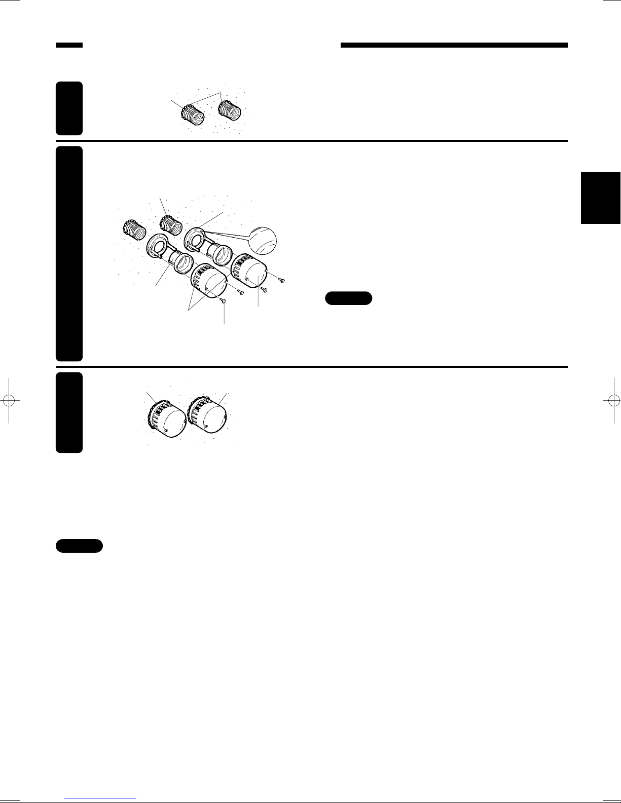
Use the extension pipes (separately sold Parts P-100P-E) and pipe extension joints (separately sold Parts
P-100PJ-E). Attach them to the pipes as shown below. (Each set can extend the pipes by 300 mm.)
1
2
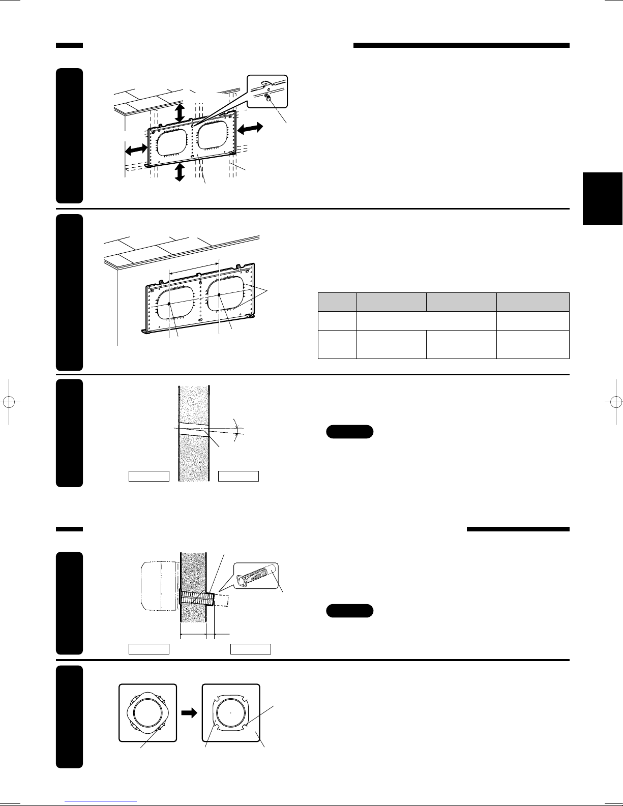
Secure air supply/exhaust pipes.
Secure main unit.
1. Hang main unit on mounting plate.
2. Secure main unit with the two screws provided.
(Press main unit into wall.)
1. Pass the air supply/exhaust pipes through the wall
holes. (The “under” mark should be on the bottom.)
2. Secure the pipes with aluminum tape.
Screw
(for loose attachment)
Wood screw
Pipe mounting
plate
Aluminum tape
“Under” mark
Air supply/exhaust pipe
Wall hole
1. Screw the extension joints all the way into the air
supply/exhaust pipes, making sure they fit securely.
2. Screw the extension pipes all the way into the
extension joints, making sure they fit securely.
3. Cut the pipes to a length of [wall thickness] + 30 mm.
Before screwing the extension joints into
the pipes, apply caulking (commercially
available) to the O-rings on the joints (to
prevent condensation inside the pipes
wetting the indoor wall).
Secure mounting plate.
•Secure the mounting plate to the wall (using seven
wood screws and the single screw for loose
attachment).
•You can align the plate horizontally by suspending
a weight from the top and aligning its string with the
center line.
•Be sure to secure the mounting plate with the two
screws near the catches, and with screws in
symmetrical positions.
•To attach the plate to a concrete wall, use concrete
screws to secure it (commercially available).
If the wall is more than 300 mm thick
Installing the mounting plate
Installing the main unit
Note
O-ring
Caulking
Extension joint
(P-100PJ-E)
Extension pipe
(P-100P-E)
Mounting
plate
Be sure to secure. Weight
•Install the air supply/exhaust pipes so that
they slope downward toward outdoors.
(Rainwater entering the unit may cause electric
shock or fire, or wet indoor items.)
Main unit Square
hole Catch
Screw for securing
main unit Mounting plate
Note
Quantity Requirement
2 sets of P-100P-E for 1 VL-100U-E
1 set of P-100PJ-E for 1 VL-100U-E
CAUTION
Under
Under
英/Installation 08.11.25 5:17 PM ページ6

−7−
English
1
2
3
Attach weather covers packed together with unit.
•To keep the air supply and exhaust sides separate,
each weather cover attaches only to one side.
Check that each “cap” area is positioned on the left,
as shown in the diagram.
Air supply/exhaust pipe Caulking
Flange nut
“Cap”area
UPPER
Weather cover
Caulking Weather cover
Wall hole caulking
•Fill in any gaps between the air supply/ exhaust
pipes and the wall holes with caulking
(commercially available).
Attaching weather covers
1. Insert weather cover mounting plate into air
supply/exhaust pipes.
2. Tighten flange nuts. (Secure so that “upper” marks
on flanges are on top.)
To prevent rainwater leakage
•Caulk any gaps around the weather covers.
•After installing the unit, before conducting a test run, check the unit again to make sure it has been installed
correctly.
•Be sure to correct any problems discovered. (Failure to correct problems may result in poor performance as well as causing
safety problems.)
•Weather cover mounting plate have two holes (φ
5mm) in them. Use these holes to secure the
flanges to the wall.
3. Secure the weather covers with the screws.
Outdoor construction
Note
Note
Weather cover
mounting plate
Air supply/exhaust pipe
Screw for securing
weather cover
英/Installation 08.11.25 5:17 PM ページ7

−8−
English
Insert the power plug into the wall outlet.
Check the shutter’s open/close operation.
•Slide the knob to check the shutter opens and
closes normally.
Check there are no strange vibrations or noises.
•Stop the unit after checking.
Close the shutter.
•Slide the knob to the shutter closed position.
Remove the power plug from the wall outlet.
Check operating modes.
1. Slide the knob to the shutter open position.
2. Pull the cord to start operation.
3. Pull the cord a few more times to check the unit
responds accordingly.
1
2
3
4
6
5
Test run
Knob
Open
Closed
Closed
Open
Cord
Operation indicator
Once
HI operation
(Operation indicator lights.)
LO operation
(Operation indicator goes out.)
Knob
Close Close
Off
Twice Three
times
英/Installation 08.11.25 5:17 PM ページ8
Table of contents
Popular Ventilation Hood manuals by other brands

Hotpoint
Hotpoint PHBS 9.8C LTD K Instructions for use

ROBINHOOD
ROBINHOOD RPC3CL52SS/MB Installation and operating instructions

Amica
Amica OMP6253BG operating instructions

ROBLIN
ROBLIN LAGOON 900 Dimensions

Jenn-Air
Jenn-Air 32" Installation Instructions and Use & Care Guide

Hotpoint
Hotpoint HTS93G user manual