MityCAM MityCAM-B2521 User manual

60-000007
May 12, 2015
www.criticallink.com
MityCAM-B2521 and
MityCAM-B1910 User Manual

MityCAM-B1910/B2521 User’s Manual
Page 2 of 27 60-000007
May 12, 2015
www.criticallink.com
Contents
1 Introduction.................................................................................................................................................... 5
1.1 Additional Documentation ....................................................................................................................................... 5
1.2 Vocabulary ................................................................................................................................................................ 5
1.3 Important Differences .............................................................................................................................................. 5
1.3.1 Sensor Size ............................................................................................................................................................. 5
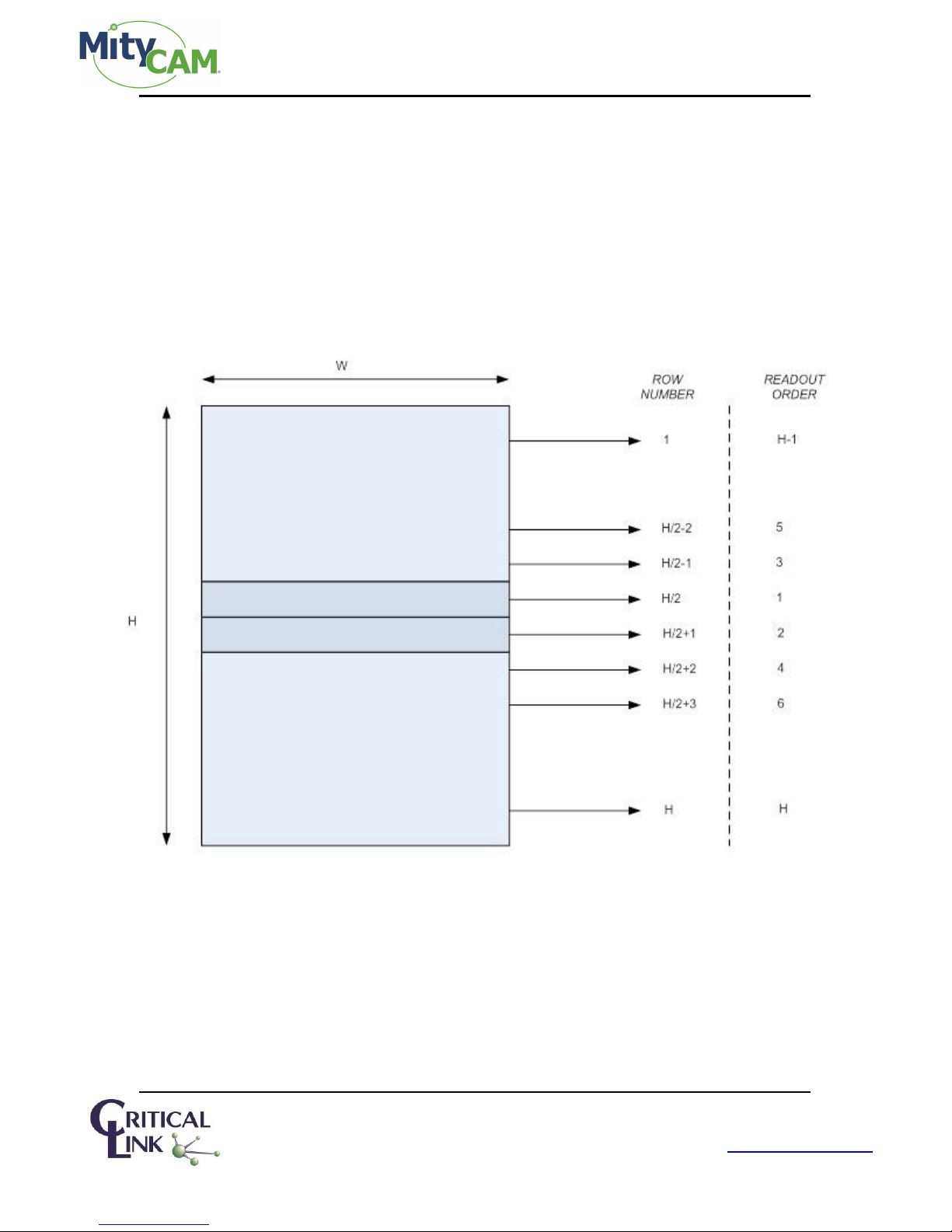
1.3.2 Sensor Readout Order ........................................................................................................................................... 6
1.3.2.1 MityCAM-B1910 ................................................................................................................................................. 6
1.3.2.2 MityCAM-B2521 ................................................................................................................................................. 6
2 Continuous High Speed Operation via Camera Link........................................................................................... 7
2.1 Expanded 8-bit Mode (8 bit x 10 pixels) ................................................................................................................... 7
2.2 Expanded 16-bit Mode (16 bit x 5 pixels) ................................................................................................................. 7
2.3 Base 8-bit Mode (8 bit x 2 pixels) ............................................................................................................................. 7
2.4 Base 16-bit Mode (16 bit x 1 pixel) ........................................................................................................................... 8
2.5 Base 12-bit Mode (12 bit x 2 pixels) ......................................................................................................................... 8
3 Region of Interest............................................................................................................................................ 8
3.1 Restrictions ............................................................................................................................................................... 8
3.1.1 MityCAM-B2521..................................................................................................................................................... 8
3.1.2 MityCAM-B1910..................................................................................................................................................... 8
3.2 MityViewer Restrictions............................................................................................................................................ 9
3.3 Important Note ......................................................................................................................................................... 9
4 Exposure & Frame Interval Time ...................................................................................................................... 9
4.1 Frame Interval........................................................................................................................................................... 9
4.2 Exposure ................................................................................................................................................................. 10
4.3 Configuring.............................................................................................................................................................. 10
4.3.1 Camera Link ......................................................................................................................................................... 10
4.3.2 MityViewer .......................................................................................................................................................... 11
5 SCLK.............................................................................................................................................................. 12
6 GPIOs............................................................................................................................................................ 12
6.1 Input........................................................................................................................................................................ 12
6.1.1 Camera Link ......................................................................................................................................................... 12
6.1.2 MityViewer .......................................................................................................................................................... 13
6.2 Output..................................................................................................................................................................... 13
6.2.1 Camera Link ......................................................................................................................................................... 14
6.2.2 MityViewer .......................................................................................................................................................... 14
7 External Trigger ............................................................................................................................................. 14
7.1 Timing Characteristics............................................................................................................................................. 14
7.1.1 Rolling Shutter ..................................................................................................................................................... 14
7.1.2 Global Shutter...................................................................................................................................................... 14
7.2 Configuration .......................................................................................................................................................... 16
7.2.1 Camera Link ......................................................................................................................................................... 16
7.2.2 MityViewer .......................................................................................................................................................... 17
8 Shutter Strobe............................................................................................................................................... 19
8.1 Rolling Shutter ........................................................................................................................................................ 19
8.1.1 Internal Trigger .................................................................................................................................................... 19
8.1.2 External Trigger.................................................................................................................................................... 19

MityCAM-B1910/B2521 User’s Manual
Page 3 of 27 60-000007
May 12, 2015
www.criticallink.com
8.2 Global Shutter......................................................................................................................................................... 20
8.3 Configuring.............................................................................................................................................................. 20
8.3.1 Mity Viewer.......................................................................................................................................................... 20
8.3.2 Camera Link ......................................................................................................................................................... 21
9 Camera Link .................................................................................................................................................. 22
9.1 Camera Link Configuration ..................................................................................................................................... 23
9.1.1 Camera Link Output Mode .................................................................................................................................. 23
10 MityCAM-B2521 Specific Configurations....................................................................................................... 23
10.1 Pseudo-One Port Mode ........................................................................................................................................ 23
10.1.1 Limitations ......................................................................................................................................................... 24
10.1.2 Configuration ..................................................................................................................................................... 24
11 MityCAM-B1910 Specific Configurations....................................................................................................... 24
12 Network Configuration ................................................................................................................................ 24
13 Firmware Upgrade....................................................................................................................................... 25
14 Connecting via RNDIS to a Windows PC........................................................................................................ 26
15 Revision History........................................................................................................................................... 27
Figures
Figure 1 MityCAM-B2521 Readout Order.....................................................................................................................6
Figure 2 Potential Leakage / Blooming with Reduced Vertical ROIs ............................................................................9
Figure 3 CIS Snapshot Control Window ......................................................................................................................11
Figure 4 Update GPIO Pin States ................................................................................................................................13
Figure 5 Global Shutter Exposure (Exposure less than ROI Height+16 row times) ....................................................15
Figure 6 Global Shutter Exposure (Exposure greater than ROI Height+16 row times) ..............................................15
Figure 7 Global Shutter Exposure is sampled on a row time (1 row of jitter possible)..............................................15
Figure 8 MityViewer CIS Calibration Window Configured for External Trigger..........................................................17
Figure 9 MityViewer Log Window for Trigger Configuration......................................................................................17
Figure 10 MityViewer Snapshot Control Window, Configure for Continuous Capture..............................................18
Figure 11 Shutter Strobe Timing in Rolling Shutter Mode..........................................................................................19
Figure 12 Strobe to Exposure Delay (1 row time).......................................................................................................19
Figure 13 “Shutter” Strobe Selection in MityViewer GPIO Configuration..................................................................21
Figure 14 Network Configuration Webpage...............................................................................................................25
Figure 15 Typical Windows USB RNDIS Adapter Properties......................................................................................26
Figure 16 Internet Protocol Version 4 Properties Box................................................................................................26
Figure 17 Static IP configuration Settings ..................................................................................................................27
Tables
Table 1 Reference Documentation...............................................................................................................................5
Table 2 Steps to Enter 8x10 Expanded Camera Link ....................................................................................................7
Table 3 Steps to Enter 16x5 Expanded Camera Link ....................................................................................................7
Table 4 Steps to Enter 8x2 Base Camera Link...............................................................................................................7
Table 5 Steps to Enter 16x1 Base Camera Link.............................................................................................................8
Table 6 Steps to Enter 12x2 Expanded Camera Link ....................................................................................................8

MityCAM-B1910/B2521 User’s Manual
Page 4 of 27 60-000007
May 12, 2015
www.criticallink.com
Table 7 Range of Frame Interval Times ........................................................................................................................9
Table 8 Allowed Exposure Times ................................................................................................................................10
Table 9 Row Times per SCLK frequencies for 1910 and 2521 Cameras......................................................................12
Table 10 GPIO Modes .................................................................................................................................................12
Table 11 Camera Link GPIO output configuration commands ...................................................................................14
Table 12 Global Shutter Timing Parameters...............................................................................................................15
Table 13 Camera Link Commands for Configuring GPIO to Generate Shutter Strobe ...............................................21
Table 14 Maximum Supported SCLK Rates for Different Camera Link Output Modes ..............................................22
Table 15 Maximum Supported Frame Rates for Different Camera Link Modes ........................................................22
Table 16 Minimum Exposure Time as a Function of Output Camera Link Mode.......................................................22
Table 17 Required Camera Link Commands to Enter a Given Camera Link Output Mode ........................................23
Table 18: Pseudo-One Port Mode Commands ...........................................................................................................24
Table 19: Row-Interleaved Mode Commands ............................................................................................................24
Table 20 Factory Default Network Address Settings ..................................................................................................24

MityCAM-B1910/B2521 User’s Manual
Page 5 of 27 60-000007
May 12, 2015
www.criticallink.com
1Introduction
The purpose of this document is to outline the specific features of the MityCAM-B1910 and MityCAM-B2521
cameras.
1.1 Additional Documentation
In addition to this document, the following documents are also useful / pertinent to the use and operation of the
MityCAM-B1910 and MityCAM-B2521 cameras.
Table 1 Reference Documentation
Document #
Title
Description
60-000004
MityCAM-B1910 Camera Link
Interface Document
Provides complete application programmer interface
information for serial command port of Camera Link
interface for MityCAM-B1910.
60-000005
MityCAM-B2521 Camera Link
Interface Document
Provides complete application programmer interface
information for serial command port of Camera Link
interface for MityCAM-B2521.
60-000008
MityCAM Camlink Panel User
Guide
MityCAM Cam Link Panel User Guide
P-10281
MityCAM Firmware Upgrade
Procedure
Provides description of steps needed to upgrade
MityCAM firmware.
1.2 Vocabulary
Sensor –The sCMOS sensor on the headboard of the camera hardware stack.
Row –One complete row of pixels output from the sensor.
SCLK –The clock provided by the SoC Processor board to the sensor for it to operate. There are a fixed number of
SCLK values supported by the camera.
Row time –A fixed number of SCLK periods which includes time to shift and convert charge as well as read out the
data from the sensor. Integral multiples of “row time” is the basic unit of time recognized by the sensor.
1.3 Important Differences
1.3.1 Sensor Size
The primary difference between the two sensors is their maximum resolution.
Maximum 2521 ROI Height = 2160 rows
Maximum 1910 ROI Height = 1080 rows
The 2521 sensor has two halves, a top and bottom half each with 1080 rows which operate in parallel, making the
timing very similar for both sensors. Because of this difference for MityCAM-B2521, ROIHeight should be divided by
2 from the output image’s height when considering timing in the tables in the following sections.

MityCAM-B1910/B2521 User’s Manual
Page 6 of 27 60-000007
May 12, 2015
www.criticallink.com
1.3.2 Sensor Readout Order
1.3.2.1 MityCAM-B1910
This is a raster order camera. Rows are output from the top of the sensor down (or from the bottom up). Most
frame grabbers should be able to handle this method of data output.
1.3.2.2 MityCAM-B2521
Normal operation for the camera is to read from the center out. The result is data being output row by row,
interleaved, from the center of the sensor out. For maximum frame-rate, the frame grabber must perform the
unwinding of the interleaved rows.
Figure 1 MityCAM-B2521 Readout Order
The camera can also be configured to output in raster order. For information on this mode and the limitations on
the camera, see section 10.1 “Pseudo-One Port Mode.”

MityCAM-B1910/B2521 User’s Manual
Page 7 of 27 60-000007
May 12, 2015
www.criticallink.com
2Continuous High Speed Operation via Camera Link
This section details setting up full resolution, high speed operation in each Camera Link configuration. Pay careful
attention to the clock and frame intervals that are being set. Failure to set an appropriate clock or frame interval
will overflow the FPGA with sensor data resulting in undefined output.
For each mode, SCLK must be adjusted. Please reference “Table 14 Maximum Supported SCLK Rates for Different
Camera Link Output Modes” in Section 9.
2.1 Expanded 8-bit Mode (8 bit x 10 pixels)
This mode offers the highest continuous frame-rate possible.
Table 2 Steps to Enter 8x10 Expanded Camera Link
Step
Command
Comment
1
<SOMD 0>
Go to expanded Camera Link output
2
<SBPP 0>
Go to 8 bpp output
3
<SCLK n>
See Table 14 in Section 9 for maximum SCLK.
4
<SFIT 0>
Set the frame-rate to the maximum supported
5
<STRT>
Begin continuously capturing
2.2 Expanded 16-bit Mode (16 bit x 5 pixels)
This mode offers the highest continuous frame-rate possible while outputting all of the sensor data.
Table 3 Steps to Enter 16x5 Expanded Camera Link
Step
Command
Comment
1
<SOMD 0>
Go to expanded Camera Link output
2
<SBPP 1>
Go to 16 bpp output
3
<SCLK n>
See Table 14 in Section 9 for maximum SCLK.
4
<SFIT 0>
Set the frame-rate to the maximum supported
5
<STRT>
Begin continuously capturing
2.3 Base 8-bit Mode (8 bit x 2 pixels)
This mode offers the highest continuous frame-rate possible.
Table 4 Steps to Enter 8x2 Base Camera Link
Step
Command
Comment
1
<SOMD 1>
Go to Base Camera Link output
2
<SBPP 0>
Go to 8 bpp output
3
<SCLK n>
See Table 14 in Section 9 for maximum SCLK.
4
<SFIT 50000>
Set the frame-rate to the maximum supported
5
<STRT>
Begin continuously capturing

MityCAM-B1910/B2521 User’s Manual
Page 8 of 27 60-000007
May 12, 2015
www.criticallink.com
2.4 Base 16-bit Mode (16 bit x 1 pixel)
This mode offers the highest continuous frame-rate possible.
Table 5 Steps to Enter 16x1 Base Camera Link
Step
Command
Comment
1
<SOMD 1>
Go to Base Camera Link output
2
<SBPP 1>
Go to 16 bpp output
3
<SCLK n>
See Table 14 in Section 9 for maximum SCLK.
4
<SFIT 0>
Set the frame-rate to the maximum supported
5
<STRT>
Begin continuously capturing
2.5 Base 12-bit Mode (12 bit x 2 pixels)
This mode offers the highest continuous frame-rate possible.
Table 6 Steps to Enter 12x2 Expanded Camera Link
Step
Command
Comment
1
<SOMD 1>
Go to Base Camera Link output
2
<SBPP 2>
Go to 12 bpp output
3
<SSQRT 1>
Enable square root compression from 16 to 12 bits.
4
<SCLK n>
See Table 14 in Section 9 for maximum SCLK.
5
<SFIT 0>
Set the frame-rate to the maximum supported
6
<STRT>
Begin continuously capturing
When exiting this mode, ensure that <SSQRT 0> is applied to disable the square root compression.
3Region of Interest
The region of interest is configurable between the sensors with some limitations.
3.1 Restrictions
The shared restrictions of ROI:
-ROI height must be an integer multiple of the vertical binning value
-ROI width must be an integer multiple of the horizontal binning value
-ROI width must be an integer multiple of 16
3.1.1 MityCAM-B2521
The maximum resolution of the sensor is 2560x2160.
The specific restrictions for the 2521:
-Start column must be even
-ROI must be centered on the middle row (columns don’t need to be centered; only rows)
-ROI height must be even
3.1.2 MityCAM-B1910
The maximum resolution of the sensor is 1920x1080.
There are no other specific restrictions for the MityCAM-B1910.

MityCAM-B1910/B2521 User’s Manual
Page 9 of 27 60-000007
May 12, 2015
www.criticallink.com
3.2 MityViewer Restrictions
The ROI must meet the above specified requirements when using the MityViewer.
3.3 Important Note
Rolling shutter starts exposure by sending a reset pointer row-by-row through the selected area. After some
amount of time, the rows are read out. When rows are not reset/read out, they will continue to accumulate
charge. Over time, with a reduced vertical ROI (such as requesting 1000 active rows for readout), the remaining
active rows (which are NOT being read out) will saturate and bloom into the area being readout. This results in
pixels of greater magnitude around the horizontal edge of the imaging area as in the example below:
Figure 2 Potential Leakage / Blooming with Reduced Vertical ROIs
4Exposure & Frame Interval Time
Exposure and Frame Interval are integral multiples of “row times” from the sensor. Use the table in the section 5
“SCLK” to convert these row times to time values. Limits on exposure and frame interval times are sensitive to
the shutter mode (rolling vs. global) as well as triggering mode (internal vs. external).
4.1 Frame Interval
The Frame interval is dependent on the triggering method of the camera as well as the shutter mode. For
external triggering, the maximum frame interval time is set by the trigger input. For internal triggering, the
maximum frame interval time is defined by Table 7. For both internal and external triggering, the minimum
frame times are defined by the values in Table 8.
Table 7 Range of Frame Interval Times
Minimum Frame Interval (row times)
Maximum Frame Interval (row times)
Rolling Shutter
Global Shutter
Rolling Shutter
Global Shutter
ROIHeight
(ROIHeight + 17)*2
262143 + ROIHeight
(ROIHeight + 262143)*2

MityCAM-B1910/B2521 User’s Manual
Page 10 of 27 60-000007
May 12, 2015
www.criticallink.com
4.2 Exposure
For a given Frame Interval of N row times, the exposure time must be limited according to Table 8. For externally
triggered modes, N must be limited to be less than 262143 + ROIHeight.
Table 8 Allowed Exposure Times
Frame Interval (rows)
Minimum Exposure (row times)
Maximum Exposure (row times)
Rolling Shutter
Global Shutter
Rolling Shutter
Global Shutter
N
1
1
N - 1
N –(ROIHeight + 17)
4.3 Configuring
Exposure and frame interval can only be set when the camera is not actively capturing. The interfaces take
exposure as a time. Time is then converted to the nearest integral number of row times. Make sure to note the
units when setting these times.
4.3.1 Camera Link
The resolution of the Camera Link interface is microseconds.
Set exposure using the <SEXP time> command.
Set frame interval using the <SFIT time> command.
To guarantee correctly set time, exposure and frame interval should be set in the following manner:
If the desired exposure is longer than the current frame interval can support, set the frame interval to be
longer first, then set the exposure.
If the desired frame interval is shorter than the current exposure requires, set the exposure shorter first,
then set the frame interval.

MityCAM-B1910/B2521 User’s Manual
Page 11 of 27 60-000007
May 12, 2015
www.criticallink.com
4.3.2 MityViewer
The resolution of time in MityViewer is milliseconds.
Adjust the values using the boxes provided on the CIS Snapshot Control window:
Figure 3 CIS Snapshot Control Window
The frame interval takes precedence when setting values. If exposure is configured for 500ms, and the interval is
configured for 100ms, the exposure will be reduced to support the 100ms frame interval.

MityCAM-B1910/B2521 User’s Manual
Page 12 of 27 60-000007
May 12, 2015
www.criticallink.com
5SCLK
There are a fixed number of SCLK frequencies available. These SCLK values directly impact the row time.
There are 2624 SCLK cycles per row for the MityCAM-B2521. There are 2464 SCLK cycles per row for the
MityCAM-B1910.
Use the table below to convert the number of rows into a row time.
The Camera Link interface allows programming the SCLK intervals for both the 1910 and 2521 cameras. By default
is uses the 200 MHz clock rate for 10-tap modes of operation. The MityViewer selects 200 MHz for rolling shutter
operation and 80 MHz for global shutter operation.
Table 9 Row Times per SCLK Frequencies for 1910 and 2521 Cameras
SCLK (MHz)
MityCAM-B1910 Row Time (us)
MityCAM-B2521 Row Time (us)
30
82.13
87.47
40
61.6
65.6
80
30.8
32.8
200
12.32
13.12
6GPIOs
There are 4 general purpose IOs that can be used. The available modes of operation for them are listed in the
table below:
Table 10 GPIO Modes
#
Mode
1.
Input for reading
2.
Output driven low
3.
Output driven high
4.
Input for external trigger (See section 7 “External Trigger”)
5.
Output driven as shutter strobe (See section 8 “Shutter Strobe”)
This section will cover Modes 1, 2 and 3. Modes 4 and 5 are covered in separate sections.
All inputs/outputs are TTL 5V logic.
6.1 Input
In the input mode of operation, the pin can be queried for its current logical value (High or Low).
6.1.1 Camera Link
Issue <GETP>. The result will be a hex value representing each pin value, as a bit-mask, which was read back. Each
bit represents the IO it belongs to (Bit 2 IO 2’s state).
For example, if the response is <ACK><A>, then IO 0 and IO 2 are presently low; IO 1 and IO 3 are presently high.

MityCAM-B1910/B2521 User’s Manual
Page 13 of 27 60-000007
May 12, 2015
www.criticallink.com
6.1.2 MityViewer
To place a pin in Input mode, select “In” from the drop down selection box.
To read back the current state, press “Update.” Pins which are being driven high are denoted with an “x” pins
which are low are left blank.
Figure 4 Update GPIO Pin States
From left to right, the state is reported as Pin 1, Pin 2, Pin 3 and Pin 4.
6.2 Output
In output mode, the pin can be driven high or low. This can be used to toggle a light source or some other
operation.

MityCAM-B1910/B2521 User’s Manual
Page 14 of 27 60-000007
May 12, 2015
www.criticallink.com
6.2.1 Camera Link
Issue the following commands to drive a pin to high/low:
Table 11 Camera Link GPIO Output Configuration Commands
#
Command
Meaning
1
<SETD N 1>
Set the pin direction of IO N to 1 (output)
2
<SETP N 1/0>
Drive IO N to logic 1 (high) or logic 0 (low)
6.2.2 MityViewer
To drive an output high or low, select the “High” or “Low” options in the pin selection drop down. The pin will be
immediately requested to that state.
7External Trigger
External trigger can be used to synchronize the camera’s start of exposure to an external event.
A few items to note about external triggering are noted below:
External trigger is available for both Rolling and Global shutter
External trigger works on CamIO0 (MityViewer Pin 1)
External trigger looks for the rising edge; exposure duration is set in software
IMPORTANT: Remember, for MityCAM-B2521, due to sensor architecture, ROIHeight is ½ the configured height.
7.1 Timing Characteristics
Exposure duration is set according to the section “4.2 Exposure.” Exposure begins as specified in the sections
below.
7.1.1 Rolling Shutter
Upon detection of a rising edge, a rolling reset frame will be started. Exposure will continue for the duration
configured. When exposure is complete, the frame will be read out.
The external trigger pulse width should be at least one row time wide, and less than the number of row times in
the configured ROI. For MityCAM-B2521, that is ½ the number of rows in the ROI height.
7.1.2 Global Shutter
To maximize the potential trigger frequency supported by the camera and due to sensor control requirements,
exposure begins and ends at different times depending on the length of exposure. The sensor operates on a time
scale of row times which correspond to a fixed number of clock ticks. The number of clock ticks depends on the
sensor.

MityCAM-B1910/B2521 User’s Manual
Page 15 of 27 60-000007
May 12, 2015
www.criticallink.com
Figure 5 Global Shutter Exposure (Exposure less than ROI Height+16 row times)
Figure 6 Global Shutter Exposure (Exposure greater than ROI Height+16 row times)
Figure 7 Global Shutter Exposure is Sampled on a Row Time (1 row of jitter possible)
Table 12 Global Shutter Timing Parameters
Label
Min
Typical
Max
Units
Ttrig
1
ROIHeight
Row Times
Tmin
1
1
1
Row Times
Tmax
Tmin
Tmin + 1
Row Times
Tjitter
0
1
Row Times
Texp is the configured exposure time. There is no minimum, and the maximum is currently 262143 rows. If longer
exposures are needed, SCLK can be reduced.
Texp_start is a function of the current exposure time. Due to sensor control requirements, maximizing potential
trigger frequency requires Texp_start to follow the equation (1) below:

MityCAM-B1910/B2521 User’s Manual
Page 16 of 27 60-000007
May 12, 2015
www.criticallink.com
𝑇exp_𝑠𝑡𝑎𝑟𝑡 = 𝑇𝑗𝑖𝑡𝑡𝑒𝑟 +𝑇𝑚𝑖𝑛 +{𝑅𝑂𝐼𝐻𝑒𝑖𝑔ℎ𝑡 +16−𝑇𝑒𝑥𝑝|𝑇𝑒𝑥𝑝 ≤ 𝑅𝑂𝐼𝐻𝑒𝑖𝑔ℎ𝑡 +16
0|𝑇𝑒𝑥𝑝 >𝑅𝑂𝐼𝐻𝑒𝑖𝑔ℎ𝑡 +16 (1)
The first class essentially dictates that the exposure start time is the ROIHeight plus 16 minus the number of rows of
exposure.
The second class shows that the exposure starts after 1 row plus some jitter after the trigger starts.
Multiplying the number of rows by the row time yields the actual time of the event.
7.2 Configuration
This section will tell you how to set up External Triggering. See the section pertaining to the interface you are
using.
7.2.1 Camera Link
Issue the following commands.
Command
Meaning
<STOP>
Ensure the camera is not currently running.
<TRIG 1>
Tell the camera it will be triggering on CamIO0
<STRT>
Arm the camera; it is now waiting for the external trigger
To exit external trigger, issue <STOP><TRIG 0>. Issuing <STRT> will cause the camera to free run.

MityCAM-B1910/B2521 User’s Manual
Page 17 of 27 60-000007
May 12, 2015
www.criticallink.com
7.2.2 MityViewer
On the GPIO tab of the CIS Calibration Window, set Pin 1 to input and press the checkbox:
Figure 8 MityViewer CIS Calibration Window Configured for External Trigger
In the log, the following lines will appear:
Figure 9 MityViewer Log Window for Trigger Configuration

MityCAM-B1910/B2521 User’s Manual
Page 18 of 27 60-000007
May 12, 2015
www.criticallink.com
On the Snapshot Control, select Continuous, and set the desired exposure time. Frame interval is ignored when in
external trigger mode:
Figure 10 MityViewer Snapshot Control Window, Configure for Continuous Capture
Select “Start Capture” to arm the camera. Applying external triggers will begin updating the frame.
To exit external trigger mode, click “Stop Capture,” then deselect the trigger checkbox.

MityCAM-B1910/B2521 User’s Manual
Page 19 of 27 60-000007
May 12, 2015
www.criticallink.com
8Shutter Strobe
The shutter strobe is a logical output that can be used to synchronize an external device to the beginning of
exposure of the camera. You can select any of the 4 GPIO pins to generate the shutter strobe signal.
The shutter strobe is available for both rolling and global shutter. They have different meaning and characteristics
depending on whether the camera is operating in rolling or global shutter as well as in external or internal trigger.
8.1 Rolling Shutter
In rolling shutter, each row begins exposure at a different time. In this case, the shutter strobe is useful to
synchronize an external device to a free-running camera.
8.1.1 Internal Trigger
The shutter strobe is basically a copy of the frame valid signal from the sensor chip in rolling shutter mode.
The width of the strobe is equal to the length of the FVAL signal. FVAL is held high for approximately ROIHeight
number of row times.
Figure 11 Shutter Strobe Timing in Rolling Shutter Mode
Figure 11 illustrates the location of the shutter strobe signal with respect to the exposure period while in rolling
shutter. The strobe occurs 2+Texp rows AFTER the beginning of the first rows exposure. Texp is the configured
exposure time.
For an internally triggered, free-running camera, the NEXT exposure will start Tfit-Texp rows away from the rising
edge of the Strobe signal. Tfit is the configured frame interval.
8.1.2 External Trigger
In external trigger, the strobe’s rising edge occurs 1 row time before the beginning of frame exposure. This is due
to the implementation of rolling shutter which requires a rolling reset to occur.
The strobe width corresponds to the duration of exposure for the first row.
Figure 12 Strobe to Exposure Delay (1 row time)
1
1
2
2

MityCAM-B1910/B2521 User’s Manual
Page 20 of 27 60-000007
May 12, 2015
www.criticallink.com
The time between the strobe and the actual beginning of exposure should be 1 row time.
8.2 Global Shutter
In global shutter mode, the strobe’s rising edge denotes the actual beginning of frame exposure. The strobe width
corresponds to the duration of exposure.
8.3 Configuring
This section will provide details on how to enable the shutter strobe.
8.3.1 MityViewer
From the GPIO tab in the CIS Calibration window, select the “Shutter” option for the pin which should output the
strobe signal.
This manual suits for next models
1
Table of contents
Other MityCAM Digital Camera manuals