9
1.5 Description
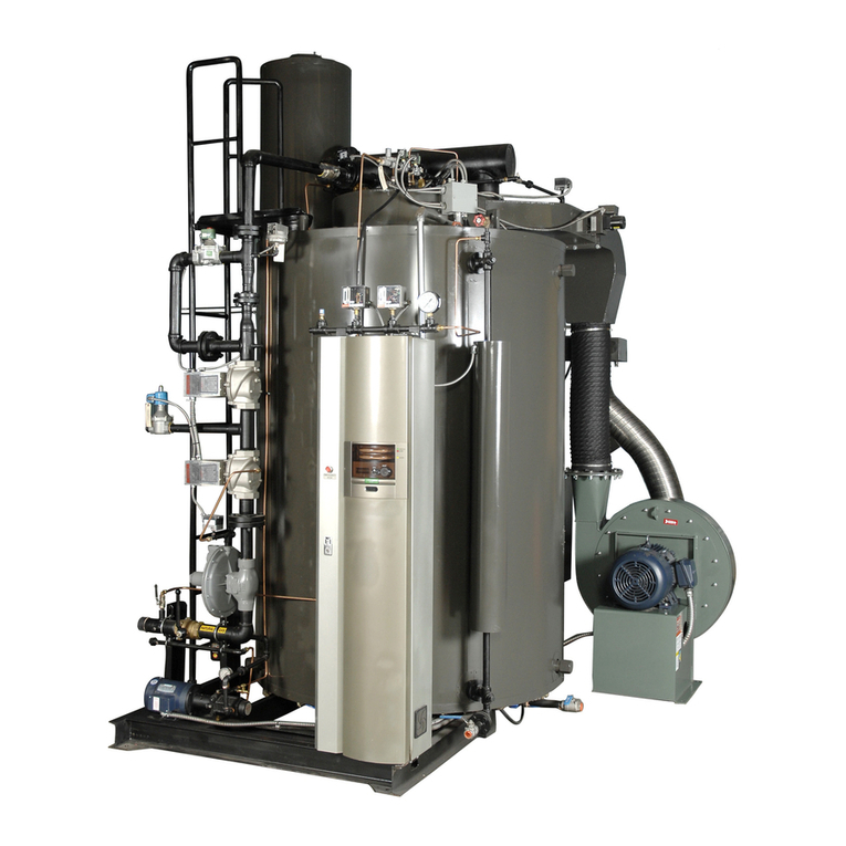
MIURA Steam Boiler presents to most inspectors in the field with an unfamiliar design. The purpose of this
section is to address common questions and to familiarize the inspector with a general overview of MIURA
boiler design and operational characteristics.
The MIURA boiler design comprises straight water tubes between upper and lower annular headers. Both
headers are encased in a castable refractory, leaving only the tubes exposed to combustion gases. There is
very little water and consequently very little energy stored within the steam boiler. Water remains exclusively
inside the tubes, with only incidental bubbling in the upper header. Therefore, the design features no natural
circulation such as the riser or downcomer effect common to natural circulation boilers.
Water is forced into the bottom header and tubes by means of a feed water pump. The water is flashed into
steam in the tubes, realizing a dynamic bubbling system that also cools the tubes. This bubbling action may
be best described as a “steam gradient,” with more steam at the top of the tubes than at the bottom. Steam
is accumulated in the upper header, with a final separation in the external separator. Condensate separated
in the external separator is fed back into the lower header.
As a result of this steam gradient characteristic, there are no strictly defined steam and water levels, and
thus, the boiler requires no sight glass. Furthermore, special modifications are incorporated into the boiler
construction and safety system in order to accommodate this.
First of all, two probes are placed directly into the top of the tubes. One probe is long, for low-water cutoff;
the other is short, for feed water control. This water volume control relies on electrical conductance, and the
bubbling action of the boiler water cools the tubes. As the volume of water in the steam boiler is consumed,
there is less bubbling at the top of the tubes, decreasing conductivity. Once the effective conductance
reaches a pre-determined level, the system triggers a ten-second delay before the feed water pump is turned
on. The pump continues to run until the bubbles re-establish effective contact with the probe. If the water
volume drops and loses an effective contact with the low-water cutoff probe, the boiler will shut down.
Secondly, probes are inserted into a water column (LVC) located on one side of the boiler. The water control
system relies on a more conventional, electrical conductance approach — specifically, when water contacts
a probe, a circuit is formed. Three probes control the boiler feed, with a short probe for high-fire, a medium
length probe for low-fire, and a long probe for low water cutoff. This safety configuration may seem confusing
to the inspector who encounters the MIURA Steam Boiler in the field for the first time, particularly because a
water column typically indicates a fixed water level. This is not true for Miura’s steam boilers, because of the
low water content and the fierce boiling action of the steam gradient. Control of this dynamic system has
been made possible by adding a special modification of the water column in order to create an artificial level.
The flanged pipe leading from the boiler body runs through the column, with three holes drilled in the pipe to
create an orifice effect. With this orifice effect, the artificial level oscillates — especially with the fluctuation of
the system load. This oscillation is desired and is directly proportional to the volume of water in the boiler
tubes.
Either of these feed water control systems can operate without the other for reliable feed water control.
However, the combination of these two systems provides double low-water safety and has thus been labeled
the Two-way Water Volume Control System.
Third in the list of safety modifications are thermocouples, attached directly to the tubes. These
thermocouples measure the temperature of the tubes and will shut down the boiler if a low water volume
condition is detected due to insufficient bubbling, if dry fire occurs. Boiler will caution by yellow sign if scale
buildup is detected. Scale formation reduces heat transfer rates and is therefore monitored directly based on
any increase in tube surface temperature. The early detection of scale formation is an important factor in
maintaining a high-efficiency boiler. According to the US National Bureau of Standards, 1/4" of scale buildup
on heating units requires up to 55% more energy to attain the same temperature.
The boiler will not operate should any of these low-water safeties fail. Only through tampering could the
boiler operate without these safeties and give rise to a dry fire condition. Even in the unlikely event that such


