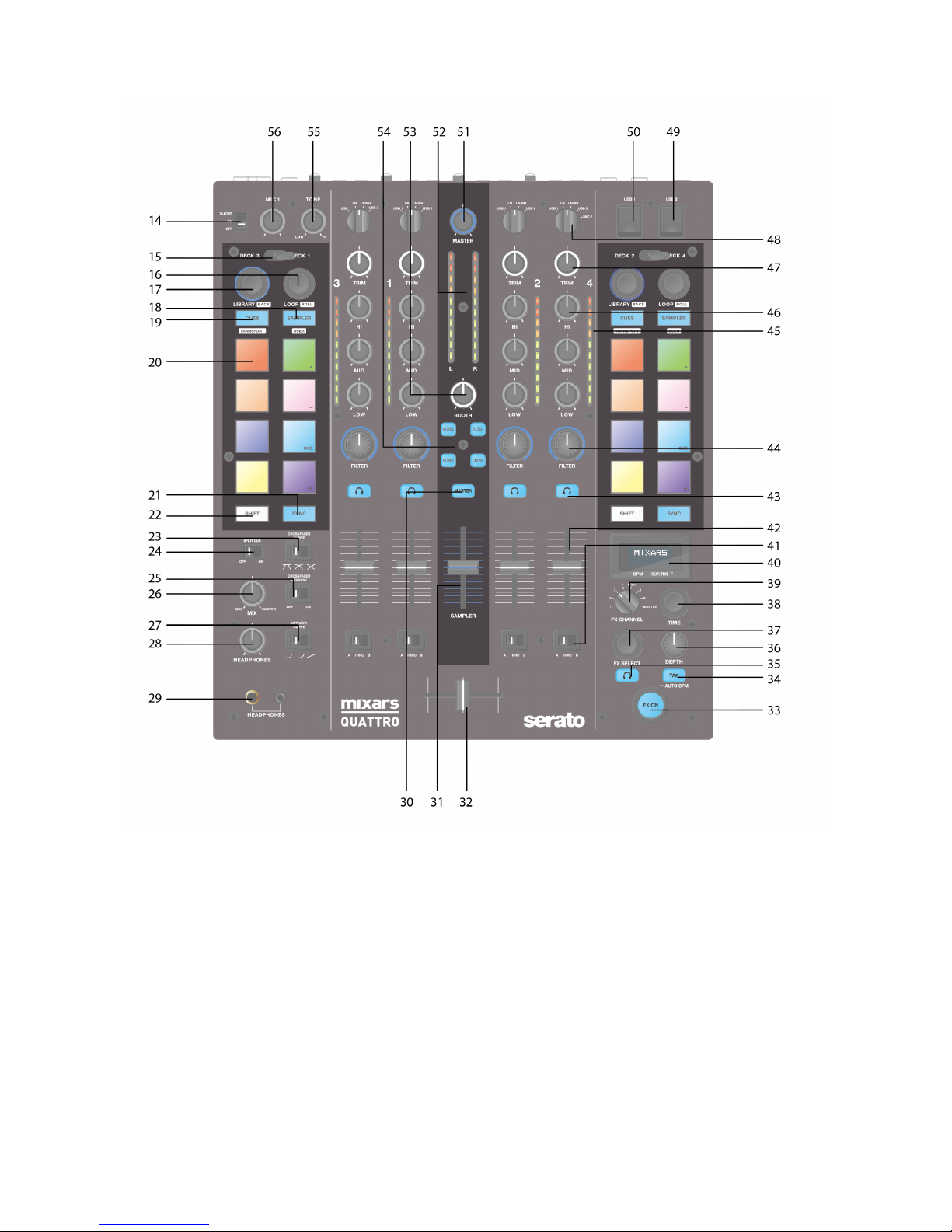
mixars QUATTRO User manual

User Manual (EN/ITA/FRA/ESP/DEU)
QUATTRO
Professional 4-Channel Club Mixer with dual Audio interface for Serato DJ
3
2
1 MASTER
B
A
MIC1
4
QUATTRO
FILTER
NOISE
CRUSH
MASTER
TAP
FX ON
ECHO
www.mixars.com

EN 1
Safety Instructions
1. Read these Instructions.
2. Keep these Instructions.
3. Heed all Warnings.
4. Follow all Instructions.
5. Do not use this apparatus near water.
6. Clean only with dry cloth.
7. Do not block any ventilation openings. Install in accordance with the manufacturer’s instructions.
8. Do not install near any heat sources such as radiators, heat registers, stoves, or other apparatus
(including amplifiers) that produce heat.
9. Do not defeat the safety purpose of the polarized plug. A polarized plug has two blades with one
winder than the other. The wide blade is provided for your safety. If the provided plug does not fit into
your outlet, consult an electrician for replacement of the obsolete outlet.
10. Protect the power cord from being walked on or pinched particularly at plugs, convenience
receptacles, and the point where they exit from the apparatus.
11. Only use attachments/accessories specified by the manufacturer.
12. Use only with the cart, stand, tripod, bracket, or table specified by the manufacturer,
or sold with the apparatus. When a cart is used, use caution when moving the cart/apparatus
combination to avoid injury from tip-over.
13. Unplug this apparatus during lightning storms or when unused for long periods of time.
14. Refer all servicing to qualified service personnel. Servicing is required when the apparatus has been
damaged in any way, such as power-supply cord or plug is damaged, liquid has been
spilled or objects have fallen into the apparatus, the apparatus has been exposed to rain or moisture,
does not operate normally, or has been dropped.
15. WARNING: To reduce the risk of fire or electric shock, do not expose this apparatus to rain or
moisture.
16. Since the appliance coupler is used as the disconnection device, the disconnect device shall remain
readily operable.
17. The ventilation should not be impeded by covering the ventilation openings with items, such as
newspapers, table-cloths, curtains, etc.
18. No naked flame sources, such as lighted candles, should be placed on the apparatus.
19. The apparatus should be used in moderate climate.
20. The apparatus shall not be exposed to dripping or splashing and that no objects filled with liquids,
such as vases, shall be placed on the apparatus.
The exclamation point within the equilateral triangle is intended to alert the user to the presence
of important operation and maintenance (servicing) instructions in the literature accompanying
this appliance.
The lightning flash with arrowhead symbol within the equilateral triangle is intended to alert the
use to the presence of un-insulated “dangerous voltage” within the product’s enclosure that may
be of sufficient magnitude to constitute a risk of electric shock.
WARNING
To reduce the risk of fire or electric shock, do not expose this apparatus to rain or moisture. The
apparatus shall not be exposed to dripping or splashing and that no objects filled with liquids,
such as vases, shall be placed on the apparatus.
CAUTION
To prevent electric shock, do not use this polarized plug with an extension cord, receptacle or other
outlet unless the blades can be fully inserted to prevent blade exposure.
CAUTION
To reduce the risk of electric shock, do not remove
any cover. No user-serviceable parts inside.
Refer servicing to qualified service personnel only.

A. Accessories and Driver Installation
Check for the following parts included in the package with the main unit:
Hardware guide x 1
USB Cable x 1
AC cord x 1
Driver installation
Mac
No driver needed
Windows
Download the driver via our website: www.mixars.com
Double click on the .exe file to start installation and follow the on-screen instructions.
Please note that you may have to reconnect Quattro after installation.
The Mixars Quattro is a class-compliant device for Mac OS X however will require drivers for Windows.
Please make sure you have completed driver installation before use with Serato DJ.
EN 2

B. Controls and functions
Rear
1. Power On/Off switch
Turns the power of the unit On and Off.
2. AC In
Connect the power cord here.
3. FX Return input, TRS
FX Return input for onboard FX.
4. FX Send output, TRS
FX Send output for the onboard FX.
5. Output Level Trim knob
Adjust the output level from 0dB to -6dB.
6. Secondary Master output, RCA
Secondary RCA Master output (Unbal.), controlled via the «Master» knob
7. Record output
Additional RCA Record output (Unbal.)
8. Secondary Line inputs
Line signal dedicated secondary input for each channel.
9. Main Phono/Line inputs (Serato Inputs)
Main Phono / Line Inputs for each channel.
Use the dedicated «Phono / Line» button nearby
for selecting the right setting depending on the equipment used (Phono or Line sources).
Use this inputs for Serato timecode Vinyls/ CDs in order to use with Serato DJ.
10. Master output, Balanced XLR
Main Balanced XLR output, controlled via the «Master» knob
11. Secondary Mic input
TRS Microphone input, controlled via the «MIC/AUX» knob.
12. Booth Output, TRS
Secondary TRS output (Bal.), controlled via the «Booth» knob
13. Mic input
XLR / TRS Combo Microphone input, controlled via the «MIC/AUX» knob
EN 3

Top
14. Mic Talkover/ On/ Off switch
Switch the Mic 1 to Talkover, On or off mode.
15. Deck select lever switch
Select the destination deck [Deck 3/1 and Deck 2/4] for the corresponding MIDI control area [Left/
Right].
16. Loop / Loop roll
Control the loop and loop roll function in Serato DJ by turning and pressing the knob. Press and
hold the «SHIFT» button (see 22) for controlling the loop roll function.
17. Library, Load controls
Library:
Scroll the Library by turning the knob and display the next level or load the selected song by pressing it.
Hold «Shift» and press for turning to the previous level.
18. Sampler Button
Switch the performance pads to Sampler Mode. Hold «Shift» and press to switch to User Mode.
19. CUES Button
Switch the performance pads to CUES Mode. Hold «Shift» and press to switch to Transport Mode.
20. Performance Pads
Use to trigger cue points, samples, transport control or other user defined functions in Serato DJ.
EN 4

21. Sync Button
Syncronize a track to another by pressing the corresponding «Sync» button and turn off the function by
pressing «Sync» while holding «Shift».
22. Shift button
Hold for enabling the shifted functions of some controls
23. Crossfader Fader Curve switch
Switch among the 3 cross fader settings Hard (towards left) to Soft (towards right) for different
application.
24. Split Cue On/Off switch
If enabled, the headphones signal gets split: Master signal on one channel, and the enabled Cue signals
selected via the «CUE» buttons (see 43), on the other channel.
25. Crossfader Reverse switch
Reverses the Left with the Right Channel on the crossfader.
26. CUE Mix
Turn for adjusting between Cue and Master signal on the headphone output.
27. Upfader Fader Curve switch
Switch among the 3 cross fader settings Hard (towards left) to Soft (towards right) for different
application.
28. Headphones Level
Adjust the headphones volume.
29. Headphones Output connector
6.35mm and 3.5mm jack for connecting headphones
30. Master On CUE switch
Press to enable the Master on CUE headphone channel.
31. Sampler Volume
Control sampler volume level in Serato DJ
32. Crossfader
Crossfade between the Left and Right channels of audio assigned to them by the « Channel assignment
switch» (see 41)
33. FX ON switch
Enable/ disable the FX proceeded signal to the master output.
34. TAP button
Tap to enter manual BPM to the FX unit. Press and hold for 3 sec to enable auto BPM detection.
35. FX CUE switch
Enable/ disable the FX proceeded signal to the headphone cue output.
36. FX Depth parameter knob
Adjust the FX depth or dry/wet of the selected FX.
37. FX Select encoder
Turn to select different FX and press to select.
38. FX Time parameter knob
Adjust the FX time/ beat parameter of the selected FX. Press to switch between Time and Beat
parameter.
39. FX on Channel selector
Select the desired channel to apply the FX.
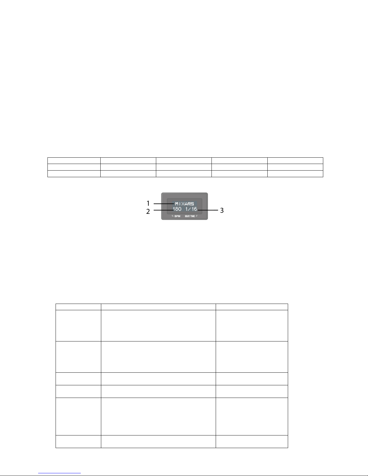
40. Onboard FX display
Display various information about the FX
41. Channel assignment switch
Assign the corresponding channel to the left or right channel of the corssfader. When “THRU” is selected,
the channel signal will go through to master directly bypassing the crossfader.
42. Channel faders
Adjust the volume level of the corresponding channel.
43. Cue On/Off
Assign the corresponding channel to the Cue signal.
44. Channel Sound Texture FX knob (FILTER)
Adjust the parameter/ level of the selected sound texture FX.
45. Channel level meter
Display the corresponding channel level signal
46. Channel EQ
Adjust the equalizer settings for the corresponding channel
47. Channel Trim
Adjust the overall level for the corresponding channel.
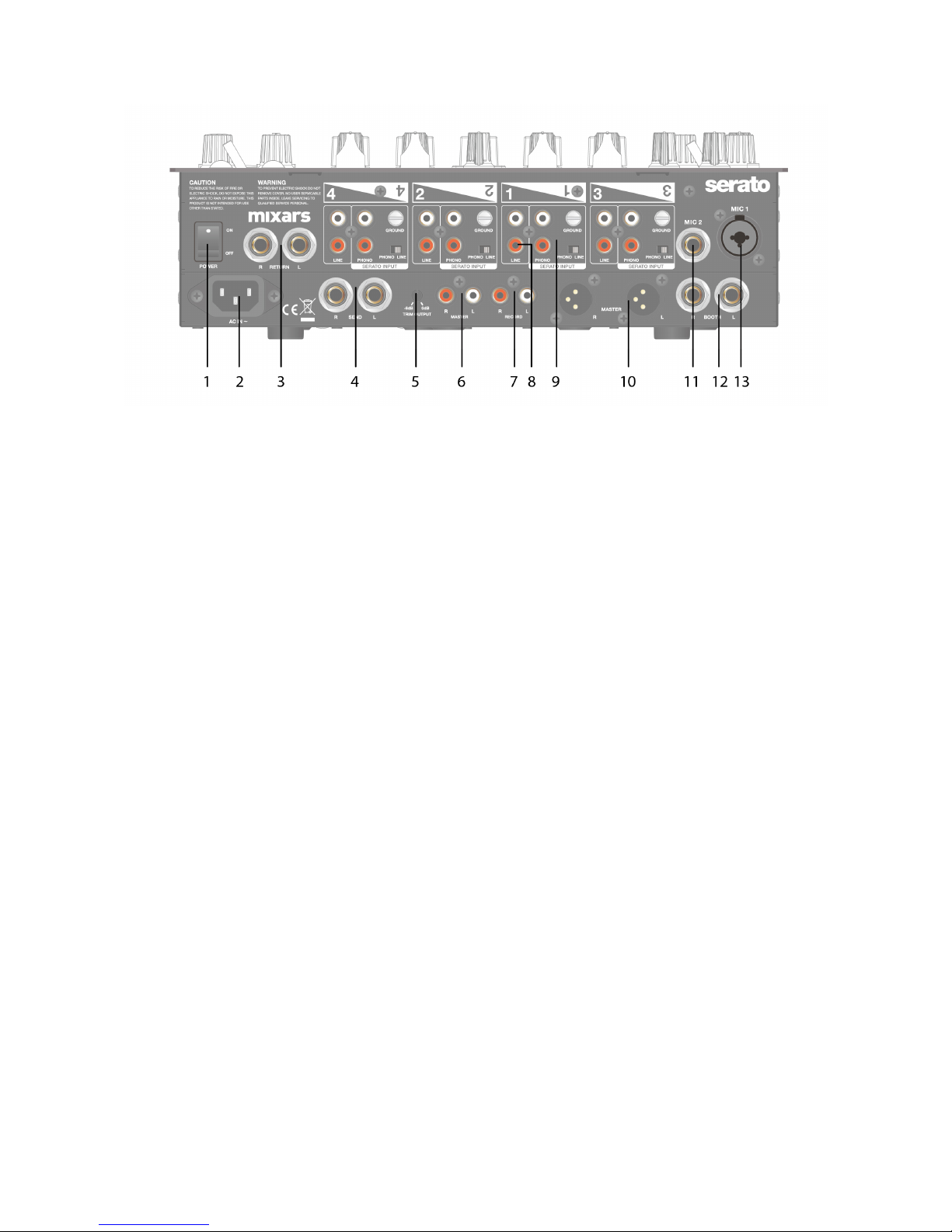
48. Source Switch
Select the input to be controlled on the corresponding channel.
Switch between Phono/Line (see 9), Line (see 8), Serato – USB1 (see 50) or Serato – USB2 (see 49).
For Deck 4, there is an extra input source of MIC 2.
49. USB 2 connector
Connect the mixer to your computer using the included USB cable for using it with Serato DJ. To use this
USB device, use the «Source Switch» (see 48) to select to USB2
50. USB 1 connector
EN 5

Connect the mixer to your computer using the included USB cable for using it with Serato DJ. To use this
USB device, use the «Source Switch» (see 48) to select to USB1
51. Master volume
Adjust the volume of the master level signal.
52. Master Level Meter
Display the Master Level Signal.
53. Booth
Adjust the level of the «Booth» output.
54. Sound Texture FX selection switch.
Switch between Filter, Noise, Crush and Echo effect and control the FX parameter by «Channel Sound
Texture FX knob» (see 44)
55. Mic 1 tone control
Control the tone of the mic 1.
56. Mic 1 level control
Control the level of the mic 1.
C. On board FX Controls and functions
The Quattro provides a BPM synced FX unit for adding special effects to the performance. There are 15
different FX selections:
Filter
Flanger
Delay
Echo
Reverb
Transformer
Pitch
Loop Roll
Reverse Roll
Noise
Bit Crusher
Gate
Tape Delay
Vinyl Brake
Send/return
The Display of the Quattro shows various info about the FX:
1. The FX Name
The current selected FX is shown. Turn the FX select Encoder to change to a different FX, the new
FX name will be flashing. Press the encoder to select the FX and the display name will stop
flashing.
2. BPM
The current BPM is shown. Tap the TAP button to enter a manual BPM. Press and hold the TAP
button for 3 seconds to enable Auto BPM, the display will show “AUTO BPM” for 2 seconds.
3. Beat/ Time parameter
The current Beat/ Time parameter is shown. Press the TIME encoder to switch the selection
between Beat and Time parameter.
For different FX, the TIME and DEPTH knobs control different parameters:
Effect
Time Control Function
Depth Control Function
Filter
Beat range: 1/4 to 64/1
Time Range: 10ms to 32000ms (when
over 9999ms, “a.bs” format will be used
in normal display. E.g. “32.0s” for
32000ms)
Depth (Dry/Wet) 0-100%
Flanger
Beat range: 1/4 to 64/1
Time Range: 10ms to 32000ms (when
over 9999ms, “a.bs” format will be used
in normal display. E.g. “32.0s” for
32000ms)
Depth (Dry/Wet) 0-100%
Delay
Beat range: 1/8 to 16/1
Time Range: 1ms to 4000ms
Depth (Dry/Wet) 0-100%
Echo
Beat range: 1/8 to 16/1
Time Range: 1ms to 4000ms
Depth (Dry/Wet) 0-100%
Reverb
Non BPM synced. Just adjust the extend
(room size) of reverb from 0% to 100%.
Display on normal display should show
“0%” to “100%”.
“Size” should be shown on display as title
when turning the time knob.
Depth (Dry/Wet) 0-100%
Transformer
Beat range: 1/16 to 16/1
Time Range: 10ms to 16000ms (when
Depth (Dry/Wet) 0-100%
EN 6

over 9999ms, “a.bs” format will be used
in normal display. E.g. “16.0s” for
16000ms)
Pitch
Non BPM synced. Pitch range from -50%
to 100%. “PITCH” is shown as title when
adjusting this parameter.
Fixed 100% Wet
Loop Roll
Beat range: 1/16 to 16/1
Time Range: 10ms to 4000ms
Fixed 100% Wet
Reverse Roll
Beat range: 1/16 to 16/1
Time Range: 10ms to 4000ms
Fixed 100% Wet
Noise
Beat range: 1/4 to 64/1
Time Range: 10ms to 32000ms (when
over 9999ms, “a.bs” format will be used
in normal display. E.g. “32.0s” for
32000ms)
Depth (Dry/Wet) 0-100%
Bit Crusher
Non BPM synced. Quality parameter
range from -100% to 100%. “QUALITY” is
shown on title when adjusting this
parameter
Depth (Dry/Wet) 0-100%
Gate
Non BPM synced. Threshold adjustment of
steps:
From 0% to 100%
Depth (Dry/Wet) 0-100%
Tape Delay
Non BPM synced. Tone pitch of the delay
signal form -100% to 100%.
Depth (Dry/Wet) 0-100%
Vinyl Brake
Non BPM synced. Break time from 10ms
to 4000ms.
Manual control of the
Break FX.
Turn clockwise to engage
and shorten the break
time.
Turn anti-clockwise to re-
engage the break FX with
a longer break time.
Send/return
NA. Display “---“ for the time/ beat field
Depth (Dry/Wet) 0-100%
EN 7

D. Audio Routing
There are 2 audio routing settings in Quattro, namely the Serato routing and non-Serato routing.
In Serato mode routing, the Quattro acts as a controller and most of the mixing is done in Serato DJ
software. It allows post-crossfader FX from Serato DJ.
The Serato mode audio routing:
EN 8

In non-Serato mode routing, the Quattro works as a typical external hardware mixer that the mixing is
done by Quattro hardware.
The non-Serato mode Audio routing:
There are different ways to switch between the 2 audio routings:
1. When Serato DJ software is open and initiated, it will trigger the connected Quattro to change to
Serato mode routing automatically.
2. Press and hold the MASTER button and power on the Quattro. Audio routing mode and be
selected and changed by using the FX Select encoder and the current selected mode is shown on
the Display. Turn the FX Select encoder to select desired audio routing and press to confirm and
finish the power on.
3. When the Quattro is powered on and in use, press and hold the 2 SHIFT buttons for 5 seconds, a
system utility menu will be shown on the display. Use the FX Selector Encoder to select to the
Audio routing section and select desired audio routing.
The audio interface is a 10-in 12-out interface with assignment:
CH
Inputs
Outputs
1
Deck 1 in L (DVS)
Deck 1 out L
2
Deck 1 in R (DVS)
Deck 1 out R
3
Deck 2 in L (DVS)
Deck 2 out L
4
Deck 2 in R (DVS)
Deck 2 out R
5
Deck 3 in L (DVS)
Deck 3 out L
6
Deck 3 in R (DVS)
Deck 3 out R
7
Deck 4 in L (DVS)
Deck 4 out L
8
Deck 4 in R (DVS)
Deck 4 out R
9
Record in L
CUE out L
10
Record in R
CUE out R
11
NA
Sampler out L
12
NA
Sampler out R
13
NA
NA
14
NA
NA
15
NA
NA
16
NA
NA
EN 9

E. System Utility Menu
To enter System Utility Menu, press and hold the 2 SHIFT buttons when the Quattro is working. The
menu will be shown on the Display. Use the FX Select Encoder to browse to different option and
press the encoder to select and change the settings:
1. Audio routing
Select between Serato and non-Serato Audio routing
2. Crossfader power
Select between the linear and power crossfader setting. This will also update the selection in
connected Serato DJ software on both USB 1 and USB 2 connection.
3. Firmware Version
Display the firmware version.
4.Exit system utility menu
Press the FX Select Encoder to exit system utility menu.
F. Firmware Update
Mixars will continue improve the product and fix bugs by releasing new firmware for the production.
New firmware and firmware update software tool can be downloaded from Mixars website
(http://www.mixars.com). Firmware update procedure:
1. Download the firmware update tool and latest firmware from Mixars website.
2. Connect the USB able to the computer.
3. Press and hold the FX CUE and TAP button and power on. “FIRMWARE UPDATE” will be shown on
the display and the Quattro is in Firmware update mode.
4. Open the firmware update software and locate the firmware update file.
5. Follow the on-screen instruction to start firmware update and wait for the prompt for update
finish
6. Power cycle the Quattro after firmware update.
G. Specifications
1. GENERAL SECTION
Power Supply AC 100~240V 50Hz/60Hz
Dimensions 320(W) x 362(D) x 107(H) mm
Consumption 20W
Weight 5.35Kg
2. STANDARD TEST CONDITION
Ambient Temperature 23 +/- 2 degC
Relative Humidity 65% +/- 5%
NOTE: Measurements can be carried out between 5 degC to 35 degC and 45% to 85% relative
humidity.
3. INPUT/OUTPUT IMPEDANCE & SENSITIVITY: (1KHz,EQ FLAT, MAX. GAIN )
3-1. INPUT IMPEDANCE AND REFERENCE INPUT LEVEL:
LINE: 47KΩ/-14dBV (200mV)
PHONO: 47KΩ/-50dBV (3.16mV)
MIC : 5KΩ/-54dBV (2mV)
RETURN: 47KΩ/-20dBV (100mV)
USB -12dBFS
3-2. OUTPUT IMPEDANCE AND REFERENCE OUT LEVEL:
MASTER(XLR): 600 OHM / 0dBV (1V) ± 2dB (Signal to Signal 600 ohm)
BOOTH: 600 OHM / 0dBV (1V) ± 2dB (Signal to Signal 600 ohm)
MASTER(RCA): 1K OHM / 0dBV (1V) ± 1dB (load=100K ohm)
RECORD: 1K OHM / -9dBV (355mV) ± 1dB (load=100K ohm)
SEND: 1K OHM / -14dBV (200mV) ± 1dB (load=100K ohm)
PHONE: 32 OHM / -3dBV (708mV) ± 1dB (load=32 ohm)
EN 10

4. MAXIMUM GAIN: ( EQ FLAT, REFERENCE INPUT LEVEL , MAX. GAIN)
MASTER (XLR)BOOTH OUTPUT:
LINE : +14dB (AT 600Ω) ± 1dB
PHONO : +50dB (AT 600Ω) ± 2dB
MIC : +54dB (AT 600Ω) ± 2dB
RETURN: +20dB (AT 600Ω) ± 1dB
MASTER(RCA) OUTPUT:
LINE : +14dB (AT 100KΩ) ± 1dB
PHONO : +50dB (AT 100KΩ) ± 2dB
MIC : +54dB (AT 100KΩ) ± 2dB
RETURN: +20dB (AT 600Ω) ± 1dB
RECORD OUTPUT:
LINE : +5dB (AT 100KΩ) ± 1dB
PHONO : +41dB (AT 100KΩ) ± 2dB
MIC : +45dB (AT 100KΩ) ± 2dB
RETURN: +11dB (AT 600Ω) ± 1dB
SEND OUTPUT:
LINE : +0dB (AT 100KΩ) ± 1dB
PHONO : +36dB (AT 100KΩ) ± 2dB
MIC : +40dB (AT 100KΩ) ± 2dB
5. MAXIMUM INPUT: ( EQ FLAT,MIC,TRIM,MASTER AT 9 O’CLOCK, ADJUST INPUT 1KHz LEVEL
TO OUTPUT LEVEL LESS THAN 1% T.H.D WITH A-w/20KHz LPF )
LINE: MORE THAN +15dBV THD<1%
RETURN: MORE THAN +9dBV THD<1%
PHONO: MORE THAN -21dBV THD<1%
MIC: MORE THAN -25dBV THD<1%
6. MAXIMUM OUTPUT: (LINE INPUT, EQ FLAT,MIC,TRIM,MASTER AT MAX, ADJUST INPUT
1KHz LEVEL TO OUTPUT LEVEL LESS THAN 1% WITH A-w/20kHz LPF)
MASTER(XLR): MORE THAN +17dBV LOAD=600ΩTHD<1%
BOOTH: MORE THAN +17dBV LOAD=600ΩTHD<1%
MASTER(RCA): MORE THAN +17dBV LOAD=100KΩTHD<1%
RECORD: MORE THAN +8 dBV LOAD=100KΩTHD<1%
SEND: MORE THAN +3dBV LOAD=100KΩTHD<1%
PHONE: MORE THAN +4dBV LOAD=32ΩTHD<1%
7. FREQUENCY RESPONSE: (EQ FLAT, PHONO AT -60dB/OTHER REFERENCE INPUT LEVEL ,
MIC,TRIM,MASTER AT MAX.)
LINE: 20 - 20KHz +2/-3dB
MIC: 20 - 20KHz +2/-3dB
PHONO: 20 - 20KHz +2/-3dB
USB: 20 - 20KHz (48K/24b-1KHz20Hz20KHz.WAV) +2/-3dB
8. THD + N: (1KHz INPUT ,MIC TRIM & MASTER AT 12 O’CLOCK , WITH A-w./20KHz LPF)
LINE0.01 % AT 0dB INPUT
RETURN0.01 % AT 0dB INPUT
PHONO0.02 % AT -36dB INPUT
MIC0.03 % AT -40dB INPUT
9. S/N RATIO: ( 1KHz INPUT , MIC/AUX, TRIM, MASTER AT 12 O’CLOCK, WITH A-w/20KHz
LPF, INPUT SHORT WHEN NO SIGNAL)
LINE81dB AT 0dB INPUT
RETURN81dB AT 0dB INPUT
PHONO81dB AT -36dB INPUT
MIC74dB AT -40dB INPUT
10. CROSSTALK: (1KHz INPUT , MIC/AUX, TRIM, MASTER AT 12 O’CLOCK WITH A-w/ 20KHz
LPF, INPUT SHORT WHEN NO SIGNAL )
LINE: MORE THAN 81dB @ EACH CHANNEL INPUT AT 0dB INPUT
PHONO: MORE THAN 81dB @ EACH CHANNEL INPUT AT -36dB INPUT
11. L&R CHANNEL SEPARATION: (1KHz INPUT , MIC/AUX, TRIM, MASTER AT 12 O’CLOCK WITH
A-w/20KHz LPF, INPUT SHORT WHEN NO SIGNAL)
LINE: MORE THAN 81dB @BETWEEN L AND R CHANNEL AT 0dB INPUT
PHONO: MORE THAN 81dB @BETWEEN L AND R CHANNEL AT -36dB INPUT
EN 11

12. EQUALIZER RESPONSE: (REFERENCE INPUT LEVEL , MIC/AUX, TRIM MASTER AT MAX.
WITH 20KHz LPF)
LINE:
(1) Low Band: (Low Band center frequency is 70Hz )
Maximum level: +12 ± 1dB (at 70Hz)
Minimum level: -25 ± 1dB (at 70Hz)
(2) Middle Band: (Middle Band center frequency is 1KHz )
Maximum level: +12 ± 1dB (at 1KHz)
Minimum level: -25 ± 1dB (at 1KHz)
(3) High Band: (Hi Band center frequency is 13KHz )
Maximum level: +12 ± 1dB (at 13KHz)
Minimum level: -25 ± 1dB (at 13KHz)
MIC
Hi: -28dB ± 2dB AT 100Hz
Low: -28dB ± 2dB AT 10KHz
13. Fader Kill: (0dB 1KHz INPUT LEVEL , TRIM/MASTER AT 12 O’CLOCK. MIC SW OFF WITH A-
w/ 20KHz LPF )
Channel Fader: MORE THAN 91dB AT 1KHz
Cross Fader: MORE THAN 91dB AT 1KHz
14. LEVEL DIFFERENCE L&R: (1KHz REFERENCE INPUT LEVEL , TRIM, MASTER AT MAX. WITH A-
w/20KHz LPF)
LINE: ±1dB
PHONO: ±1.5dB
15. NOTES
(1) The specifications are subject to change to any improvement by negotiations in advance.
(2) The parts are subject to change to any improvement within the range of the specifications.
EN 12

ITA 1
Istruzioni di sicurezza
1. Leggere queste istruzioni.
2. Conservare queste istruzioni.
3. Prestare attenzione a tutte le avvertenza.
4. Seguire tutte le istruzioni.
5. Non utilizzare quest’apparecchiatura in prossimità di acqua.
6. Pulire solo con un panno asciutto.
7. Non ostruire le aperture di ventilazione. Eseguire l’installazione secondo le istruzioni del costruttore.
8. Non effettuare l’installazione in prossimità di fonti di calore come radiatori, regolatori di calore, stufe o
altre apparecchiature (compresi gli amplificatori) che producono calore.
9. Non inibire la funzione di sicurezza della spina polarizzata. La spina polarizzata ha due piedini, uno più
largo dell’altro. Il piedino più largo ha una funzione di sicurezza. Qualora la spina fornita non si inserisse
nella vostra presa, consultare un tecnico per la sostituzione della presa.
10. Assicurarsi che il cavo di alimentazione non possa essere calpestato o schiacciato, in particolare in
prossimità delle spine, delle
prese a muro e nei punti in cui esce dall’apparecchio.
11. Utilizzare solamente accessori specificati dal costruttore.
12. Utilizzare solamente con il carrello, il cavalletto, il treppiedi, la staffa o il piano specificati
dal costruttore oppure forniti insieme all’apparecchio. Quando si utilizza un carrello, prestare
attenzione nella movimentazione del gruppo carrello/apparecchio per evitare lesioni
provocate dal ribaltamento del gruppo stesso.
13. Scollegare questo apparecchio in caso di tempeste di fulmini oppure di inutilizzo prolungato.
14. Affidare tutte le operazioni di manutenzione a personale qualificato. Gli interventi di manutenzione
sono necessari quando l’apparecchio viene danneggiato in qualunque modo, ad esempio in caso di danni
al cavo di alimentazione o alla spina, di fuoriuscita di liquido
o di caduta di oggetti all’interno dell’apparecchio stesso, o ancora qualora l’apparecchio, dopo esser stato
esposto a pioggia o umidità, non funzioni correttamente o qualora sia caduto.
15. AVVERTENZA: Per ridurre il rischio di incendio o di folgorazione, non esporre l’apparecchiatura alla
pioggia o all’umidità.
16. Poiché l’accoppiatore dell’apparecchio viene utilizzato come sezionatore, esso deve essere sempre
prontamente azionabile.
17. Non ostacolare la ventilazione coprendo le relative aperture con oggetti, giornali, tovaglie, tende o
altro.
18. Evitare di posizionare sull’apparecchiatura fonti di fiamme libere, come ad esempio candele accese.
19. L’apparecchiatura è progettata per essere utilizzata in ambienti con clima temperato.
20. L’apparecchiatura non deve essere esposta a gocciolamento o schizzi e pertanto nessun oggetto
contenente liquidi, come ad esempio vasi, dovrà essere posizionato sulla stessa.
Il punto esclamativo all’interno del triangolo ha lo scopo di attirare l’attenzione dell’utente sulla
presenza di istruzioni di funzionamento e di manutenzione (assistenza) importanti riportate nella
documentazione fornita insieme all’apparecchiatura.
Il simbolo del lampo all’interno del triangolo ha lo scopo di attirare l’attenzione dell’utente sulla
presenza di “tensione pericolosa” non isolata nei ripari del prodotto, che potrebbe avere una
potenza sufficiente a costituire un rischio di scossa elettrica.
AVVERTENZA
Per ridurre il rischio di incendio o di folgorazione, non esporre l’apparecchiatura alla pioggia o all’umidità.
L’apparecchiatura non deve essere esposta a gocciolamento o schizzi e pertanto nessun oggetto
contenente liquidi, come ad esempio vasi, dovrà essere posizionato sulla stessa.
ATTENZIONE
Per prevenire le scosse elettriche non utilizzare questa spina polarizzata con una prolunga, una presa a
muro o altre prese a meno che i piedini non possano essere inseriti completamente così da evitare
l’esposizione degli stessi.
ATTENZIONE
Per ridurre il rischio di scosse elettriche non rimuovere i
pannelli di copertura. Non sono p resenti all’interno com p onenti
che preve dono u na manute nzione da parte del l ’ute nte.
Affidare le operazioni di manutenzione solamente a
personale qualificato.

ITA 2
A. Accessori e installazione dei driver
Verificare che i componenti riportati di seguito siano contenuti
nell’imballaggio dell’unità principale:
guida hardware x 1
cavo USB x 1
cavo CA x 1
Installazione dei driver
Mac
Non è necessario alcun driver
Windows
Scaricare il driver dal nostro sito: www.mixars.com
Fare doppio click sul file .exe per avviare l’installazione e seguire le istruzioni a video.
Potrebbe essere necessario ricollegare Quattro dopo l’installazione.
Mixars Quattro è un dispositivo compatibile con Mac OS X; tuttavia richiede alcuni driver per Windows.
Accertarsi di aver completato l’installazione dei driver prima dell’utilizzo con Serato DJ.

B. Comandi e funzioni
Lato posteriore
1. Interruttore di accensione/spegnimento
Consente di attivare e disattivare l’alimentazione dell’unità.
2. Ingresso CA
Collegare qui il cavo di alimentazione.
3. Ingresso ritorno FX, TRS
Ingresso di ritorno FX per l’FX a bordo.
4. Uscita invio FX, TRS
Uscita invio FX per l’FX a bordo.
5. Pomello di regolazione livello uscita
Regolazione del livello di uscita da 0dB a -6dB.
6. Uscita master secondaria, RCA
Uscita master RCA secondaria (sbil.), comandata tramite il pomello «Master»
7. Uscita registrazione
Uscita di registrazione RCA supplementare (sbil.)
8. Ingressi linea secondari
Ingresso secondario dedicato al segnale di linea per ogni canale.
9. Ingressi phono/linea principali (ingressi Serato)
Ingressi phono/linea principali per ogni canale.
Utilizzare il pulsante dedicato “phono/linea” a lato
per selezionare la corretta impostazione in base all’apparecchiatura utilizzata (fonti phono o di linea).
Utilizzare questi ingressi per vinili/CD timecode di Serato per utilizzare Serato DJ.
10. Uscita master, XLR bilanciato
Uscita XLR principale bilanciata, comandata tramite il pomello “Master”
11. Ingresso Mic secondario
Ingresso microfono TRS, comandato tramite pomello “MIC/AUX”.
12. Uscita cabina, TRS
Uscita TRS secondaria (bil.), comandata tramite il pomello “Cabina”
13. Ingresso Mic
Ingresso microfono combinato XLR/TRS, comandato tramite pomello “MIC/AUX”
ITA 3

Parte superiore
14. Interruttore accensione/spegnimento/talkover
Commuta il Mic 1 in funzione Talkover o in modalità On o off.
15. Interruttore a leva di selezione deck
Consente di selezionare il deck di destinazione [deck 3/1 e deck 2/4] per l’area di controllo MIDI
corrispondente [sinistra/destra].
16. Loop / Loop roll
Consente di controllare il loop e la funzione di loop roll nel Serato DJ ruotando e premendo il pomello.
Premere e
tenere premuto il tasto «SHIFT» (vedi 22) per controllare la funzione loop roll.
17. Comandi libreria, caricamento
Libreria:
consente di scorrere la libreria ruotando il pomello, visualizzare il livello successivo oppure caricare il
brano selezionato premendolo. Mantenere premuto il tasto «Shift» e premere per ritornare al livello
precedente.
18. Pulsante campionatore
Commuta i performance pad nella modalità Campionatore. Mantenere premuto il tasto «Shift» e premere
per passare alla Modalità Utente.
19. Pulsante CUES
Consente di commutare i performance pad alla modalità CUES. Mantenere premuto il tasto «Shift» e
premere per passare alla Modalità Trasporto.
ITA 4

20. Performance pad
Da utilizzare per attivare punti cue, campioni, comando di trasporto o altre funzioni definite dall’utente in
Serato DJ.
21. Pulsante Sync
Consente di sincronizzare una traccia con un’altra premendo il rispettivo pulsante”Sync” e di spegnere la
funzione premendo “Sync” e mantenendo premuto “Shift”.
22. Tasto Shift
Mantenere premuto il tasto Shift per abilitare le funzioni “shiftate” degli stessi comandi
23. Interruttore curva Fader Crossfader
Consente di passare da una delle 3 impostazioni di crossfader da Hard (verso sinistra) a Soft (verso
destra) disponibili per diverse applicazioni.
24. Interruttore accensione/spegnimento split cue
Se abilitato, il segnale delle cuffie viene suddiviso: segnale master su un canale e segnali Cue abilitati
tramite i pulsanti “CUE” (vedi 43) sull’altro canale.
25. Interruttore inversione crossfader
Consente di invertire il canale sinistro con il destro sul crossfader.
26. CUE Mix
Ruotarlo per regolare il segnale Cue e Master sull’uscita delle cuffie.
27. Interruttore curva Fader Upfader
Consente di passare da una delle 3 impostazioni di crossfader da Hard (verso sinistra) a Soft (verso
destra) disponibili per diverse applicazioni.
28. Livello cuffie
Regolare il volume delle cuffie.
29. Connettore uscita cuffie
jack da 6,35mm e 3,5mm per il collegamento delle cuffie
30. Interruttore Master su CUE
Premerlo per abilitare il Master sul canale CUE delle cuffie.
31. Volume campionatore
Consente di controllare il volume del campionatore in Serato DJ
32. Crossfader
Crossfade tra i canali audio sinistro e destro ad essi assegnati dall’interruttore di “assegnazione canale”
(vedi 41)
33. Interruttore FX ON
Consente di abilitare/disabilitare il segnale FX verso l’uscita master.
34. Pulsante TAP
Premere questo pulsante per inserire manualmente un valore di BPM nell’unità FX. Premere e mantenere
premuto per 3 secondi per abilitare il rilevamento automatico del BPM.
35. Interruttore FX CUE
Consente di abilitare/disabilitare il segnale FX verso l’uscita cue delle cuffie.
36. Pomello parametro profondità FX
Consente di regolare la profondità FX o dry/wet dell’FX selezionato.
37. Encoder selezione FX
Ruotarlo per selezionare un FX diverso e premere per selezionarlo.
38. Pomello parametro tempo FX
Consente di regolare il parametro di beat/tempo dell’FX selezionato. Premerlo per passare dal parametro
Tempo al parametro Beat.
39. Selettore canale FX
Consente di selezionare il canale desiderato da applicare all’FX.
40. Display FX di bordo
Visualizza varie informazioni sull’FX
41. Interruttore di assegnazione canale
Consente di assegnare il canale corrispondente al canale sinistro o destro del crossfader. Quando si
seleziona “THRU”, il segnale del canale passerà attraverso il master bypassando direttamente il
crossfader.
42. Fader canali
Consente di regolare il livello del volume del canale corrispondente.
43. Cue On/Off
Consente di assegnare il canale corrispondente al segnale Cue.
44. Pomello FX texture del suono del canale (FILTRO)
Consente di regolare il parametro/livello dell’FX texture suono selezionata.
45. Misuratore livello canale
Visualizza il segnale del livello del canale corrispondente
46. Equalizzatore canale
Consente di regolare le impostazioni dell'equalizzatore per il canale corrispondente
47. Regolazione canale
Consente di regolare il livello generale del canale corrispondente.
48. Interruttore fonte
Consente di selezionare l’ingresso da controllare sul canale corrispondente.
Consente di passare da Phono/linea (vedi 9), linea (vedi 8), Serato – USB1 (vedi 50) o Serato – USB2
ITA 5

(vedi 49). Per il deck 4 è presente una fonte ingresso supplementare del MIC 2.
49. Connettore USB 2
Consente di collegare il mixer al vostro computer utilizzando il cavo USB fornito in dotazione per utilizzare
il mixer con Serato DJ. Per utilizzare questo dispositivo USB, agire sull’interruttore “Fonte” (vedi 48) per
selezionare l’USB2
50. Connettore USB 1
Consente di collegare il mixer al vostro computer utilizzando il cavo USB fornito in dotazione per utilizzare
il mixer con Serato DJ. Per utilizzare questo dispositivo USB, agire sull’interruttore “Fonte” (vedi 48) per
selezionare l’USB1
51. Volume master
Regolare il volume del segnale di livello master.
52. Misuratore livello master
Visualizza il segnale del livello master.
53. Cabina
Consente di regolare il livello dell’uscita “Cabina”.
54. Interruttore di selezione FX texture del suono.
Consente di impostare filtro, disturbo, effetto Crush ed Eco e di controllare il parametro FX tramite il
pomello “FX texture del suono del canale” (vedi 44)
55. Comando tono Mic 1
Consente di controllare il tono del microfono 1.
56. Comando livello Mic 1
Consente di controllare il livello del microfono 1.
C. Comandi e funzioni FX di bordo
Quattro fornisce BPM sincronizzati all’unità FX per l’aggiunta di effetti speciali alla prestazione. Sono
disponibili 15 diverse selezioni di FX:
Filter (Filtro)
Flanger
Delay (Ritardo)
Echo (Eco)
Reverb (Riverbero)
Transformer
(Trasformatore)
Pitch (Altezza)
Loop Roll
Reverse Roll
Noise (Disturbo)
Bit Crusher
Gate
Tape Delay
(Ritardo nastro)
Vinyl Break
(Effetto Vinyl
Break)
Send/return
(Invio/ritorno)
Il display di Quattro mostra diverse informazioni sull’FX:
1. il nome dell’FX
l’FX selezionato attualmente. Ruotare l’encoder di selezione FX per passare a un FX diverso; il
nome del nuovo FX inizierà a lampeggiare. Premere l’encoder per selezionare l’FX; il nome
visualizzato cesserà di lampeggiare.
2. BPM
Viene visualizzato il BPM corrente. Toccare il pulsante TAP per inserire manualmente un valore di
BPM. Premere e tenere premuto il pulsante TAP per 3 secondi per abilitare il BPM Auto; il display
mostrerà “AUTO BPM” per 2 secondi.
3. Parametro Beat/tempo
Viene visualizzato il parametro Beat/tempo attivo. Premere l’encoder TIME (tempo) per passare
dal parametro Beat al parametro Tempo.
Per un FX diverso, i pomelli TIME e DEPTH (profondità) controllano parametri diversi:
Effetto
Funzione di comando tempo
Funzione di comando
profondità
Filtro
Campo beat: da 1/4 a 64/1
Campo tempo: da 10ms a 32000ms
(quando il valore è superiore a 9999ms,
nella visualizzazione normale verrà
utilizzato il formato “a.bs”. Ad es. “32.0s”
per 32000ms)
Profondità (Dry/Wet) 0-
100%
Flanger
Campo beat: da 1/4 a 64/1
Campo tempo: da 10ms a 32000ms
(quando il valore è superiore a 9999ms,
nella visualizzazione normale verrà
Profondità (Dry/Wet) 0-
100%
ITA 6

utilizzato il formato “a.bs”. Ad es. “32.0s”
per 32000ms)
Ritardo
Campo beat: da 1/8 a 16/1
Campo tempo: da 1ms a 4000ms
Profondità (Dry/Wet) 0-
100%
Eco
Campo beat: da 1/8 a 16/1
Campo tempo: da 1ms a 4000ms
Profondità (Dry/Wet) 0-
100%
Riverbero
Non sincronizzato ai BPM. Regolare solo
l’estensione (dimensione room) del
riverbero da 0% a 100%. La
visualizzazione su display standard
dovrebbe mostrare da “0%” a “100%”.
La “dimensione” dovrebbe essere
visualizzata sul display come titolo mentre
si ruota il pomello del tempo.
Profondità (Dry/Wet) 0-
100%
Trasformatore
Campo beat: da 1/16 a 16/1
Campo tempo: da 10ms a 16000ms
(quando il valore è superiore a 9999ms,
nella visualizzazione normale verrà
utilizzato il formato “a.bs”. Ad es. “16.0s”
per 16000ms)
Profondità (Dry/Wet) 0-
100%
Altezza
Non sincronizzato ai BPM. Campo altezza
da -50% a 100%. L’“ALTEZZA” viene
mostrata come titolo durante la
regolazione di questo parametro.
100% fisso Wet (segnale
effettato)
Loop Roll
Campo beat: da 1/16 a 16/1
Campo tempo: da 10ms a 4000ms
100% fisso Wet (segnale
effettato)
Reverse Roll
Campo beat: da 1/16 a 16/1
Campo tempo: da 10ms a 4000ms
100% fisso Wet (segnale
effettato)
Disturbo
Campo beat: da 1/4 a 64/1
Campo tempo: da 10ms a 32000ms
(quando il valore è superiore a 9999ms,
nella visualizzazione normale verrà
utilizzato il formato “a.bs”. Ad es. “32.0s”
per 32000ms)
Profondità (Dry/Wet) 0-
100%
Bit Crusher
Non sincronizzato ai BPM. Campo
parametro qualità da -100% a 100%. La
“QUALITÀ” viene mostrata sul titolo
durante la regolazione di questo
parametro
Profondità (Dry/Wet) 0-
100%
Gate
Non sincronizzato ai BPM. Regolazione
della soglia delle fasi:
da 0% a 100%
Profondità (Dry/Wet) 0-
100%
Tape Delay
(Ritardo
nastro)
Non sincronizzato ai BPM. Altezza del tono
del segnale di ritardo da -100% a 100%.
Profondità (Dry/Wet) 0-
100%
Effetto Vinyl
Break
Non sincronizzato ai BPM. Tempo break
da 10ms a 4000ms.
Comando manuale
dell’effetto break di FX.
Ruotare in senso orario
per inserire e accorciare
il tempo di break.
Ruotare in senso
antiorario per reinserire
l’effetto break di FX con
un tempo di break più
lungo.
Invio/ritorno
N.D. Visualizzazione di “---“ per il campo
tempo/beat
Profondità (Dry/Wet) 0-
100%
ITA 7
Table of contents
Languages:
Other mixars Dj Equipment manuals
Popular Dj Equipment manuals by other brands

Pacific Research
Pacific Research BMX-III-18 Operation and technical manual

Lightmen
Lightmen bombastic 3000 user manual

BoomToneDJ
BoomToneDJ VHF-10M Operation manual

JUNIOR
JUNIOR JNR DRAGON 3610 JNR-8061 manual

Hercules
Hercules DJCONTROL INSTINCT P8 Quick start quide

ProLights
ProLights QUADMOON user manual