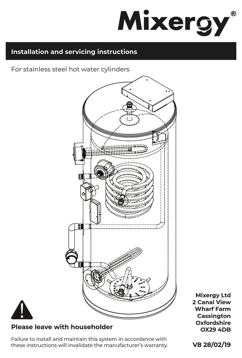
Mixergy MDC0008-02 Installation and operation manual

Installation and commissioning
instructions
MDC0008-02
For Mixergy heat exchanger modules
Failure to install and maintain this system
in accordance with these instructions will
invalidate the manufacturer’s warranty.
PLEASE LEAVE WITH HOUSEHOLDER
V15 11/08/21

2
About this module
Technical data
Exchanger construction
Exchanger rating* 44 kW
Exchanger max. primary ow rate 3/hr)
Exchanger connections
Exchanger max. primary ow temperature 80 °C
Exchanger max. working pressure (indirect)
Circulator pump rating
Exchanger equivalent coil surface area** 3 m2
The Mixergy heat pump exchanger module is designed to allow
for integration of any Mixergy cylinder with both low and high
temperature heat pumps.
This module incorporates a high surface area plate heat exchanger
and circulator pump to enable high performance heat transfer
between the heat pump and cylinder. This module replaces a
reheat speed, heat pump performance and serviceability than a
conventional system.
Tel: 01865 884343
Email: enquiries@mixergy.co.uk

Contents
2
Technical data 2
Contents 3
Included items 4
4
Hydraulic schematics 10
12
13
18
Troubleshooting
Draining the cylinder 21
Replacement parts 21

4
Included items
Exchanger performance graphs
•
• 2x 22mm compression nuts and olives
• 2x 22mm isolator valves and pipe stubs
• Installation guide
• Insulating jacket for exchanger
• Heat pump interface
0
10
20
30
40
50
10 15 20 25 30 35 40 45 50 55

5
0
5
10
15
20
25
30
35
40
45
5 10 15 20 25 30 35 40 45 50 55 60 65
Pressure drop (kPa)
Flow rate (L/min)

Installation: hydraulic
1.
cylinder.
2. Remove blanking caps from cylinder heat exchanger ports,
replace with included compression nuts and olives.
Heat
exchanger ports
pred
mounting holes
position 1
Heat
exchanger ports
pred
mounting holes
position 2

3.
4.
using supplied pipe stubs.
5.
Installation: hydraulic
IT IS RECOMMENDED TO FIT THE SUPPLIED 22mm
ISOLATOR VALVES BETWEEN THE EXCHANGER
ASSEMBLY AND THE HEAT EXCHANGER PORTS
WHEN POSSIBLE FOR EASE OF SERVICE
R

8
Installation: hydraulic
IT IS THE INSTALLER’S RESPONSIBILITY TO ENSURE
THE ASSEMBLY IS FULLY SEALED BEFORE LEAVING SITE
8.
Close the air vent cap.
10. Fit the exchanger installation jacket and supplied lagging to
exposed pipework.
FLOW
RETURN

Installation: remote mounting
pipework obstruct the normal mounting position of the exchanger
away from the cylinder. In this situation, please follow the guidance
•
exchanger assembly to the heat exchanger ports on the cylinder.
Do not exceed more than 2m of additional pipework and reduce
the number of bends in the pipework to a minimum.
•
a minimum of 3 wall mounted pipe clips within 300mm of the
assembly.
•
lagged.
•
page 10).

10
Hydraulic schematics
HP/PRIMARY FEED
HP/PRIMARY RETURN
ISOLATOR
DRAIN COCK
HOT DRAW
(22mm comp.)
COLD FEED (22mm comp.) INCOMING SUPPLY (FROM HEADER)
1/2” BSPP F (OPTIONAL FOR SHOWER PUMP)
VENT PIPE
2-PORT DIVERTER VALVE MUST
BE FITTED FOR HEAT SOURCES
CAPABLE OF EXCEEDING 70C
HONEYWELL V4043H1056 OR EQUIV.
ECOCIRC 15-4/130(N)
CIRC. PUMP
ISOLATOR
ISOLATOR
HEAT PUMP VENTED

11
HP/PRIMARY FEED
HP/PRIMARY RETURN
EXPANSION VESSEL
TUNDISH
T&P RELIEF VALVE
PRESSURE
RELIEF VALVE
TO D2 DISCH. PIPE
ISOLATOR
DRAIN COCK
PRESSURE REDUCING VALVE
STRAINER
CHECK VALVE
HOT DRAW
(22mm comp.)
COLD FEED (22mm comp.) INCOMING SUPPLY (FROM MAINS)
2-PORT DIVERTER VALVE MUST
BE FITTED FOR HEAT SOURCES
CAPABLE OF EXCEEDING 70C
HONEYWELL V4043H1056 OR EQUIV.
CALEFFI 553112 or equiv. MONOBLOC COLD WATER CONTROL VALVE
ECOCIRC 15-4/130(N)
CIRC. PUMP
ISOLATOR
ISOLATOR
HEAT PUMP UNVENTED

12
Installation: mechanical
1.
2.
on
spacers and screws).
1 2
IN THE CASE OF A 120L CYLINDER, IT IS
RECOMMENDED TO FIT THE HEAT PUMP INTERFACE
AT POSITION 1 TO ALLOW SPACE FOR THE
EXCHANGER ASSEMBLY

13
Installation: electrical
ENSURE ALL ELECTRICAL SUPPLIES ARE SWITCHED
OFF BEFORE MAKING ANY CONNECTION TO
THE UNIT. ELECTRICAL INSTALLATION MUST BE
CARRIED OUT BY COMPETENT ELECTRICIAN
AND BE IN ACCORDANCE WITH THE LATEST I.E.E.
REGULATIONS.
How the electrical interface works
The electrical interface for indirect/heat pump control on a Mixergy
cylinder works by switching the contacts on a volt free relay.
power the included circulator pump.
or otherwise interface with the heat pump depending on setup.
temperature sensor for DHW operation.
Use of a temperature probe
In the instance where control of the cylinder by the heat pump is
allow for the installation of the heat pump’s water temperature sensor.
features of the Mixergy app will be disabled and the cylinder will only
control changes need to be performed on the heat pump’s controller.

14
Installation: electrical
Recommended installation (DHW Sensor)
For heat pumps with a DHW sensor input, the recommended
1.
2.
3.
4.
5.
8.
orientation does not matter. If the heat pump sensor interface has
more than 2 terminals, please contact Mixergy directly for further
guidance.
Full schematics for this installation can be found on .
ENSURE 2-CORE CABLE USED FOR SENSOR
INTERFACE HAS A MINIMUM CSA OF 0.25 mm2
ENSURE 3-CORE CABLE USED FOR CIRCULATOR
PUMP HAS A MINIMUM CSA OF 0.5 mm2 AND A
MINIMUM VOLTAGE RATING OF 240 VAC.

15
Installation: electrical
Alternate installation (Modied S-PLAN)
1.
2.
3.
4.
5.
8.
10.
11.
12.
13.
Full schematics for this installation can be found on .
ENSURE 3-CORE CABLE USED FOR CIRCULATOR
PUMP HAS A MINIMUM CSA OF 0.5 mm2 AND A
MINIMUM VOLTAGE RATING OF 240 VAC.

Installation: electrical (DHW Sensor)
CYLINDER HP INTERFACE
HEAT PUMP CONTROLLER
FUSED 3A,
240VAC
DHW_SENS2
LT ZONE SW_L
HT ZONE SW_L
DHW_SENS1
SENSOR1
SW_L
HEAT PUMP
STAT
INDIRECT
PUMP
L
N
E
COM
NC
NO
COM
E
L
N
1
2
E
CYLINDER
INDIRECT CONTROL
CYLINDER STAT
L
N
E BR
BL
BR
BL
E
CYLINDER
EXCH. CIRC. PUMP
L
N
E
CYLINDER HP INTERFACE
HEAT PUMP CONTROLLER
FUSED 3A,
240VAC
DHW_SENS2
LT ZONE SW_L
HT ZONE SW_L
DHW_SENS1
SENSOR1
SW_L
HEAT PUMP
STAT
INDIRECT
PUMP
L
N
E
COM
NC
NO
COM
E
L
N
1
2
E
CYLINDER
INDIRECT CONTROL
CYLINDER STAT
WIRING CENTRE (HONEYWELL 42002116-002 OR EQUIV.)
DHW 2-PORT ZONE VALVE
(HONEYWELL V4043H1056 OR EQUIV.)
HEATING 2-PORT ZONE VALVE
(HONEYWELL V4043H1056 OR EQUIV.)
ORANGE
L
N
E BR
BL
BR
BL
E
BROWN
GREEN/YELLOW
BLUE
WHITE WHITE
BLUE
GREEN/YELLOW
BROWN
ORANGE
CYLINDER
EXCH. CIRC. PUMP
L
N
E

Installation: electrical (Modied S-Plan)
CYLINDER HP INTERFACE
HEAT PUMP CONTROLLER
FUSED 3A,
240VAC
DHW_SENS2
LT ZONE SW_L
HT ZONE SW_L
DHW_SENS1
SENSOR1
SW_L
HEAT PUMP
STAT
INDIRECT
PUMP
L
N
E
COM
NC
NO
COM
E
L
N
1
2
E
CYLINDER
INDIRECT CONTROL
CYLINDER STAT
L
N
E BR
BL
BR
BL
E
CYLINDER
EXCH. CIRC. PUMP
L
N
E
CYLINDER HP INTERFACE
HEAT PUMP CONTROLLER
FUSED 3A,
240VAC
DHW_SENS2
LT ZONE SW_L
HT ZONE SW_L
DHW_SENS1
SENSOR1
SW_L
HEAT PUMP
STAT
INDIRECT
PUMP
L
N
E
COM
NC
NO
COM
E
L
N
1
2
E
CYLINDER
INDIRECT CONTROL
CYLINDER STAT
WIRING CENTRE (HONEYWELL 42002116-002 OR EQUIV.)
DHW 2-PORT ZONE VALVE
(HONEYWELL V4043H1056 OR EQUIV.)
HEATING 2-PORT ZONE VALVE
(HONEYWELL V4043H1056 OR EQUIV.)
ORANGE
L
N
E BR
BL
BR
BL
E
BROWN
GREEN/YELLOW
BLUE
WHITE WHITE
BLUE
GREEN/YELLOW
BROWN
ORANGE
CYLINDER
EXCH. CIRC. PUMP
L
N
E

18
Installation: commissioning
1.
2.
3.
observed.
4.
mode. This can be done in the web/phone app or directly on the
cylinder gauge by holding both the boost up and down buttons
and releasing once the display lights blue.
5.
heat is made, circulator pump and heat pump begin running,
cylinder starts to heat.

Troubleshooting
No call for heat is made
If no call for heat is made and the cylinder is instead energizing the
primary immersion, ensure that the cylinder has been set to operate
heat is being made by the cylinder but there is no response from the
the assembly junction box. If a call for heat is made and the circulator
powers but the heat pump does not respond, double check the wiring
integration with the heat pump along with the heat pump controller
guidance.
Heat pump reporting strange temperatures
If the heat pump DHW sensor reading is either in an error state or
reporting values outside of the expected range, then the heat pump
may be set to the wrong sensor type. If the heat pump accepts
pump manual for guidance on changing the sensor type. If no such
function exists, please contact Mixergy directly for further support.
Slow charging
If the cylinder is charging slowly when charging via heat pump, ensure
that the heat exchanger circulator pump is running and that there is
Electrical fault
If an electrical fault of the controller is suspected or the electrical
system does not operate as expected, please contact Mixergy directly.
Intermittent charging
If the cylinder is only able to charge some of the time when a call for
heat is made or charging is out of sync with calls for heat, this indicates
is suspected, please ensure that the heat pump controller’s DHW
generation is unscheduled. If the latter is suspected, double check the
wiring. If a solution cannot be found, please contact Mixergy directly.

20
Troubleshooting
Immersion is being used in heat pump mode
temperature ceiling below the set temperature of the cylinder
cylinder set temperature of 55 C). If this is detected, the immersion
If this behaviour is undesirable, the set temperature of the cylinder
not permitted for sanitary reasons.
Other issues
If any other issues are suspected, please contact Mixergy directly for
further support.
Table of contents
Other Mixergy Water Heater manuals
Popular Water Heater manuals by other brands

OSO
OSO Dualstream Technical installation manual

A.O. Smith
A.O. Smith del and del Installation & operation manual

Kenmore
Kenmore 33176 - Power Miser 12 owner's manual

State Water Heaters
State Water Heaters TPG/TPO/TPD 140-140 THRU 140-720 Replacement parts list

Radiant
Radiant S 14 Installation, use and maintenance manual

GE
GE GG28T06AXK Energy guide