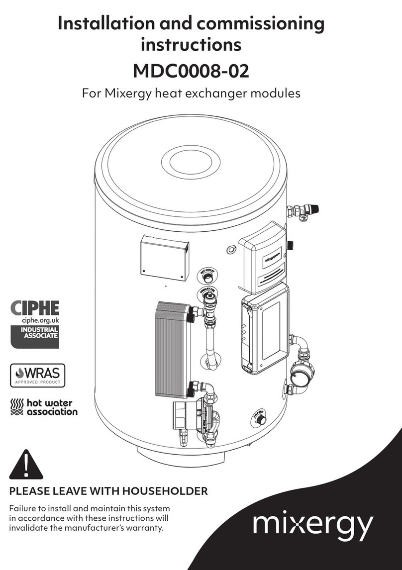
Mixergy M0008 User guide

Installation and servicing instructions
For stainless steel hot water cylinders
Failure to install and maintain this system in accordance with
these instructions will invalidate the manufacturer’s warranty.
Please leave with householder
Mixergy Ltd
2 Canal View
Wharf Farm
Cassington
Oxfordshire
OX29 4DB
V8 28/02/19
®

2
Cylinder details
Technical data
MX number
Your cylinder MX number can be found on the label placed on the front of the cylin-
der.
For all queries, please contact us:
Tel: 01865 884343
E-Mail: enquiries@mixergy.co.uk
Max. supply pressure to pressure reducing valve 1 MPa (10 bar)
Operating pressure 0.3 MPa (3 bar)
Expansion vessel charge pressure 0.3 MPa (3 bar)
Expansion relief valve setting 0.6 MPa (6 bar)
P&T relief valve setting (pressure) 0.7 MPa (7 bar)
P&T relief valve setting (temperature) 90 °C
Adjustable temperature range (digital) 50 - 65 °C
Coil max. working pressure (indirect) 0.35 MPa (3.5 bar)
Immersion heater(s) rating 230-240 V~ 2.7-3.0 kW
Immersion heater(s) specification EN 60335-2-73
Immersion heater(s) type 356 mm Incoloy
Thermostat cut-out temperature 80 °C

3
Cylinder details 2
Technical data 2
Contents 3
About your system 4
Additional components 5
Model sizes and weights 5
Design notes 6
Schematic: Direct 7
Schematic: Indirect 8
Installation: general guidelines 9
Installation: electrical 12
Installation: connectivity 19
Discharge pipework 20
Commissioning 25
Commissioning checklist 27
Problem solving 29
Draining the cylinder 31
Servicing 32
Service record 33
Replacement parts 34
Contents

4
About your cylinder
The Mixergy cylinder is a hot water storage cylinder which uses
thermal stratification. This system works by heating water at the
top of the cylinder first and then diffusing cold water from the bot-
tom of the cylinder into this hot portion during heating.
This ‘top-up’ technology allows the Mixergy cylinder to selectively
heat (or ‘charge’) the water, improving reheat performance, reduc-
ing heat losses and improving available renewable capacity.
For more information on how your cylinder works and how to get
the most out of your system, please refer to the user guide.
15 ˚C
55 ˚C
15 ˚C
55 ˚C

5
Additional components
• Monobloc kit incl. pressure reducing valve, check valve, pres-
sure and temperature relief valve and expansion relief valve
• Tundish
• Expansion vessel incl. mounting bracket and flexible hose
• 3 kW immersion heater(s) 1.3/4” BSP (fitted)
• High limit thermostat (indirect only, fitted)
• 2-port diverter valve V4043H1056 (indirect only)
• Powerline to ethernet adapter TL-PA4010
• Ethernet cable
• User guide
• Warranty statement
Model sizes and weights
Cylinder
capacity (L) 120 150 180 210 300
Nominal
dia. (mm) 475 545 475 545 475 545 475 545 475 545
Cylinder
height
(mm)
1255 990 1520 1190 1800 1370 1980 1560 -- 2130
Empty weights (kg)*
Direct 27 27 34 34 39 39 42 42 -- 56
Indirect
(single coil) 31 31 39 39 43 43 46 46 -- 61
Indirect
(dual coil) -- -- -- 41 -- 46 -- 49 -- 64
Full weights (kg)*
Direct 147 147 184 184 219 219 252 252 -- 356
Indirect
(single coil) 151 151 189 189 223 223 256 256 -- 361
Indirect
(dual coil) -- -- -- 191 -- 226 -- 259 -- 364
*For systems with external heat exchangers fitted, add 2 kg to the
cylinder weight.

6
Design notes
The Mixergy cylinder is currently available in two basic variations:
• Mixergy Direct - Provides hot water heated by electricity and is
designed primarily for use with off peak electricity.
• Mixergy Indirect - Provides hot water either by electricity or an
internal primary coil which is designed for use with electric,
gas or oil fired boilers.
In addition, Mixergy cylinders can be fitted with the following op-
tions:
• External heat exchanger for use with electric, gas or oil fired
boilers and heat pump systems.
• Dual primary element for use with a PV diverter.
The unit should be handled with care in order to avoid damage. It
should be stored upright in a dry place.
Unvented hot water cylinders must not be used with
solid fuel boilers as the energy source.
All models are factory fitted / supplied with immer-
sion heaters that have built-in thermal cut-outs. Im-
mersion heaters without thermal cut-outs must not
be fitted.
All unvented installations must be fitted with a pres-
sure reducing valve (supplied) and P&T relief valve
(fitted). These must not be removed or used for any
other purposes than what they are designed for.

7
Schematic: Direct
1Hot draw off Primary immersion
Cold feed P&T relief valve
Controller Tundish and discharge pipe
Cold water control group Pump assembly
Expansion vessel Backup immersion (if fitted)
Expansion relief valve
2
3
4
5
6
7
8
9
10
11
12
3
5
4
6
9
11
10
7
8

8
Schematic: Indirect
1Hot draw off Indirect coil ports
Cold feed P&T relief valve
Controller High limit safety stat
Cold water control group Indirect junction box
Expansion vessel Tundish and discharge pipe
Expansion relief valve Pump assembly
Primary immersion Backup immersion (if fitted)
2
3
4
5
6
7
8
9
10
11
12
13
14
12
3
5
4
6
12
14
13
7
9
8
10
11

9
Installation: general guidelines
The installation area should be able to cope with the weight, in-
coming pipes and discharge pipe when full. Full weights are listed
on page 5 of this booklet.
Positioning of the cylinder
Position of the cylinder should suit the installation; all connections
should be to the front for ease of access. Ensure suitable space is
left for access for repair and/or replacement of immersions and
valves etc. Ensure atleast 300mm of vertical clearance above the
cylinder. Refer to page 5 for cylinder heights and the diagram
below for guidelines on space requirements:
Nominal di-
ameter nD
(mm)
Space re-
quirement S
(mm)
475 610
565 700
In the case of an unvented installation, install of this
product should only be carried out by a “competent
operative” i.e. the installer must have attended a
recognised course in unvented hot water systems or
received appropriate training in their apprenticeship.
All registered operatives should carry an Identifi-
cation Card issued by the institute of Unvented Hot
Water Systems.
610 850
S
S
nD

10
Installation: general guidelines
Unvented installations
In the case of an unvented installation, installers should ensure
incoming mains pressure is less than 1 MPa (10 bar) and that local
authority approval for installation of unvented systems is granted.
Ensure adequate flow rate is available.
Use of flux and sterilisation
Excessive use of flux can damage the unit and especially the valves
and expansion vessel (if supplied). Avoid over-use and ensure the
system is fully flushed of any debris or flux after connection. If a full
sterilisation of all the pipework including the cylinder is required
then a complete drain down and flush of the unit is essential. A
simple flush through with water is not adequate in removing all
sterilising solution within the cylinder. Under no circumstances
should sterilising solution be left in the cylinder any longer than re-
quired (seek dosage requirements from chemical manufacturer).
Pipework and cold water control group
The unit should be piped in with a nominal 22mm pipe to ensure
adequate flow rate. The unit is supplied with a monobloc pressure
reducing valve that has a set pressure of 3.0 bar. The valve also
consists of a serviceable strainer, non return valve, expansion relief
valve, connection for an expansion vessel and balanced cold feed
supply. We would strongly recommend fitting an isolating valve
(not supplied) prior to the monobloc valve for ease of maintenance
at a later date. Under no circumstances should an insolating valve
be fitted between the expansion valve and the storage cylinder.
Fitting a drain valve
Please ensure that a drain valve is fitted to the lowest part of the
unit, The drain valve must be fitted as low as possible so that at
least 80% of the cylinder’s total capacity can be drained off.
Connecting the hot draw
It is recommended that a 90° elbow be fitted within 100 mm of
the hot draw to minimize heat losses due to thermosiphoning.

11
Installation: general guidelines
The relief valves are only to be used for relief dis-
charge purposes. No valves should be fitted between
the relief valves and the cylinder.
Indirect units and electrical wiring
On Indirect Units, where a coil is fitted to the cylinder, the supplied
two port motorized zone valve must be fitted in accordance with
the instruction details supplied for the appropriate installation.
Maximum working pressure of the coils is 3.5 Bar. All electrical
wiring to electronics, zone valve and immersion heaters must be
earthed and to current IEE Wiring Regulations.
Positioning the tundish
The tundish, which shows visible discharge from the relief valves, is
to be in a prominent, visible and safe position away from any elec-
trical devices. See discharge and safety devices on page 16.
Checking the P&T relief valve
The pressure and temperature relief valve is set at 7 bar and 90°C
and is factory fitted and sealed prior to dispatch. Whilst we en-
deavour to make sure there are no leaks from the seal, we would
advise checking the connection as the valve may have been dis-
rupted in transit.
Fitting the expansion vessel
The expansion vessel should be checked and if required charged
at 3.0 bar. The vessel should be mounted securely to the wall or
sufficient support with the fixing kit supplied. The connection
should be made between the vessel and monobloc kit.
The electrical supply to the controller and any addi-
tional immersion heaters must be installed by a quali-
fied electrician.

12
Installation: electrical
External wiring
Mixergy cylinders come supplied with cable included. The pur-
pose and installation requirements for each cable are given below.
Layout of the internal junctions within the controller are also given
should replacement cables be required.
Supply
The white 3-core (L+N+E) cable
labelled ‘supply’ must be con-
nected to the household’s peak
supply via a dedicated 16A MCB
protected circuit with a 20A DP
switch.
Sense
The black 3-core (L+N+E) cable
labelled ‘sense’ can be used
to integrate the Mixergy cylin-
der with any existing timers or
controllers i.e. economy 7 timer
or a hive controller. See ‘External
controller wiring’ on page 17
for more details on wiring in an
external controller.
Internal wiring junctions for supply cable.
Connections highlighted in black.
Internal wiring junctions for sense cable.
Connections highlighted in black.
ENSURE ALL ELECTRICAL SUPPLIES ARE SWITCHED
OFF BEFORE MAKING ANY CONNECTION TO THE
UNIT. ELECTRICAL INSTALLATION MUST BE CARRIED
OUT BY COMPETENT ELECTRICIAN AND BE IN AC-
CODRANCE WITH THE LATEST I.E.E. REGULATIONS.
The sense cable is attached to volt free contacts
within the controller and can be safely cut short if not
required.

13
Installation: electrical
Indirect wiring
Mixergy indirect cylinders can be wired into both S-plan and
Y-plan heating configurations. Please use the following instruc-
tions for reference.
These instructions are only for the wiring of the cylin-
der and cannot be used as a reference for a complete
central heating system.
Indirect and external controller wiring
Indirect cylinders are wired via the indirect junction box. The lo-
cation of this box is given in the schematic on page 8. Please
use the diagrams on page 14 for reference. Full schematics are
given on pages 15 and 16.
Wiring with 2 port zone valve (S-plan)
• Connect a 5A fused supply (L) to the indirect junction box ter-
minal labelled ‘N’.
• Connect earth to the indirect junction box terminal labelled
GND.
• Connect the 2 port valve brown (Br) cable to the indirect junc-
tion box terminal labelled ‘L1’.
Wiring with 3 port mid position valve and 2 port zone valve
(Y-plan)
• Connect a 5A fused supply (L) to the indirect junction box ter-
minal labelled ‘N’.
• Connect earth to the indirect junction box terminal labelled
GND.
• Connect the 2 port valve brown (Br) cable to the indirect junc-
tion box terminal labelled ‘L1’.
• Connect the 3 port valve grey (Gr) cable to the indirect junction
box terminal labelled ‘L2’
• Connect the 3 port valve orange cable to the 2 port valve or-
ange cable.

14
Installation: electrical
These wiring diagrams only serve as examples, the
specific cable used should suit the installation.
N
L1
L2
N
L1
L2
Wiring diagram with 2 port
zone valve (S-PLAN)
Wiring diagram with 3 port mid position
valve and 2 port zone valve (Y-PLAN)

15
Installation: electrical

16
Installation: electrical

17
Installation: electrical
External controller wiring
Mixergy systems can be connected to an external controller using
the sense cable as follows:
• Connect the brown (L) cable to the external controller ‘DHW
ON’ junction.
• Connect the blue (N) cable to neutral.
• Connect the green and yellow (E) cable to ground.

18
Installation: electrical
PV diverters
If your Mixergy cylinder is equipped for use with a PV diverter, a
dual immersion will be fitted to replace the primary immersion
shown in the schematics on page 7 and 8. This immersion
will come factory wired into the Mixergy system with an additonal
3-core (L+N+E) cable labelled ‘solar feed’ that should be wired into
your PV diverter as specifed by the manufacturer. If a replacement
cable is required, please use the wiring diagram below for refer-
ence.
Ensure both supplies are isolated before performing
work. Check continuity between immersion contacts
before wiring. DO NOT CONNECT SOLAR PV AND
MAINS LIVE OR NEUTRAL TOGETHER.
EN
LL
NE
Mixergy Solar PV

19
Installation: connectivity
Installing the powerline adapter
The Mixergy cylinder requires internet connectivity to allow for full
control of the system. Connection to the cylinder can be made us-
ing the provided ethernet to powerline adapter or the cylinder can
be paired with an existing HomePlug AV network if available.
Powerline connectivity between the cylinder and
internet router is only possible in houses where both
the cylinder and adapter are powered from the same
electrical phase. For houses with 3 phase power,
please ensure the cylinder and powerline adapter are
powered from the same phase or use a direct ether-
net connection to the cylinder.
1. Plug the powerline adapter into a wall socket within 2m of the
internet router.
2. Plug the powerline adapter into the internet router using the
included 2m ethernet cable.
1
2

20
Discharge pipework
Discharge pipes from safety devices
• Safety devices such as temperature relief valves or combined
temperature and pressure relief valves should discharge either
directly or by way of a manifold via a short length of metal pipe
(D1) to a tundish.
• The diameter of discharge pipe (D1) should be not less than the
nominal outlet size of the safety device, e.g. temperature relief
valve.
• Where a manifold is used it should be sized to accept and dis-
charge the total discharge from the discharge pipes connect-
ed to it.
• Where valves other than a temperature and pressure relief
valve from a single unvented hot water system discharge by
way of the same manifold that is used by the safety devices,
the manifold should be factory fitted as part of the hot water
storage system unit or package.
Tundish
• The tundish should be vertical, located in the same space as
the unvented hot water storage system and be fitted as close
as possible to, and lower than, the safety device, with no more
than 600mm of pipe between the valve outlet and the tundish.
Note: To comply with the Water Supply (Water Fittings) Regu-
lations, the tundish should incorporate a suitable air gap.
• Any discharge should be visible at the tundish. In addition,
where discharges from safety devices may not be apparent,
e.g. in dwellings occupied by people with impaired vision or
mobility, consideration should be given to the installation of a
suitable safety device to warn when discharge takes place, e.g.
electronically operated.
This manual suits for next models
1
Table of contents
Other Mixergy Water Heater manuals
Popular Water Heater manuals by other brands

OSO
OSO Dualstream Technical installation manual

A.O. Smith
A.O. Smith del and del Installation & operation manual

Kenmore
Kenmore 33176 - Power Miser 12 owner's manual

State Water Heaters
State Water Heaters TPG/TPO/TPD 140-140 THRU 140-720 Replacement parts list

Radiant
Radiant S 14 Installation, use and maintenance manual

GE
GE GG28T06AXK Energy guide