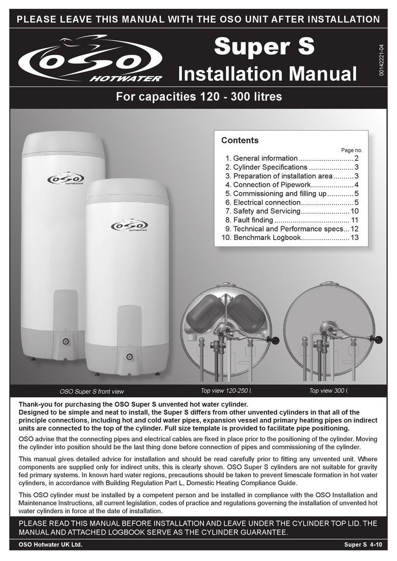
OSO Dualstream Technical document

TECHNICAL AND INSTALLATION MANUAL
HOT WATER
CAPACITY
120 - 380 LITRES
BY
OSO HOTWATER (UK) LIMITED
This manual gives detailed advice for installation and should be read
carefully prior to fitting the OSO Dualstream. Where components are
supplied only for indirect units, this is clearly shown.
The OSO Dualstream must be installed by a competent person and in
accordance with current Building Regulations including Guidance
Document G3.
Drawings on pages 1-18 show
22mm valves on cold water supply.
For 28mm see page 19.
IM/OD/1

1
CONTENTS
INTRODUCTION 1
1-1 Introduction .......................................................... 2
1-1.1 How the OSO Dualstream System Works.2
1-1.2 System Contains.................................................. 2
1-1.3 System Features.................................................. 2
1-1.4 Central Heating System.................................... 3
1-1.5 Models Available .................................................. 3
OPERATOR CONTROLS 2
2-1 Hot Water Temp. ............................................... 4
2-1.1 Hot Water Control - Heating System .......... 4
2-1.2 Hot Water Control - Immersion Heater ...... 4
2-2 Hot Water Overheating................................... 6
2-2.1 Water Heated by Heating System................ 6
2-2.2 Water Heated by Immersion Heater............ 6
2-3 Shut Off Valves................................................... 6
2-3.1 Stop Cock................................................................ 7
2-3.2 Double Check Valve ........................................... 7
2-3.3 Cold Water Shut Off Valve............................... 7
2-3.4 Supply Water Shut Off Valve .......................... 7
2-3.5 Hot Water Shut Off Valve ................................. 7
2-4 Pressure Relief ................................................... 7
2-5 Servicing ................................................................ 7
TECHNICAL INFORMATION 3
3-1 System Components....................................... 8
3-2 Specifications...................................................... 8
3-2.1 Cylinder .................................................................... 8
3-2.2 Accumulator .......................................................... 8
3-2.3 Pipes.......................................................................... 8
3-2.4 Electrics.................................................................... 8
3-3 Wiring....................................................................... 9
3-3.1 Immersion Heater ................................................ 9
3-3.2 Wiring Layout S Plan .........................................10
3-3.3 Wiring Layout Y Plan..........................................11
INSTALLATION 4
4-1 Building Control ................................................12
4-1.1 Regulations ............................................................12
4-1.2 Electrical Regulations........................................12
4-2 Installation ............................................................12
4-2.1 Positioning ..............................................................12
4-2.2 Unvented Hot Water Cylinder ........................12
4-2.3 Accumulator ...........................................................13
4-2.4 Tundish.....................................................................13
4-2.5 Discharge Pipe .....................................................13
4-2.6 Scale Protection...................................................14
4-2.7 Pipework..................................................................14
4-2.8 OSO Dualstream Components .....................14
4-2.9 Connections to OSO Dualstream.................14
4-3.0 Direct Cylinders....................................................14
COMMISSIONING 5
5-1 Commissioning Checks................................15
5-1.1 Commissioning Procedure ..............................15
5-2 Handing Over ......................................................15
SERVICING 6
6-1 Routine Service..................................................16
6-1.1 Service Procedure...............................................16
SPARE PARTS 7
7-1 Spare Parts...........................................................17
SECONDARY RETURN 8
8-1 Secondary Return.............................................17
OSO DUALSTREAM 9
9-1 OSO Dualstream................................................18
CONNECTIONS 10
10-1 28mm Connections..........................................19
FAULT DIAGNOSIS 11
11-1 Fault Diagnosis ..................................................19

1-1 INTRODUCTION
This Handbook has been compiled to assist in the Installation and Operation of the OSO Dualstream domestic hot and cold
water system. The Installer of the system should give full operating instructions to the householder for the OSO Dualstream
System.
1-1.1 How the OSO Dualstream system works
Fig.1-1 is a schematic illustration of a typical OSO Dualstream system showing how it works.
Option A is used when the accumulator is installed remotely from the unvented cylinder and requires an accessory pack
containing pressure reducing valve, expansion relief valve expansion vessel and bracket, available at additional cost and
should be ordered with the system.
1-1.2 System Contains
1. An unvented hot water cylinder pre-plumbed with all valves and controls with easy access pipe connections for quick,
trouble-free installation.
2. Cylinder Thermostat and High Limit Thermostat.
3. An Accumulator (cold water storage) and associated fittings.
4. One two port motorised valve for connection to heating system flow to cylinder (Indirect only).
5. The OSO Dualstream is supplied with an adjustable pressure reducing valve. This means pressure to all mains water
outlets can be adjusted between 0.5 bar to 5 bar.
1-1.3 System Features
1. All Taps and Showers are at maximum ‘Mains Pressure’.
2. Equal pressure at Hot and Cold Taps.
3. No pressure drop when more than one Tap is in use.
4. More than 25% less pipework than traditional systems.
5. No loft storage tank.
6. Completely sealed system - all Cold Taps are classed as wholesome water.
2
INTRODUCTION 1
Fig. 1-1 Schematic illustration
(Indirect unit)
Rubber expanding
bladder inside vessel.
Pressure is maintained
at maximum
‘Mains Pressure’.
Pressure relief valve
vents excess pressure
from Hot Water System.
Hot Water Cylinder is at
‘Mains Pressure’ due to
incoming cold.
Cylinder with immersion
heater. Water can be heated
by any conventional method.
Existing
Mains Supply
Hot Supply
Option A
Non-return valve. As
water is used system
is equalised to
maximum ‘Mains
Pressure’.
Boiler Return
Secondary Return
Boiler Flow
Air Pressure
Diaphragm
Accumulator
Mains Water

3
INTRODUCTION 1
1-1.4 Central Heating System
The OSO Dualstream system does not affect the Central Heating installation. However consideration has to be
given to the best method of connection and control of the heating system to the indirect cylinder.
1-1.5 Models Available
Below is a typical selection of the systems available, other combinations can be tailored to suit requirements.
Model Accumulator (Cold Water Storage)
Weight Full (Kg)
Hot Water
Storage Capacity
(L)
Cylinder
Type
Hot Water Cylinder (Direct RD Indirect RI)
20 R
120
120
160
580
720
All sizes are nominal
Very low mains flow rates may require larger or multiple accumulators
Weight Full (Kg)
Diameter
Height
Diameter
Height
Nominal Capacity
(L)
Vessel
Type 19608
100
86
440
890
Weight Full (Kg)
Hot Water
Storage Capacity
(L)
Cylinder
Type
20 R
120
120
160
580
720
20 R
150
150
190
580
900
20 R
200
200
250
580
1150
Weight Full (Kg)
Diameter
Height
Diameter
Height
Nominal Capacity
(L)
Vessel
Type 18891
170
150
535
995
Weight Full (Kg)
Hot Water
Storage Capacity
(L)
Cylinder
Type
20 R
200
200
250
580
1150
20 R F1
200
250
310
580
1400
Weight Full (Kg)
Diameter
Height
Diameter
Height
Nominal Capacity
(L)
Vessel
Type 18892
240
205
540
1220
Weight Full (Kg)
Hot Water
Storage Capacity
(L)
Cylinder
Type
20 R F1
250
250
310
580
1400
20 R F1
300
300
365
580
1600
Weight Full (Kg)
Diameter
Height
Diameter
Height
Nominal Capacity
(L)
Vessel
Type 18893
310
255
540
1500
Weight Full (Kg)
Hot Water
Storage Capacity
(L)
Cylinder
Type
20 R F1
300
300
365
580
1600
20 R F1
380
380
462
580
2100
Weight Full (Kg)
Diameter
Height
Diameter
Height
Nominal Capacity
(L)
Vessel
Type 18894
450
385
665
1550

2-1 HOT WATER TEMPERATURE
2-1.1 Hot Water Control - Heating System (Indirect only)
When the hot water is heated by the heating system the temperature of the hot water at the taps is controlled by the Cylinder Thermostat.
This controls a Motorised Valve that opens and closes the flow from the heating system.
The temperature range is 45°C to 75°C.
Recommended setting is between 50°C minimum and 70°C maximum.
1 Indirect Units
Motorised valve
To comply with regulations governing the installation of indirect unvented
cylinders, a motorised valve must be fitted in the primary flow. Your OSO unit has
been supplied with a two port motorised valve, which will act as a positive energy
cut-out should the safety cut-out operate. The motorised valve will also control the
temperature of the domestic stored water via the cylinder thermostat, which is
located in the electrical box. The unit should be installed on an “S’’ or “Y’’ plan
system. Please follow the instructions carefully. All electrical connections must
conform to current IEE wiring regulations. The working thermostat which controls
the temperature of the domestic hot water (see fig. 2) is adjustable between 45°C
to 75°C. A safety cut out is also incorporated within the thermostat and will
operate at 85°C ± 3°C. Should the safety cut out be brought into operation, the
motorised valve will operate and close down the primary flow to the cylinder. To
reset the safety cut out and the motorised valve the reset button must be pressed
in (see fig. 2). If using a 6-wire 28mm or 1’’ BSP V4043H on either circuit the white
wire is not needed and must be made electrically safe.
2-1.2 Hot Water Control - Immersion Heater
When the hot water is heated by the electric Immersion Heater, the temperature
of the hot water at the taps is controlled by the Immersion Heater Thermostat.
This is located under the electrical box cover, left hand thermostat.
2 Direct units
Wiring instructions for the water heaters are located on the reverse side of the lid.
Follow the wiring instructions connecting the live, neutral and earth as
indicated. All internal wiring is factory mounted. Each immersion heater has
a working thermostat adjustable between 45°C to 75°C. A safety cut-out is
also incorporated within the thermostat and will operate at 85°C ± 3°C.
Should this happen, press the reset button.
Important: Before resetting the safety cut-out or altering the thermostat
setting, isolate electrical supply to the unit prior to removal of the lid.
Ensure the lid to the electrical box is replaced correctly and the
retaining screw is fitted.
The lower immersion heater should be connected to the off peak supply
(if available) whilst the top immersion heater can be connected to the day
tariff. The immersion heater can be connected to the mains supply through a
water heater controller (Contact your local electricity company if in doubt).
WARNING: When the cover is removed electrical live terminals are
exposed.
ALWAYS TURN OFF THE ‘WATER HEATER’ SWITCH BEFORE
REMOVING COVER.
The temperature range is 45°C to 75°C.
Recommended setting is between 50°C minimum and 70°C maximum.
The electrical connection to the immersion heater must conform to
current IEE wiring regulations. The unit must be permanently connected
to the electrical supply through a double-pole linked switch with a
minimum break capacity of 13 amps.
4
OPERATOR CONTROLS 2
Fig. 2-1a Hot Water Control
Adjustment
Screw
LN
Fig. 2-1b Immersion Heater Thermostat
Return to Boiler
Motorised valve
Flow from Boiler
Pole Switch

5
OPERATOR CONTROLS 2
IMPORTANT HEALTH AND SAFETY INFORMATION FOR INSTALLERS AND SERVICE ENGINEERS
HEALTH AND SAFETY AT WORK ACT 1974
CONSUMER PROTECTION ACT 1987
COSHH REGULATIONS 1988
MANUAL HANDLING OPERATIONS REGULATIONS 1992
The regulations set no specific requirements such as weight limits. However common sense still has to be used
based on an ergonomic approach for each individual.
The following information is given as a requirement of the above legislation.
Great care is taken to ensure that OSO Dualstream systems are designed and manufactured to meet general
safety requirements when properly used and installed as recommended in this manual.
It is the responsibility of Users and Engineers to ensure that adequate protective clothing and glasses are worn
when working with the OSO Dualstream system.
SEALS AND INSULATION
Insulation and sealing materials are used in the construction of the OSO Dualstream cylinders. Units are sealed
and when used in the manner for which they are intended the insulating and sealing materials do not present any
known hazard. However always observe the following recommendations:-
1. Avoid inhalation of fibres or dust, wear face mask.
2. Avoid eye contamination by fibres or dust – wear eye protection.
3. As far as possible avoid any skin contact with Fibreglass Insulation, Glass Rope, Mineral Wool, Insulation
Pads and Ceramic Fibre.
OTHER MATERIALS
SEALANTS, ADHESIVES AND PAINTS
Sealants, Adhesives and Paints are used in the construction of the OSO Dualstream components. When used in
the manner for which they are intended they do not present any known hazard.
ELECTRIC
All Cylinders have electrical supply of 240v (enough to endanger life) connected to the Immersion Heater. Always
isolate during adjustment, servicing and repair.
OSO (UK) will not accept responsibility for any damage or personal injury caused by not giving due
consideration to the above safety recommendations.
All replacement parts must be supplied by OSO HOTWATER (UK) LIMITED.
To obtain the address of a local stockist contact:
OSO HOTWATER (UK) LIMITED
E15 Marquis Court, Team Valley Trading Estate, Gateshead, Tyne & Wear, NE11 0RU.
Tel: (0191) 482 0800 Fax: (0191) 491 3655
Email : technical.uk@oso-hotwater.com - spareparts.uk@oso-hotwater.com - sales.uk@oso-hotwater.com
www.oso-hotwater.com

6
OPERATOR CONTROLS 2
Fig. 2-2a High Limit Thermostat
Hot Supply
Option A Cylinder with immersion heater.
Water can be heated by any
conventional method.
Pressure relief valve
vents excess pressure
from Hot Water System.
Hot Water Cylinder is
at ‘Mains Pressure’
due to incoming cold.
Rubber expanding
bladder inside vessel.
Pressure is maintained
at maximum ‘Mains
Pressure’
Air Pressure
Diaphragm
Accumulator
Mains Water
Existing
Mains Supply
Non-return valve. As
water is used system is
equalised to maximum
‘Mains Pressure’.
(Indirect unit)
2-2 HOT WATER OVERHEATING
2-2.1 Water Heated by Heating System
When the hot water is heated by the heating system a High Limit
Thermostat prevents the water within the Cylinder overheating.
In the event of the water temperature within the Cylinder reaching
85°C the thermostat will trip and close the Motorised Valve shutting
off the flow from the heating system - see fig. 2-2a.
The High Limit Thermostat is a manual reset type, this means that
it has a button that pops out when the thermostat has been tripped
by overheating - see fig. 2-2a.
To reset the system after overheating allow time for the water to
cool, or run off some hot water, then remove the electrical box cover
and press the High Limit Thermostat manual reset button.
If the High Limit Thermostat trips more than once, switch off the
heating system and Immersion Heater and contact your installer.
2-2.2 Water Heated by Immersion Heater
A safety cut-out is also incorporated within the thermostat and will operate at 85°C ± 3°C. Should this happen,
press the reset button.
WARNING: When the cover is removed electrical live terminals are exposed.
ALWAYS TURN OFF THE ‘WATER HEATER’ SWITCH BEFORE REMOVING COVER.
Note: The High Limit temperature of 85°C is factory set and cannot be changed.
2-3 SHUT OFF VALVES
The OSO Dualstream installation will
have a number of shut off valves, the
location of these will be dependent on
the installation - fig. 2-3a shows a
typical layout.
IMPORTANT:
Before closing ANY valve:-
1. Switch OFF the Electric
Immersion Heater.
2. Turn OFF the Heating System.
Note: When operating the stop cock
turn the valve fully open then close
1⁄2turn, this prevents the valve
sticking.
Fig. 2-3a Typical Shut Off Valve Locations
High
Limit
Adjustment
screw
Cylinder thermostat located
in electrical box

2-3.1 Stop Cock
Normally located at the point where the mains supply enters the dwelling.
Shuts off the mains water supply to the dwelling.
2-3.2 Double Check Valve
Normally located after Stop Cock.
Shuts off the mains water supply to the dwelling and prevents Backflow.
2-3.3 Cold Water Shut Off Valve
Normally located in the cold feed close to the Cylinder.
Shuts off the cold water to the taps.
2-3.4 Supply Water Shut Off Valve
Normally located where the cold supply connects to the combination valve on the Cylinder.
Shuts off the cold supply to the Dualstream system.
2-3.5 Hot Water Shut Off Valve
Normally located where the Domestic Hot Water feed comes from the Cylinder.
Shuts off the hot water to the taps.
2-4 PRESSURE RELIEF
The OSO Dualstream installation has a Pressure Relief Valve normally mounted on the cylinder. In the event of the
pressure within the system becoming too high, the Expansion Relief Valve will open, venting the pressure.
A tundish will be fitted in the system, this should be located in a position where it can be seen. This device gives
a visual warning that pressure is being vented as water.
In the event of water being seen at the tundish do the following:-
1. Turn ON a hot tap to relieve the pressure.
2. Turn OFF the Electric Immersion Heater.
3. Turn OFF the Heating System.
4. Investigate possible cause for high pressure e.g:-
i Cylinder Thermostat is set too high.
ii Mains water is not on or fully on.
iii Restriction in hot water pipework.
5. Contact the installer before restarting the system.
2-5 SERVICING
It is recommended that the system is inspected by an approved engineer
once per year.
The service procedure is included in section 6-1.1.
7
OPERATOR CONTROLS 2
CLOSED
OPEN
Fig. 2-3b Valves
Fig. 2-4 Tundish
Note: The Tundish should remain
in view do not box it in or cover it up.

Hot Supply
Option A
7
12 6
10
A
J
B
3
14
5
4
9
2
8
TECHNICAL INFORMATION 3
3.1 SYSTEM COMPONENTS TYPICAL LAYOUT AND CONNECTIONS
3.2 SPECIFICATIONS
3-2.1 Cylinder
Maximum Water Supply Pressure..........................6.0 Bar
Operating Pressure .......................................................3.5 Bar
Pressure and Temperature Relief Valve....10 Bar/90°C
Maximum Temperature.....................................................75°C
Cylinder Thermostat............................range 45°C to 75°C
Recommended Setting...................50°C min - 70°C max
High Limit Thermostat .....................................fixed @ 85°C
Immersion Heater
Voltage ..............................................................................240v
Power .................................................................................3kW
Motorised Valve.............................................................V4043H
3-2.2 Accumulator
Membrane .................................Butyl for wholesome water
Maximum pressure .........................................................10 Bar
Factory set pressure.........................................................2 Bar
3-2.3 Pipes
All pipes should be sized to suit application.
3-2.4 Electrics
All systems are supplied for 240V SINGLE PHASE.
1. Accumulator (Cold Water Storage)
2. Unvented Cylinder
3. Cylinder Thermostat (Indirect)
4. Immersion Heater Thermostat
5. Immersion Heater
6. Expansion Relief Valve
7. Pressure Reducing Valve
9. Pressure Relief Valve & Temperature
Relief Valve
10. Tundish
12. Cold Main Shut Off Valve
14. Cylinder Drain Cock
15. Tee Connection
A. Water from system
B. Accumulator Drain Cock
C. Controlled action diaphragm
D. Gas charge
E. Gas charge valve
F. Internal clench ring
G. Threaded nut for pum stand installation
H. Air flow design to reduce condensation
I. Diffuser directs flow up and out
Note: All items numbered are supplied.
The accumulator must be set at between 1 and 1.5
bar below the pressure reducing valve setting.
Minimum accumulator pressure 0.5 bar (7 PSI).
If there is an incoming pressure of 3.5 bar or over DO
NOT adjust the accumulator pressure. You should only
take air out of the accumulator and not pump it up on
installation.
3.1a SCHEMATIC LAYOUT
(Indirect unit)
Accumulator
H
F
D
E
C
1
G
15

9
TECHNICAL INFORMATION 3
3-3 WIRING
3-3.1 Immersion Heater and Thermostat
The immersion heater must be permanently connected
to the electrical supply through a double-pole linked
switch with a minimum break capacity of 13 amps.
Please use the cable glands supplied to protect and fix
electrical cables at cable entry points.
Immersion Heater 240 V - 1 phase
WARNING: Isolate from main electricity supply before
any adjustments are made.
IMPORTANT!
1. WATER IN BEFORE POWER ON.
2. All internal wiring is factory mounted. Please do
not touch.
3. Regulations require competent person.
4. Check wiring is in accordance with diagram.
5. The safety cut-out operates if:
- Wiring is incorrect
- The immersion heater is defective
- Thermostat is set too high or is defective.
Reduce thermostat setting and press the reset button.
If still out of operation, contact competent person.
Immersion heater, part no. 71255.
Thermostat, part no. 80020.
Fig. 3-3a
IMMERSION HEATER THERMOSTAT
(LEFT HAND THERMOSTAT)
WIRING DIAGRAM

10
TECHNICAL INFORMATION 3
3-3.2 S Plan Wiring Layout (Indirect only)
For Other Boilers Refer To Boiler Manufacture
Immersion Heater
Thermostat
(Left Hand)
CylinderThermostat
(Right Hand)

11
TECHNICAL INFORMATION 3
3-3.3 Y Plan Wiring Layout (Indirect only)
For Other Boilers Refer To Boiler Manufacture
Immersion Heater
Thermostat
(Left Hand)
Cylinder Thermostat
(Right Hand)

12
INSTALLATION 4
4-1 BUILDING CONTROL
To install an OSO Dualstream System the installer must be fully competent, suitably qualified and possess any
applicable licence that may be required by the local inspectorate for installation of an unvented hot water storage
system.
In some areas the Local Authority may require notification by means of a building notice or by the submission of
full plans for the proposed installation of an unvented hot water storage system.
4-1.1 Regulations
The Water Byelaws and Current Building Regulations should be considered when installing an OSO
Dualstream System.
4-1.2 Electrical Regulations
All wiring must be to current lEE Wiring Regulations.
4-2 INSTALLATION
4-2.1 Positioning
It is the responsibility of the installer to ensure the safe handling of the OSO Dualstream components in accordance
with current Health and Safety Legislation (See page 3 for weights).
If the unit is sited where it could be subjected to frost i.e. in an outhouse or garage, adequate frost protection must
be provided, this should include an overriding frost stat wired so that the system is heated in the event of low
temperature.
The floor must give adequate support to the unit when full. (See page 3 for weights).
For maintenance purposes leave at least 500mm at the front of the unit.
The installer must ensure the space available is adequate for the cylinder and accumulator being fitted.
Note: Consult the Building Regulations for safe floor loadings.
4-2.2 Unvented Cylinder
The unvented cylinder can be sited anywhere within the thermal envelope of the dwelling. If the unit is to be sited
in an outhouse or garage, adequate frost protection must be provided; this should include an overriding frost stat
so that the system is heated in the event of low temperature.
The floor must give adequate support to the cylinder when full (See page 3 for weights). Consult the Building
Regulations for safe floor loadings.
For maintenance purposes adequate access must be available around the cylinder. Access of at least 100mm is
required above the cylinder. The cylinder must be installed vertically.

13
INSTALLATION 4
4-2.3 Accumulator
The accumulator must be installed in any convenient location within the dwelling. If the accumulator is to be sited
in an outhouse or garage, adequate frost protection must be provided; this should include an overriding frost stat
so that the system is heated in the event of low temperature.
The accumulator must be installed vertically. Legs and self-tapping screws are supplied for floor fixing.
100mm minimum access is required at the top of the accumulator for adjusting the air charge above or below the
pre-set charge.
Do not fit a non-return valve between the accumulator and the unvented cylinder.
IMPORTANT: The Accumulator must be set between 1 and 1.5 bar below the pressure reducing valve
setting. Minimum accumulator pressure is 0.5 bar (7PSI). If there is an incoming pressure of 3.5 bar or
over DO NOT adjust the accumulator pressure. You should only take air out of the accumulator and not
pump it up on installation
Note: As OSO Dualstream is a sealed system the pressure at the
taps is not affected by the height of the cold water storage.
4-2.4 Tundish
The Tundish must be installed so that it is clearly visible to the householder.
A typical arrangement for the Tundish discharge is shown in fig. 4-2a. Refer to the applicable Building Regulations
for specific details of Tundish installation.
4-2.5 Discharge Pipe
WARNING: Scalding water and steam can be blown out of the discharge pipe. Position the discharge so that
it is not a hazard to property or people (especially children). Refer to Building Regulations G3.
Downward discharges at low level, i.e. up to 100mm above external surfaces such as car parks, hard standings,
grassed areas etc, are acceptable providing that where children may play or otherwise come into contact with
discharges, a wire cage or similar guard is positioned to
prevent contact, whilst maintaining visibility.
Discharge at high level, i.e. into a metal hopper and metal
down pipe with the end of the discharge pipe clearly visible
(tundish visible or not) or onto a roof capable of withstanding
high temperature discharges of water and 3m from any
plastics guttering system that would collect such discharges
(tundish visible).
Where a single pipe serves a number of discharges, such as
in blocks of flats, the number served should be limited to not
more than 6 systems so that any installation discharging can
be traced reasonably at least one pipe size larger than the
largest individual discharge pipe to be connected. For further
information contact your Building Control Office. Maximum
permitted length of 22mm pipework is 9m. Each bend or
elbow is equivalent to 0.8m of pipework.
As the OSO Dualstream Accumulator acts as the system expansion vessel, an independent expansion vessel
system is not normally required.
However if an independent expansion vessel is specified it should be fitted to the domestic hot water system. It
may be installed in any position within the dwelling. The vessel must always be open to the system with no shut
off valve in the line. The expansion vessel should be connected between the cold inlet and the pressure reducing
valve.
Fig. 4-2a Typical Tundish Arrangement

14
INSTALLATION 4
4-2.6 Scale Protection
IMPORTANT: All installations should have a scale protection device fitted and in areas known to have
hard water, a water softening device is strongly recommended.
The location and position of the Scale Protection Device or Water Softener should be as the manufacturers
recommendations.
4-2.7 Pipework
When all pipework has been installed, disconnect from the OSO Dualstream components and flush all pipework
thoroughly. When connecting to existing pipework remove all unwanted components, create new pipe runs then
flush thoroughly before connecting to the OSO Dualstream components.
Due to vibration in transport it will be necessary to check for leaks after filling and pressurising system.
4-2.8 OSO Dualstream Components
All OSO Dualstream components and pipework are checked at the factory prior to dispatch, however always check
the connections for leaks on commissioning as transportation and installation can cause joints to move.
4-2.9 Connections to OSO Dualstream
It is recommended that any additional valves supplied by the installer should be lever operated full flow type.
4-3.0 Direct Cylinders
Direct cylinders except 120 litres are supplied with 2 - 3Kw single phase immersion heaters and are suitable for all
off peak tariffs.

5-1 COMMISSIONING CHECKS
It is the responsibility of the installer to ensure that the OSO Dualstream System is properly commissioned.
5-1.1 Commissioning Procedure
1. Check Accumulator pressure is between 1 and 1.5 bar below the pressure reducing valve setting
(Minimum 0.5 bar 7 PSI).
2. Check that the Tundish is correctly installed to conform to the Building Regulations.
3. Check that all pipe connections are tight and that no joints have been left unsoldered.
4. Check that ALL drain cocks are closed.
5. Check that ALL wiring connections have been made.
6. Check that the required earth continuity conductors have been fitted.
7. Check that the Immersion Heater has its cover fitted.
8.
Check that a Scale Protection device or Water Softener has been fitted according to manufacturers instructions.
9. Open all shut off valves.
10. Turn on Mains Stop Cock and allow the system to fill.
11. Open all domestic taps in turn to purge air.
12. Check the system for leaks including around the Immersion Heater.
13. Check that no water is passing through the Expansion Relief Valve or the Pressure and Temperature Relief
Valve, this will be evident at the Tundish.
14. Test the operation of the Pressure and Temperature Relief Valve by turning the Cap to the left and ensure that
the water flows freely and safely to waste.
15. Test the operation of the Expansion Relief Valve by turning the Blue Cap to the left and ensure that the water
flows freely and safely to waste.
16. Set Cylinder Thermostat at required temperature between 50°C and 70°C.
The Boiler and heating system should be checked before continuing.
17. Set Motorised Valve to manual, open and allow the heat coil to fill.
18. Set the Motorised Valve to Auto.
19. Switch on the heating system.
20. Wait for the system to heat up.
21. Check temperature of tap water.
22. Check operation of Cylinder Thermostat. When turned down below tank temperature the Motorised Valve
should close. When turned up above tank temperature the Motorised Valve should open.
23. Check for leaks again when the system is up to temperature.
5-2 HANDING OVER
Having filled in the Guarantee Form, this should be sent to OSO Hotwater (UK) Ltd. The Installer should next
recheck the system and ensure it is completely satisfactory before demonstrating to the householder. The
householder should be aware of the following:
1. How to set the temperature of the tap hot water.
2. The function of the Pressure and Temperature Relief Valve and Expansion Relief Valve and that overpressure
may cause steam and scalding water to be emitted from the discharge pipe.
3. The Tundish is supplied as a visual identification for overpressure or temperature relief.
4. The procedure to follow in the event of overpressure. Refer to 2-4.
This manual and supplements must be left with the householder.
15
COMMISSIONING 5

16
SERVICING 6
6-1 ROUTINE SERVICE
The OSO Dualstream system should have a routine service at least once in 12 months.
IMPORTANT: Always turn off the heating system and electricity supply to the OSO Dualstream before
working on the System.
6-1.1 Service Procedure
1. Turn the Heating System OFF.
2. Turn the electrical supply to the OSO Dualstream OFF.
3. Close the Stop Cock.
4. Open the hot taps.
5. Attach a hose to the Cylinder Drain Cock and empty the Cylinder.
6. Remove Immersion Heater, remove limescale and examine the element.
In hard water areas it is probably better to replace the Immersion Heater if heavily scaled.
7. Replace Immersion Heater ‘O’ Ring.
8. If heavy scaling is evident then descaling the system is recommended.
9. Clean and check the line strainer in the Pressure Reduction Valve - replace if required.
10. Check and clean the expansion relief valve - replace if required.
11. Flush the system if descaling has been carried out and refill the system.
12. Open the cold tap to empty the accumulator.
13. Check Accumulator pressure is 1-1.5Bar below the set pressure of pressure reducing valve.
14. Check the system for leaks including accumulator and around the Immersion Heater.
15. Test the operation of the Pressure and Temperature Relief Valve by turning the Cap to the left and ensure that
the water flows freely and safely to waste.
16. Test the operation of the Expansion Relief Valve by turning the Blue Cap to the left and ensure that the water
flows freely and safely to waste.
17. Check that no water is passing through the Expansion Relief Valve or the Pressure and Temperature Relief
Valves, this will be evident at the Tundish.
18. Switch on the heating system.
19. Check operation of Motorised Valve by setting heating system to call for hot water. The valve should open.
Then turn hot water off - the valve should close.
20. Wait for the system to heat up.
21. Check temperature of tap water.
22. Check operation of Cylinder Thermostat. When turned down below tank temperature the Motorised Valve
should close. When turned up above tank temperature the Motorised Valve should open.
23. Check for leaks again when the system is up to temperature.

17
SPARE PARTS 7
7-1 SPARE PARTS
8-1 SECONDARY RETURN (Direct or Indirect)
Accumulator Nominal
Capacity (Litres) Part No
Unvented Cylinder See page 3 for unvented cylinder details
80030
71255
92000
Cylinder Thermostats
Immersion Heater
Motorised Valve
Pressure Reducing Valve
3/4’’
510508
1’’
300129
Combined
5550803
219002
1’’
225002
1’’
102207
3/4’’
510505
Check valve
Expansion relief valve
Temperature and
Pressure Relief Valve
Tundish
Hot Water Shut Off Valve
Cold Water Shut Off Valve
Cold Supply Shut Off Valve
22mm
021-16935
28mm
021-18047
100
19608
170
18891
240
18892
310
18893
450
18894
1 Secondary Return Fitting
2 Non Return Valve
3 Circulation Pump
4 Secondary Return Line
4
32
1
FIGURE 8.1a

OSO DUALSTREAM
9.1 THE OSO DUALSTREAM
The OSO DUALSTREAM utilises all the benefits of traditional unvented cylinders with standard controls;
temperature / pressure relief valve and pressure reducing valve set at 3.5 bar and the accumulator at 2 bar.
The system also uses an accumulator vessel, this stores mains water at the main pressure in a special butyl
diaphragm, and is the driving force to the hot / cold supplies. Delivering a substantial increase in water volume to
both Hot & Cold outlets within the building.
If the accumulator is sized correctly it will allow any number of baths or showers to be used simultaneously,
irrespective of the incoming main flow rate and will function even if the mains are turned off, regardless of the mains
water pressure. OSO DUALSTREAM systems can be fitted close together or remote from each other offering
flexibility in installation.
18
Hot Supply
Option A
7
12 6
10
A
J
B
3
14
5
4
9
2
1. Accumulator (Cold Water Storage)
2. Unvented Cylinder
3. Cylinder Thermostat (Indirect)
4. Immersion Heater Thermostat
5. Immersion Heater
6. Expansion Relief Valve
7. Pressure Reducing Valve
9. Pressure Relief Valve & Temperature
Relief Valve
10. Tundish
12. Cold Main Shut Off Valve
14. Cylinder Drain Cock
15. Tee Connection
A. Water from system
B. Accumulator Drain Cock
C. Controlled action diaphragm
D. Gas charge
E. Gas charge valve
F. Internal clench ring
G. Threaded nut for pum stand installation
H. Air flow design to reduce condensation
I. Diffuser directs flow up and out
The accumulator must be set at between 1 and 1.5
bar below the pressure reducing valve setting.
Minimum accumulator pressure 0.5 bar (7 PSI).
If there is an incoming pressure of 3.5 bar or over DO
NOT adjust the accumulator pressure. You should only
take air out of the accumulator and not pump it up on
installation.
9.1a SCHEMATIC LAYOUT
(Indirect unit)
Accumulator
H
F
D
E
C
1
G
15

OSO Hotwater (UK) Limited
E15 Marquis Court, Team Valley Trading Estate, Gateshead, Tyne & Wear, NE11 0RU • Tel. (0191) 482 0800 • Fax. (0191) 491 3655
Email. technical.uk@oso-hotwater.com • sales.uk@oso-hotwater.com • spareparts.uk@oso-hotwater.com
Web www.oso-hotwater.com
19
28mm CONNECTIONS
10.1 28mm Connections
OSO Dualstream units with hot water capacities from 250 litres to 380 litres are available with 28 mm hot and cold
connections. The combination valve supplied will incorporate an adjustable pressure reducing valve, line strainer, non-return
valve, balanced cold take off and connection for expansion vessel.
Hot water connection is 1" BSP.
11.1 Fault Diagnostic
PROBLEM
1. Poor flow rate at taps
2. Good volume for short time then tails off.
Or performance the same no difference.
Water not entering accumulator
3. Mains water discoloured
4. Water leaking from beneath accumulator
5. Water condensation running down accumulator
6. Noise from accumulator when filling water hammer noise
CHECK
Line Strainer
Isolation valves fully open
No check valves online
Size of pipework
Accumulator pressure charge
Accumulator pressure
Incorrect setting re-set
1.5 bar differential between accumulator and reading on
combination valve min setting 0.5 bar.
Drain down accumulator refill, if persists check mains
supply. Redish taint to water. Check air in accumulator, no
air present only water, diaphragm faulty replace
accumulator.
Drain down accumulator, tilt back and check compression,
fitting may be loose from transit.
Check pipework lagged, air movement or change within
confined space.
Normal situation expansion of diaphragm, check valves,
check jumpers in stop cock.
SERVICEABLE 1" PRESSURE
REDUCING CARTRIDGE AND LINE
STRAINER (SET AT 3.5 BAR)
EXPANSION RELIEF VALVE
(SET AT 8 BAR)
28mm COLD
MAINS IN
28mm TO
CYLINDER
1" BALANCED COLD WATER TAKE OFF
WITH NON-RETURN VALVE
3/4" B.S.P. CONNECTION
FOR EXPANSION VESSEL
Table of contents
Other OSO Water Heater manuals
Popular Water Heater manuals by other brands

Lochinvar
Lochinvar AMP 200-9 Installation, commissioning, user & maintenance instructions

State Water Heaters
State Water Heaters EDT662ORT instruction manual
SnowEx
SnowEx Brine Pro 2000 VTA-300 quick start guide
DAXOM
DAXOM UKDAX-11ST Installation and operating manual

Keston
Keston qSpa Installation and servicing instructions

Modena
Modena EI 3D Series manual

EemaX
EemaX PA018208T2T Installation guide and owner's manual
clage
clage CEX-U Operating instructions for the user

Heatrae Sadia
Heatrae Sadia Multipoint 30 Installation and user instructions
Pentair
Pentair SEP 100 installation guide
Nibe
Nibe ES 24 Series Installation and maintenance instructions
Rinnai
Rinnai EHP32-HPST265 installation manual


