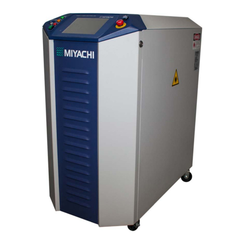
Miyachi MG3D User manual

Original Version: German Translation of Original Version Version: 1.6
76609409EN-BA-MG3D-V1_6.docx 1/82 2010-08-02
MIYACHI EUROPE CORPORATION
www.miyachieurope.com
Lindberghstr. 1 D-82178 Puchheim
Tel. +49-89-839403-0 Fax: +49-89-839403-10
Operating Instructions
MG3D
Digital Measuring Unit
Annex: Safety Regulations
General References on Resistance Welding
Contact Addresses
Order number: Year:
Serial number:

Operating Instructions MG3 Digital
76609409EN-BA-MG3D-V1_6.docx 2/82 2010-08-02
Versions
Version Date Basis of revision
1.0 2002-11 new
1.01 2003-04 Corrections
1.02 2003-07 Software changes
1.03 2003-11 Plug assignment / Indices
1.03a 2004-02 Only English corrections
1.03b 2004-05 Checked CompactFlash
1.03c 2004-09 Only Czech corrections: Screenshots
1.1 2004-11 CanOpen; Pressure/Force; Measurement values; field bus
1.1a 2005-03 Miyachi-Peco
1.2a 2005-09 Safety regulations separate and div. small changes
1.3 2006-05 Diagrams 6.10 added, declaration by the manufacturer
1.3a 2007-04 Declaration of Conformity
1.3b 2008-07 Symbols changed
1.4 2009-09 New design (Spanish only)
1.5 2010-03 Flow diagrams new
1.6 2010-08 CE new Machinery Directives
Copyright ©2010: Miyachi Europe GmbH
All rights reserved. The products named in this manual are only used for identification purposes and may be
trademarks or registered trademarks of the respective companies.

Operating Instructions MG3 Digital
Table of Contents
76609409EN-BA-MG3D-V1_6.docx 3/82 2010-08-02
Table of Contents
1General Information ........................................................................... 5
1.1Declaration of Conformity............................................................................... 5
2Technical Description.......................................................................... 6
2.1Design and Mode of Action.............................................................................. 6
2.2Technical Data ................................................................................................ 7
2.3Maximum Cycle and Memory Times ................................................................ 8
3Commissioning ................................................................................. 12
3.1Connecting the Components ......................................................................... 13
3.1.1Description of the Connectors.......................................................................................13
3.1.2Connector Pin Assignment of Inputs & Outputs ............................................................14
3.1.2.1Connector X54 (Outputs) ..................................................................................................14
3.1.2.2Connector X55 (Inputs) .................................................................................................... 15
3.1.2.3Connector X38 (I/O Outputs) ............................................................................................ 16
3.1.2.4Connector X38 (I/O Inputs)............................................................................................... 17
3.1.2.5Connector X51 (RS232) / Baud rate ................................................................................... 17
3.1.2.6Connector X60 and X61 (CANopen).................................................................................... 18
3.1.3Establishing Connections for Voltage Measurement......................................................19
3.1.4Establishing Connections for Displacement Measuring .................................................20
3.1.5Establishing Connections for Displacement Measurement ............................................21
3.2Initial Commissioning................................................................................... 22
3.2.1Preconditions................................................................................................................22
3.2.2Starting-up ...................................................................................................................22
4Operation.......................................................................................... 23
4.1Measuring Instrument MG3D – What is What?.............................................. 23
4.1.1LED Status Displays ......................................................................................................23
4.1.2Screen (Display) ...........................................................................................................24
4.1.2.1Display Windows – Quadrant 1 to 4.................................................................................... 25
4.1.2.2Menu Bar........................................................................................................................25
4.1.2.3Program Display ..............................................................................................................25
4.1.2.4Measuring Mode............................................................................................................... 25
4.1.2.5Status Bar.......................................................................................................................25
4.1.3Board Slot for Compact Flash Card or MicroDrive..........................................................26
4.1.4Knob/pushbutton Combination.....................................................................................26
4.1.5UNDO Function .............................................................................................................26
4.2Menu Structure............................................................................................. 27
5How to …? ........................................................................................ 28
5.1Carry out a General Set-up ........................................................................... 28
5.2Measuring current and voltage ..................................................................... 32
5.3Conducting Measurements With “Shunt”...................................................... 35
5.4Changing Over Between Single and Continuous Measurement...................... 37
5.5Configuring Display Window for the Various Types of Measurement Categories38
5.6Displacement Measuring (digital or analog) ................................................. 39
5.7Measuring Pressure or Force ........................................................................ 41
5.8Determining Limit Values.............................................................................. 42
5.9Generating Reference Waveforms and Envelope Waveforms ........................ 43

Operating Instructions MG3 Digital
Table of Contents
76609409EN-BA-MG3D-V1_6.docx 4/82 2010-08-02
5.10Copying, saving and loading Programs and Parameters ............................... 50
5.11Counting Measurements ............................................................................... 52
5.12Viewing and Saving Measuring Waveforms................................................... 53
5.13Printing Measurement Values ....................................................................... 57
5.14Determining and Changing Password ........................................................... 58
5.15Configuring the Logger ................................................................................. 59
5.16Parameter Overview Display......................................................................... 61
5.17Analyzing Accept-Reject Ratio ...................................................................... 61
5.18Monitoring Statistical Values ........................................................................ 62
5.19Having Limit Values Determined Statistically................................................ 64
5.20Transferring Data to PC/Laptop.................................................................... 66
5.21Creating a Screenshot of the Current Display ............................................... 66
5.22Registering the Device.................................................................................. 66
6Integration in Automated Installations ............................................ 67
6.1Flow Chart Channel 1 or Channel 2 Alone ..................................................... 67
6.2Flow Chart Channel 1 and Channel 2 Parallel................................................ 68
6.3Flow Chart Channel 1 and Channel 2 Parallel, but Current 1 and Current 2 do
not Overlap................................................................................................... 69
6.4Flow Chart Channel 1 or Channel 2 alone, With Too Short Measuring Interval70
6.5Flow Chart Channel 1 and Channel 2 With Parallel Measuring Within the
Evaluation Time of the Respective Channel That Measures First................... 71
6.6Flow Chart Parts Detection and Current Measuring....................................... 72
6.7Flow Chart Part Detection and Current Measuring Parallel ........................... 73
6.8Flow Chart Measuring and External Selection ............................................... 74
6.9Connection to field bus system ..................................................................... 74
6.10Flow Chart 2 channel part detection with current......................................... 75
6.10.1Fault Example Flow Chart part detection with current ..................................................76
7Appendix .......................................................................................... 77
7.1Error messages............................................................................................. 77
7.2Accessories................................................................................................... 78
7.2.1MG3 Digital ...................................................................................................................78
7.2.2MG3 Digital – W1 ..........................................................................................................78
7.2.3MG3 Digital – W2 ..........................................................................................................78
7.3Enclosures .................................................................................................... 79
7.3.1Connection diagram, Interface MG3D, 767.00590 E......................................................79
7.3.2Connection diagram, X38 (Inputs / Outputs), 767.00 591 E........................................80
8Indexes ............................................................................................ 81
8.1Figures.......................................................................................................... 81
8.2Tables........................................................................................................... 81
8.2.1Headwords....................................................................................................................82

Operating Instructions MG3 Digital
General Information
76609409EN-BA-MG3D-V1_6.docx 5/82 2010-08-02
1General Information
Information about copyrights, protection rights, symbols, safety regulations,
usage location conditions and notes on resistance welding can be found in the
annex of the operating instructions.
Please read this information carefully before using the individual elements of
the AWS welding system.
Information
These device-specific operating instructions should help you familiarize yourself with
the unit and take advantage of its application possibilities when used as directed.
The Operating Instructions contain important notes to help operate the unit safely,
properly, and economically.
Observing the notes will help avoid risks, decrease repair costs and down times, and
enhance reliability and the service life of the unit.
1.1 Declaration of Conformity

Operating Instructions MG3 Digital
Technical Description
76609409EN-BA-MG3D-V1_6.docx 6/82 2010-08-02
2Technical Description
2.1 Design and Mode of Action
Measuring instrument MG3 comprises:
Operator and
display module (Display)
PCB holder and
housing with built-in power
supply
The housing dimension is 1/2 x 19 in. The MG3 can also be supplied in a 19 in. housing
then offering space for an additional control unit.
Data transfer between display unit and PCB holder is made through a CAN interface.
In its standard version, measuring instrument MG3 Digital is equipped
with a 2-channel current-measuring and voltage-measuring card with appropriate internal
periphery in a portable housing.
A combined path-, force-, and temperature-measuring card can supplement the standard
version. Please contact our sales department for further details.
After applying mains, the measuring instrument MG3 Digital detects existing plug-in cards
by plug & plays and configures itself automatically during the boot process.
Individual operator configurations remain stored even when the instrument has been
switched off.
MG3 Digital - Process Sentry

Operating Instructions MG3 Digital
Technical Description
76609409EN-BA-MG3D-V1_6.docx 7/82 2010-08-02
The values of the last 2.500 welds are stored temporarily in a battery-buffered memory
module. If this memory is full the complete measurement data packet is written onto the
compact flash card as log file.
In the standard version, parameters prepared for one measurement from 99 welding-
control programs can be monitored via a program number interface. Miyachi Europe
GmbH multiple program controls, too, are equipped with the corresponding interface.
Output of the selected parameters of each welding to a commercially available is possible.
For that purpose, connect the printer to connector X51 (RS232 interface). In the printer
menu, set the printer format to numeric for all measurements.
Operation of the instrument through a knob/push button combination.
2.2 Technical Data
Instrument type MG3 Digital
Digital measuring and monitoring instrument
for resistance-welding installations
Program monitoring 99 programs, internal or external program
selection, extensible
Measuring functions AC and DC, effective (r.m.s.) current value,
peak value of current, charge (I x t) and
further effective voltage value,
peak value of voltage, voltage integral (u x t)
and further power in variances, energy
resistance in variances, weld time (ms)
Counter Up- and down-counter with prewarning and
final value signal output
Measuring range current Coil x 1:
2–5–20–100–500 kA peak value
Coil x 10:
0.2–0.5–2–10–50 kA peak value
Measuring range voltage 0.5–2.5–10–50 V peak value
Measurement accuracy ±1.5 % of upper limit of effective range for
current and voltage
Minimum measurable current Is±3 % for power. 10 % from measuring
range, (for lesser currents special toroid coil
10-fold)
Maximum measurable current time Approx. 2000 ms at DC, approx. 5000 ms at
AC
Minimum measurable current time Approx. 1 ms
Sampling rate (V, I) = 100 kHz per channel, simultaneous
sampling V, I of each channel
Graphic Resolution
Current/Voltage
Pressure/Force
Distance
measure time <= 50 msec: resolution 40
points per msec
measure time > 50 msec: resolution 5 points
per msec
Pressure/Force 10 points/ms
Digital distance 5 points/ms
Measuring interval Variable
Note
The more graphics are displayed, data
through RS232 and limit value and envelope
curves are monitored, the longer the
measuring interval.
Flattest permissible current rise di/dt ≥2 A/ms at measuring range 2 kA. In
the higher measuring ranges correspondingly
more
Limit value setting Independently from each other for the upper
and lower limit value across the entire
measuring range

Operating Instructions MG3 Digital
Technical Description
76609409EN-BA-MG3D-V1_6.docx 8/82 2010-08-02
Prewarning setting Independently from each other for the upper
and lower prewarning value across the entire
measuring range
Graphic display QVGA, 320 x 240 pixel
Optical display 8-fold via front LED
Outputs Analog output for current on current-
measuring card
Further control outputs see terminal diagram
Inputs 2-fold current and voltage channel,
program selection, CAN, RS232.
Further control inputs see terminal diagram
Mains voltage and frequency
90-260 Volt, ±10 %,
50-60 Hz, switching power supply
Power consumption 60 W
Ambient temperature 0 °C to 40 °C
Relative humidity max. 70%
Dimensions ½ 19“: (WxHxD) 280 x 140 x 340 mm
(Opt. 19”, 3HU)
Weight ca. 5.3 kg, (approx. 11.7 lbs)
2.3 Maximum Cycle and Memory Times
Conditions:
1000 measurements each time with consistent time, voltage, current. No limit value, pre-
warning or overrun outputs should be activated.
Validity:
Program versions
Display V1.2.7
PPC V1.119
DSP V1.4
Information:
These specifications only apply to signal-channel measurements. The recorded cycle time
is doubled for parallel measurement.
Printing via the RS232 is deactivated.
The counter is activated.
2 x pre-warning and limit values are monitored.
Trigger = 1.5%, Filter = off, Envelope waveform = off.
Maximum cycle:
The maximum cycle is the largest possible number of complete welding sequences in a
minute.
The table illustrates the cycle time (above) in ms and the maximum cycles per minute
(below).

Operating Instructions MG3 Digital
Technical Description
76609409EN-BA-MG3D-V1_6.docx 9/82 2010-08-02
Maximum cycle for AC current
All specifications for active ready-output-inquiries.
Current display AC current in [periods] 50Hz
Measuring time 1 per. 2 per. 6 per. 13 per. 25 per.
Quadrant 1-4 numerical
Logging = on 125 ms
480 140 ms
428 230 ms
260 360 ms
166 600 ms
100
Quadrant 1-4 numerical
Logging = off 120 ms
500 140 ms
428 230 ms
260 360 ms
166 600 ms
100
Quadrant 1-4 graphical
I(1),U(2),P(3),W(4)
Logging = off
1630 ms
36 1670 ms
35 1750 ms
34 1910 ms
31 2190 ms
27
34Quadrant 1-4 SPC chart
Logging = off 210 ms
285 220 ms
272 230 ms
260 340 ms
176 590 ms
101
Analysis window
Logging = on 200 ms
300 220 ms
272 260 ms
230 420 ms
142 630 ms
95
Logging window
Logging = on
Last
300 ms
200 380 ms
157 440 ms
136 500 ms
120 680 ms
88
Logging window
Logging = on
All
390 ms
153 430 ms
139 470 ms
127 500 ms
120 650 ms
92
Graphic display
(waveform I)
Logging = on
550 ms
109 610 ms
98 640 ms
93 790 ms
75 1100 ms
54
Graphic display
(waveforms I/U/P/W)
Logging = on
1580 ms
37 1650 ms
36 1690 ms
35 1840 ms
32 2140 ms
28
Tbl. 1: Maximum cycle for AC – active
Maximum cycle for DC current
All specifications for active ready-output-inquiries.
Current display DC current in [ms]
Measuring time 23 ms 50 ms 100 ms 250 ms 500 ms
Quadrant 1-4 numerical
Logging = on 130 ms
461 170 ms
352 190 ms
315 340 ms
176 602 ms
99
Quadrant 1-4 numerical
Logging = off 126 ms
476 170 ms
352 190 ms
315 340 ms
176 602 ms
99
Quadrant 1-4 graphical
I(1),U(2),P(3),W(4)
Logging = off
1635 ms
36 1672 ms
35 1710 ms
34 1870 ms
32 2170 ms
27
Quadrant 1-4 SPC chart
Logging = off 130 ms
461 180 ms
333 210 ms
285 350 ms
171 620 ms
96
Analysis window
Logging = on 220 ms
272 240 ms
250 280 ms
214 400 ms
150 630 ms
95
Logging window
Logging = on
Last
250 ms
240 340 ms
176 380 ms
157 490 ms
122 680 ms
88
Logging window
Logging = on
All
390 ms
153 420 ms
142 470 ms
127 500 ms
120 660 ms
90
Graphic display
(waveform I)
Logging = on
550 ms
109 610 ms
98 640 ms
93 790 ms
75 1100 ms
54
Graphic display
(waveforms I/U/P/W)
Logging = on
1580ms
37 1650ms
36 1690ms
35 1840ms
32 2140ms
28
Tbl. 2: Maximum cycle for DC - active

Operating Instructions MG3 Digital
Technical Description
76609409EN-BA-MG3D-V1_6.docx 10/82 2010-08-02
Maximum cycle for AC current
All specifications without active ready-output-inquiries.
Current display AC current in [periods] 50Hz
Measuring time 1 per. 2 per. 6 per. 13 per. 25 per.
Quadrant 1-4 numerical
Logging = on 140 ms
428 154 ms
398 253 ms
237 396 ms
151 660 ms
91
Quadrant 1-4 numerical
Logging = off 132 ms
454 154 ms
398 253 ms
237 396 ms
151 660 ms
91
Quadrant 1-4 graphical
I(1),U(2),P(3),W(4)
Logging = off
1793 ms
33 1837 ms
32 1925 ms
31 2101 ms
28 2409 ms
24
Quadrant 1-4 SPC chart
Logging = off 221 ms
271 242 ms
247 253 ms
237 374 ms
160 649 ms
92
Analysis window
Logging = on 220 ms
272 242 ms
247 286 ms
209 462 ms
129 693 ms
86
Logging window
Logging = on
Last
330 ms
181 418 ms
143 484 ms
123 550 ms
109 748 ms
80
Logging window
Logging = on
All
429 ms
139 473 ms
126 517 ms
116 550 ms
109 715 ms
83
Graphic display
(waveform I)
Logging = on
605ms
99 671ms
89 704ms
85 869ms
69 1210ms
49
Graphic display
(waveforms I/U/P/W)
Logging = on
1738ms
34 1815ms
33 1859ms
32 2024ms
29 2354ms
25
Tbl. 3: Maximum cycle of AC - without
Maximum cycle for DC current
All specifications without active ready-output-inquiries.
Current display DC current in [ms]
Measuring time 23 ms 50 ms 100 ms 250 ms 500 ms
Quadrant 1-4 numerical
Logging = on 143 ms
419 187 ms
320 209 ms
287 374 ms
160 662 ms
90
Quadrant 1-4 numerical
Logging = off 138 ms
434 187 ms
320 209 ms
287 374 ms
160 662 ms
90
Quadrant 1-4 graphical
I(1),U(2),P(3),W(4)
Logging = off
1799 ms
33 1839 ms
32 1881 ms
31 2057 ms
29 2387 ms
25
Quadrant 1-4 SPC chart
Logging = off 143 ms
419 198 ms
303 231 ms
259 385 ms
155 682 ms
87
Analysis window
Logging = on 242 ms
247 264 ms
227 308 ms
194 440 ms
136 693 ms
86
Logging window
Logging = on
Last
275 ms
218 374 ms
160 418 ms
143 539 ms
111 748 ms
80
Logging window
Logging = on
All
429 ms
139 462 ms
129 517 ms
116 550 ms
109 726 ms
82
Graphic display
(waveform I)
Logging = on
605 ms
99 671 ms
89 704 ms
85 869 ms
69 1210 ms
49
Graphic display
(waveforms I/U/P/W)
Logging = on
1738 ms
34 1815 ms
33 1859 ms
32 2024 ms
29 2354 ms
25
Tbl. 4: Maximum cycle of DC - without

Operating Instructions MG3 Digital
Technical Description
76609409EN-BA-MG3D-V1_6.docx 11/82 2010-08-02
Logging memory times:
Saving on a CompactFlash card with full buffer, approx. 2500 numerical measuring
values, duration approx. 50 s with empty CompactFlash card.
Saving on MicroDrive with full buffer, approx. 2500 numerical measuring values, duration
approx. 50 s.
Program selection loading times:
Internal selection:
Quadrant 1-4 graphical I(1),U(2),P(3),W(4) duration approx. 3000 ms.
Quadrant 1-4 numerical duration approx. 600 ms.
External selection:
Quadrant 1-4 numerical Quadrant 1-4 graphical
I(1),U(2),P(3),W(4)
Main image renewal = on
approx. 600 ms approx. 3000 ms
Main image renewal = off
approx. 50 ms approx. 50 ms

Operating Instructions MG3 Digital
Commissioning
76609409EN-BA-MG3D-V1_6.docx 12/82 2010-08-02
3Commissioning
Measuring instrument MG3 Digital is supplied with a fixed stirrup for setting up the
equipment.
The tilt angle of the measuring instrument front panel can be adjusted by means the
stirrup for taking a non-dazzling reading of the screen.
Fig. 1: MG3Digital with stirrup
Remove measuring instrument MG3 Digital from the packing and set it up at the
designated place.
Pull apart both caps at the stirrup's pivot points (Fig. 1).
Adjust desired position.

Operating Instructions MG3 Digital
Commissioning
76609409EN-BA-MG3D-V1_6.docx 13/82 2010-08-02
3.1 Connecting the Components
3.1.1 Description of the Connectors
BCD
OUT
X56
BCD
IN
X57 CAN
X53 RS232
X51
X38
X31
X32
X33
X13
X21
X14
X22
X55 X54
USB
UK1
I/U DSP Board
I/O* WKT*
UK2
IK1
IK2
2345 6 7
8
9
10
11
12131415
1
17
16
CANopen
X13
X60
X61
18
19
Fig. 2: Connectors on the housing rear side
* optional plug-ins
No. Connector Function
1 Mains Rubber connector for mains cable.
Check mains voltage on type designation plate.
2 USB No usage
3 X56 Outputs for program number (set BCD or binary code accordingly,
1...99 with a standard device)
See enclosures: Connection diagram 767.00590
4 X55 Control inputs from peripheral equipment
5 X54 Control outputs to peripheral equipment
6 X38 (opt.) Inputs and outputs extended I/O
7 X31 (opt.) Connecting terminal for position-encoding system (2-fold) and force-
sensing device
8 X13 UK1 Input channel 1 for voltage measurement
9 X21 IK1 Input channel 1 for current measurement
10 X14 UK2 Input channel 2 for voltage measurement
11 X22 IK2 Input channel 2 for current measurement
12 X32 X33 No usage
13 X51 RS232 interface (e.g. to serial printer or PC)
14 X53 No usage
15 X57 Outputs for program number (set BCD or binary code accordingly,
1...99 with a standard device)
See enclosures: Connection diagram 767.00590
16 ON-OFF switch for mains voltage
17 Miniature fuses
18 X60 CANopen IN
19 X61 CANopen OUT

Operating Instructions MG3 Digital
Commissioning
76609409EN-BA-MG3D-V1_6.docx 14/82 2010-08-02
3.1.2 Connector Pin Assignment of Inputs & Outputs
The outputs always represent the last measurement. They will be set or cleared only after
a new measurement.
3.1.2.1 Connector X54 (Outputs)
Pin Name Channel Function
1 Ready 1 and 2
Control unit ready and can receive data. Ready flag skipped
during counter or measured value reset, during boot
procedure, or by HIGH signal at control input NOT READY,
measurement reset, data transfer
2 Current 1
Signal waiting until manually set measuring time ends after
acquired current input or as long as an active current signal
lasts that is registered in the course of the measuring time.
3 WARN min. 1 and 2
Output of prewarning monitoring minimum.
4 WARN max. 1 and 2
Output of prewarning (WARN) monitoring maximum.
5 Limit value
min.
1 and 2
Output of limit value monitoring minimum.
6 Counter limit
1 and 2
Signal waiting when counter final value is reached till counter
reset.
7 REJECT 2
Signal waiting as soon as monitored parameter is outside of
limit value tolerance.
8 Current 2
Signal waiting until manually set measuring time ends after
acquired current input or as long as an active current signal
lasts that is registered in the course of the measuring time.
14 ACCEPT 1
Signal waiting as long as parameters monitored with limit
values are within limit value tolerance.
15 REJECT 1
Signal waiting as soon as monitored parameter is outside of
limit value tolerance.
16 Overflow 1 and 2
Signal waiting if a set measuring range is exceeded by the
measured parameter.
17 Zero current 1
Signal is activated:
a) after external trigger signal if no current is measured during
this.
b) after part detection subsequent to interrupted part
evaluation (valid part detection).
c) if trigger source “0 penetration“ or “Force trigger“ is
activated and no current is measured.
Signal is deactivated:
a) at beginning of measurement
b) with signal at measuring value reset input
18 Limit value
max.
1 and 2
Output of limit value monitoring maximum.
19 Counter
WARN
1 and 2
Signal waiting when counter reached prewarning value till
counter reset.
20 ACCEPT 2
Signal waiting as long as parameters monitored with limit
values are within limit value tolerance.
21 Zero current 2 Signal is activated:
a) after external trigger signal if no current is measured during
this.
b) after part detection subsequent to interrupted part
evaluation (valid part detection).
c) if trigger source “0 penetration“ or “Force trigger“ is
activated and no current is measured.
Signal is deactivated:
a) at beginning of measurement
b) with signal at measuring value reset input

Operating Instructions MG3 Digital
Commissioning
76609409EN-BA-MG3D-V1_6.docx 15/82 2010-08-02
3.1.2.2 Connector X55 (Inputs)
Pin Name Channel Function
5 Clear
ACCEPT
outputs, set
faults
1 and 2
T
his signal disables all ACCEPT outputs; all limit, REJECT, and
prewarning (WARN) outputs (fault outputs) are set.
8 Save log-file 2
9 Counter
reset
1
A signal sets counter to its initial value.
10 Measuremen
t reset and
outputs
cleared
2
Displayed measured values are set to zero with falling edge
and outputs are cleared.
12 Hold 1
No arriving measured values of a succeeding welding are
accepted after a signal. If Hold signal is dropped again, the
measured values are read in again starting with a new
welding.
13 Trigger 1
Parameter values received after signal are acquired but
evaluated and transferred only after trigger signal has become
LOW again with falling edge. Acquired parameter values
during continuously waiting trigger signal are overwritten by
newly arriving measurements without evaluation and transfer.
17 Not ready 1 and 2
A signal disables parameter value acquisition; ready output at
X54, pin 1 goes to LOW.
18 Set ACCEPT
outputs,
clear faults
1 and 2
T
his signal disables all REJECT and limit value outputs; all
ACCEPT outputs are set.
21 Save log-file 1
22 Counter
reset
2
A signal sets counter to its initial value.
23 Measuremen
t reset and
outputs
cleared.
1
Displayed measured values are set to zero with falling edge
and outputs are cleared.
24 Hold 2
No arriving measured values of a succeeding welding are
accepted after a signal. If Hold signal is dropped again, the
measured values are read in again starting with a new
welding.
25 Trigger 2
Parameter values received after signal are acquired but
evaluated and transferred only after trigger signal has become
LOW again with falling edge. Acquired parameter values
during continuously waiting trigger signal are overwritten by
newly arriving measurements without evaluation and transfer.

Operating Instructions MG3 Digital
Commissioning
76609409EN-BA-MG3D-V1_6.docx 16/82 2010-08-02
3.1.2.3 Connector X38 (I/O Outputs)
Pin Name Chann.
Function
3
4
Sinking Path min.
Sinking Path
max.
1
1 Depending on setup default; becomes active if the
currently measured sinking path min./max. is
exceeded or remains under
5
6
Sinking Path min.
Sinking Path
max.
2
2 see above
7 Prewarn Dist. S3 1
8 Prewarn Dist. S6 2
9 Sinking 2 Accept
2
2 Output enabled if sinking path 2 is ACCEPT
10 Sinking 1 Accept
1
1 Output enabled if sinking path 1 is ACCEPT
11 Pressure/Force
reject
1
12 Pressure/Force
accept
1
13 Pressure/Force
reject
2
14 Pressure/Force
accept
2
17
31
Path Abort
current High
Path Abort
current Low
2
2
Output active on High; is enabled if cutoff value is
exceeded.
Output active on Low; is enabled if cutoff value is
exceeded.
18,
21 Plus terminal (+)
Common plus terminal (+) for PIN:
14, 13, 11, 12, 10, 9, 8, 7, 6, 5, 4, 3, 30, 29, 28, 27,
26, 25, 24, 23
19 Common (+) 1 1 Common plus terminal 10 – 30 V for PIN 16 and 20.
20
16
Path Abort
Current High
Path Abort
Current Low
1
1
Output active on High; is enabled if cutoff value is
exceeded.
Output active on Low; is enabled if cutoff value is
exceeded.
25 Parts Detection
Low active
1 if limit values are not reached or exceeded, then this
output is switched off (pressure switch control unit),
26 Parts Detection
Low active 2
2 if limit values are not reached or exceeded, then this
output is switched off (pressure switch control unit),
27
28
Path Parts
Detection min.
Path Parts
Detection max.
1
1
Depending on setup default; becomes active if the
currently measured parts control path min./max. is
exceeded or remains under.
29
30
Path Parts
Detection min.
Path Parts
Detection max.
2
2
Depending on setup default; becomes active if the
currently measured parts detection path min./max.
is exceeded or remains under.
34 Common (+) 2 Common plus terminal 10 – 30 V for PIN 17 and 34.

Operating Instructions MG3 Digital
Commissioning
76609409EN-BA-MG3D-V1_6.docx 17/82 2010-08-02
3.1.2.4 Connector X38 (I/O Inputs)
Pin Name Function
22 Ground connection Common connection of the inputs.
35 n/c
36 n/c
37 n/c
38 n/c
39 Reference run part
detection 1 and 2
if this input is active, the reference value is determined
on the next parts detection run without inserted
component
Adjustment: Path-measuring mode to reference
41 n/c
42 n/c
43 n/c
44 n/c
45 Null Sinking 2 Setting = Null Sinking 2 with rising slope, zeroing with
rising slope, cooling time with dropping slope.
46 Null Sinking 1 Setting = Null Sinking 1 with rising slope, zeroing with
rising slope, cooling time with dropping slope.
47 Parts Detection 2 Setting to parts detection = HWScan.
Measured value evaluated and part set to min. 2 – max.
2.
48 Parts Detection 1 Setting to parts detection = HWScan.
Measured value evaluated and part set to min. 1 – max.
1.
49 Start Measure 2 Part detection 2 for sensor 1 started.
50 Start Measure 1 Part detection 1 for sensor 1 started.
3.1.2.5 Connector X51 (RS232) / Baud rate
Pin Name
1 free
2 TxD
3 RxD
4 5V
5 GND
6 free
7 CTS
8 RTS
9 free
Baud rates (bit/s) 9600; 19200; 38400; 57600; 115200
Data bits 8
Start bits 1
Stop bits 1
Parity none
Busy Control no/off

Operating Instructions MG3 Digital
Commissioning
76609409EN-BA-MG3D-V1_6.docx 18/82 2010-08-02
3.1.2.6 Connector X60 and X61 (CANopen)
Connection with standard RS232-extension cable (1:1)
Pin Name Function
1 Free
2 CAN_L Low-level
3 CAN_GND Ground
4 Free
5 CAN_SHLD Circuit shield
6 Free
7 CAN_H High-level
8
9
CAN-Baud rates 1MB/s
800 kB/s
500 kB/s
250 kB/s
125 kB/s
50 kB/s
20 kB/s
10 kB/s

Operating Instructions MG3 Digital
Commissioning
76609409EN-BA-MG3D-V1_6.docx 19/82 2010-08-02
3.1.3 Establishing Connections for Voltage Measurement
If no threaded holes are provided for attaching the voltage measuring cables you may
make them yourselves.
Take care to position the threaded holes as close to the electrodes as possible without
compromising their stability!
Fig. 3: (+) Connection (example)
Fig. 4: (-) Connection (example)
•Connect the red cable (+) terminal to the welding head (+) pole (Fig. 3) at the
position provided for this purpose.
•Connect the black cable (–) terminal to the welding head (-) pole (Fig. 4) at the
position provided for this purpose.
•Insert the 5-pole male connector in socket X13 (Fig. 2/8)
or X14 (Fig. 2/10).

Operating Instructions MG3 Digital
Commissioning
76609409EN-BA-MG3D-V1_6.docx 20/82 2010-08-02
3.1.4 Establishing Connections for Displacement Measuring
Coils of various types for current measurement are provided.
The coil amplification factor is of particular importance. Please take the amplification
factor (1:1 or 1:10) from the type designation plate of the coil purchased by you or the
technical data of the coil (see separate data sheet).
There are two examples for coils in Fig.5 and Fig. 6.
Fig. 5: Flap toroid coil (example) with
(+) side marking
Fig. 6: Toroid coil (example) with (+)
side marking
Direction of current, and therefore, coil installation direction is important in order to
ensure correct current reading.
Ensure that the correct coil fitting position is selected during installation!
Fig. 7: Application example with a built-in flap toroid coil
•Install the flap toroid coil or toroid coil in the (+) line of the current source (Fig. 7).
Ensure that the (+) side of the coil show points in the direction of the current source
(+) terminal.
•Connect the cable for current measurement to the flap toroid coil or toroid coil.
•Insert the 3-pole male connector in socket X21 (Fig. 2/9)
or X22 (Fig. 2/11).
This manual suits for next models
1
Table of contents
Other Miyachi Measuring Instrument manuals
Popular Measuring Instrument manuals by other brands

AquaLabo
AquaLabo Supratec S200 WCS user manual

Power Measurement
Power Measurement 3300 ACM Installation & operation manual

Schäfer
Schäfer iQdata RMS 222 user manual

wtw
wtw Turb 2000 Series operating manual

Fuji Electric
Fuji Electric ZFK8 Series instruction manual

Zenner
Zenner zelsius C5-IUF Installation and operating instructions