Ninglu AM706 User manual

Website:www.ninglutech.com
Document:NLT-AM706-SSCN
Edition:V170816
Anemometer AM706
Operation & Installation Manual

Contents
Introduction....................................................................1
System Composition...............................................................................1
Function and Operation (AM706E)...............................4
Display Layout ......................................................................................4
Function..................................................................................................4
Power on/off ....................................................................................4
Brightness........................................................................................4
OK...................................................................................................5
Day/Night Mode...............................................................................5
MODE..............................................................................................5
Arrow Keys......................................................................................6
MENU..............................................................................................6
Wind Alarm.............................................................................................6
Speed Unit..............................................................................................7
Avg Time ................................................................................................7
Input Show..............................................................................................8
Language................................................................................................8
Back Color..............................................................................................8
Dig Color.................................................................................................8
Default....................................................................................................9
Send Ture...............................................................................................9
Data transmission for NMEA0183...........................................................9
Main Unit Output --MWV .................................................................9
GPS Data Input--RMC...................................................................10
GPS Data Input--VTG....................................................................10
Speedlog Data Input--VBW ...........................................................11
Speedlog Data Input--VHW...........................................................11
Gyro Data Input--HDT ...................................................................11
Function and Operation (AM706C) ............................12
Display Layout......................................................................................12
Alarm....................................................................................................12
Input and Output...................................................................................13
About NMEA0183 outputs ....................................................................14
Operation..............................................................................................14

Normal display mode............................................................................15
Set the dividing value of wind alarm .....................................................16
Set the first level alarm value................................................................17
Set the second level alarm value..........................................................18
Gust mode............................................................................................19
Set GST mode......................................................................................19
Printed time interval..............................................................................20
Specification ................................................................21
Maintenance.................................................................23
Main Unit ..............................................................................................23
Sensor Part...........................................................................................23
Calibration....................................................................24
Installation....................................................................25
Installation of Main Unit AM706E..........................................................25
Installation of Main Unit AM706C..........................................................26
Power Adapter Mounting ...............................................................26
Installation of Wind sensor AM706S.....................................................27
Wind Vane and Wind Cup Installation...........................................27
Integral Installation ........................................................................28
1st Alarm Unit(AM706A1)................................................................29
2nd Alarm unit (AM706A2).....................................................................30
Wiring Explanation......................................................31
System View.......................................................................................31
AM706E Wiring Explanation.......................................32
Wiring Diagram of AM706E Back Cover...............................................32
System External Wiring Diagram of AM706E .......................................33
AM706C Wiring Explanation.......................................34
System External Wiring Diagram of AM706C .......................................34
Connection of AM706C and AM706S ...................................................35
Connection of Alarm Distributor............................................................35
Connection of 1st alarm unit AM706A1 .................................................36
Connection of 2nd alarm unit AM706A2.................................................36

Printer...........................................................................37
DPU-414 Specification..........................................................................37
Supplementary wiring for printer DPU-414...........................................37
Printed Format......................................................................................38
Printer setting .......................................................................................39
Repeater .......................................................................39
IR761 Specification...............................................................................40
Operation..............................................................................................40
Connection ...........................................................................................41
Appendix ......................................................................42

1
AM706C
AM706E
Introduction
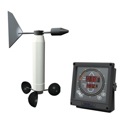
The Marine Anemometer AM706 is a combined instrument for wind speed
and direction. It can measure relative wind speed (accuracy ±5%, min
0.1m/s), relative wind direction (digital display accuracy 1 °, analog display
accuracy 10 °and output accuracy ±1 °). GYRO(HDT), SPEEDLOG(VBW)
or GPS (RMC/VTG) data user can select relative wind mode and true wind
mode.
Main unit AM706E+AM706C can be installed by the table, hanging and flush
mounting methods. Sensor AM706S should be installed in the place
with free wind in the ship.
System Composition
Main Unit AM706E
·Direction Display:Analog and digital display of relative (to the
bow) and true wind direction
·Speed Display:Digital display of relative, true, max and average wind
speed.
Main Unit AM706C
The main unit AM706C receives the signal from
the sensor unit, and displays:
·Relative wind direction
·Relative wind speed
·Maximum wind speed
·First and second level alarm settings
The main unit also output the setting of the wind speed alarm to the alarm
unit.

2
AM706S
AM706A1
Introduction
Sensor unit AM706S
The Sensor unit AM706S includes three parts:
·Wind speed sensor: A rotor with three wind cups.
·Wind direction sensor: A wind vane to drive an absolute
angle sensor unit.
·Junction box: It has a waterproof junction box and a
sensor unit transmitter.
Alarm unit AM706A1&AM706A2
AM706A1 is installed in the CCR (cargo control room).
Light source: LEDs
Light form: flash
Light color:red
Sound source: buzzer
Sound form: continues
Sound decibel: 60dB~85dB(A)
AM706A2 is installed on the cargo deck
Light source: Super bright LEDs
Light form: rotating flash
Light color: red
Sound source: horn
Sound form: continues
Sound decibel: 110dB (A)
AM706A2

3
Introduction
Peripheral equipment
Printer: DPU414, print date, wind speed & direction and so on
Repeater: IR761, redisplay the wind speed & direction
VDR: (vessel data recorder): record data from the main unit

4
Function and Operation (AM706E)
Display Layout
Function
Power on/off
Press the on-off key to turn on /off the system.
Brightness
In Day/Night mode, press the brightness key to adjust the screen
brightness. There are 9 levels for selection.
Power on/off Menu OK Mode
Brightness Arrow keys Day/Night Mode
Wind Direction Digital Display
Wind Speed Digital Display
Operation Keyboard
Wind Direction Analog Display

5
Function and Operation (AM706E)
OK
Press [OK] key to save the settings in the menu and return to the
main screen.
Day/Night Mode
Press the Day/Night mode key to switch the day mode and night
mode.
MODE
Press [MODE] key to select Relative Mode(relative speed + relative
angle + max speed + average speed)and True Mode(relative speed
+ relative angle + true speed + true Angle).
Relative Mode True Mode
Note:The wind grade (see Appendix)can only be shown in relative mode.
The ship speed and heading can be only shown in true mode.

6
Function and Operation (AM706E)
Arrow Keys
In the menu mode, press up/down arrow keys to select the setting
items and press left/right arrow keys to select the setting values.
MENU
Menu Explanation
Item
Range
Default
Wind Alarm
[Off 1~60m/s]
Off
Speed Unit
[m/s km/h knots]
m/s
Avg Time
[1 min 2 min 5 min 10 min]
10 min
Input Show
[Off On]
Off
Language
[English 中文]
English
Back Color
[Light-Blue Blue Black]
Light-Blue
Dig Color
[Yellow in Blue Green in Black White in
Black]
Yellow in Blue
Default
[Off Reset]
Off
Send Ture
[Yes No]
No
Wind Alarm
Set the relative wind speed alarm values. When the relative wind speed is
larger than the relative wind alarm value, the system will give the alarm signal
after 30s with beep and speed numbers become red color and flash. Press
any key to mute the beep but the relative speed numbers are still in red color

7
Function and Operation (AM706E)
and flash. When the relative wind speed is less than the relative wind alarm
value, the relative speed numbers return to white color and not flash. Then
the system will be working normally.
Press up/down arrow keys to select the item ‘Wind Alarm’and press left/right
arrow keys to set the wind alarm values.
Setting Range is 1~60m/s and default is Off
Speed Unit
Set the wind speed unit. Press up/down arrow keys to select the item ‘Speed
Unit’and press left/right arrow keys to select speed unit.
1~60m/s and default is Off
Setting Range is m/s, km/h and knots and default is m/s.
Avg Time
Set the computing period of the max speed and average speed. Press
up/down arrow keys to select the item ‘Avg Time’and press left/right arrow
keys to set the period.
Setting Range is 1 min, 2 min, 5 min and 10 min and default is 10 min.

8
Function and Operation (AM706E)
Input Show
Set the input display of Gyro, Speedlog and GPS. Press up/down arrow keys
to select the item ‘Input Show’and press left/right arrow keys to select on and
off.
Setting Range is Off and On and default is Off.
Language
Set the system language. Press up/down arrow keys to select the item
‘Language’and press left/right arrow keys to select English and Chinese.
Setting Range is English and 中文 and default is English.
Back Color
Set the background color. Press up/down arrow keys to select the item ‘Back
Color’and press left/right arrow keys to select the colors.
Setting Range is Light-Blue, Blue and Black and default is Light-Blue.
Dig Color
Set the window and number colors. Press up/down arrow keys to select the
item ‘Dig Color’and press left/right arrow keys to select the colors.
Setting Range is Yellow in Blue, Green in Black and White in Black and
default is Yellow in Blue.

9
Function and Operation (AM706E)
Default
Reset the system. Setting Range is Off and Reset, and default is Off.
Send Ture
Set the transmitted relative or true sentence. Yes is to transmit relatvie and
true sentence and No is to transmit relative sentence.
Data transmission for NMEA0183
Main Unit Output --MWV
$--MWV, x.x , a , x.x , a , A*hh<CR><LF>
1 23456
1) Wind angle, 0 to 359 degrees
2) Reference, R = Relative, T = Ture
3) Wind Speed
4) Wind Speed Units, K=km/h / M=m/s / N=knots
5) Status, A = Data Valid, V = Data invalid
6) Checksum

10
Function and Operation (AM706E)
GPS Data Input--RMC
$--RMC, hhmmss.ss,A,llll.ll,a,yyyyy.yy,a,x.x,x.x,xxxxxx,x.x,a,a*hh<CR><LF>
12 345 67 8 9 10
1) UTC Time
2) Status, A=Data valid, V = Navigation receiver warning
3) Latitude,N or S
4) Longitude,E or W
5) Speed over ground, knots
6) Course Over Ground, degrees true
7) Date:ddmmyy
8) Magnetic Variation, degrees,E or W
9) Mode Indicator
10) Checksum
GPS Data Input--VTG
$--VTG, x.x,T , x.x,M , x.x,N , x.x,K , a*hh<CR><LF>
1 2 3456
1) Course over ground, degree true
2) Course over ground, degree magnetic
3) Speed over ground, knots
4) Speed over ground, km/h
5) Mode indicator,A=Autonomous mode
D=Differential mode
E=Estimated(dead reckoning)mode
M=Manual input mode
S=Simulator mode
N=Data not valid
6) Checksum value

11
Function and Operation (AM706E)
Speedlog Data Input--VBW
$--VBW, x.x , x.x , A , x.x , x.x , A , x.x , A , x.x , A*hh<CR><LF>
12 3 4 5 678910 11
1) Longitudinal water speed, Knots
2) Transverse water speed, Knots
3) Status:water speed, A=data valid, V=data invalid
4) Longitudinal ground speed, Knots
5) Transverse ground speed, Knots
6) Status:ground speed, A=data valid, V=data invalid
7) Stern transverse water speed, Knots
8) Status:stern water speed, A=data valid, V=data invalid
9) Stern transverse ground speed, Knots
10) Status:stern ground speed, A=data valid, V=data invalid
11) Checksum value
Speedlog Data Input--VHW
$--VHW, x.x,T , x.x,M , x.x,N , x.x,K*hh<CR><LF>
12 3 4
(1) Heading, degrees True
(2) Heading, degrees Magnetic
(3) Speed, knots
(4) Speed, km/hr
Gyro Data Input--HDT
$--HDT, x.x , T * hh<CR><LF>
123
1) Heading, degree true
2) T = true
3) Checksum value

12
Function and Operation (AM706C)
Display Layout
Alarm
Form
LED
Alarm imformation
Signal
Error alarm
Shows “ERR” when the operator unit receives no
signal or the signal is not a NMEA message.
Shows “_ _ _” when the message is incorrect
Shows “….” when receiving other message
Power supply
Power drops alarm
When one of the two power channels is lost, the
buzzer will alarm and press any key to clear the
alarm.
Gust mode
Flashing
When the measured wind speed exceeds the set
alarm value, the digital tube will be flashing, the
buzzer of the main unit and the audible and visual
alarm will start to work. Press any key to remove the
alarm sound.
Red outer ring: Relative wind direction
Orange inner ring: Wind direction range
Big digital tube: Current wind
speed/mode
Wind speed unit
Small digital tube: See operation part
Current mode display
speed/mode
Wind speed unit selection
Mode selection
Single press: Set brightness/ values
Both Press: Inter sleep mode

13
Function and Operation (AM706C)
Input and Output
RMC input baud rate:Automatic reception of 4800、9600、19200、38400bps.
Direction and speed output: 4800bps
GPS input: NMEA0183-RMC (The data input cycle should not exceed 2
seconds)
$--RMC, hhmmss.ss,A,llll.ll,a,yyyyy.yy,a,x.x,x.x,xxxxxx,x.x,a,a*hh<CR><LF>
12 345 67 8 9 10
1) UTC Time
2) Status, A=Data valid, V = Navigation receiver warning
3) Latitude,N or S
4) Longitude,E or W
5) Speed over ground, knots
6) Course Over Ground, degrees true
7) Date:ddmmyy
8) Magnetic Variation, degrees,E or W
9) Mode Indicator
10) Checksum
Main unit output: MWV,to repeater and VDR, etc.
$--MWV, x.x , a , x.x , a , A*hh<CR><LF>
1 23456
1) Wind angle, 0 to 359 degrees
2) Reference, R = Relative, T = Ture
3) Wind Speed
4) Wind Speed Units, K=km/h / M=m/s / N=knots
5) Status, A = Data Valid, V = Data invalid
6) Checksum

14
Function and Operation (AM706C)
About NMEA0183 outputs
The echo data outputs adopt NMEA0183 format complying with IEC61162-1.
Data transmission: serial asynchronous mode, Baud rate 4800, 8 digits, no
parity bit, 1 stop bit.
Operation
〖Sleep mode〗Press [▲] and [▼] at the same time, turn the main unit
into sleep mode. Press any key to remove sleep mode.
〖Backlight〗Press [▲] or [▼] to set backlight of the main unit.
〖Speed unit〗Press [S] on the main unit to inter the “wind speed unit
selection”, then press [▲] or [▼] to select the speed unit. You can choose
“m/s, km/h, kts”.
〖Mode selection〗Press [F] on the main unit to exchange the modes,
normal display mode, AL1 (the first level alarm mode), AL2 (the second level
alarm mode), GST (gust setting mode) and PRE (printed time interval setting
mode).

15
Function and Operation (AM706C)
Normal display mode
The alarm settings are bellow for the current mode display (LED in the
second line).
Setstate
Window Display Status
Setstate
Window Display Status
AL1 on
AL2 on
AL1 AL2 MAX
Light up every 5 seconds
in turn
AL1 off
AL2 on
AL2 MAX
Light up every 5 seconds in
turn
AL1 on
AL2 off
AL1 MAX
Light up every 5 seconds
in turn
AL1 off
AL2 off
MAX long bright
Red outer ring: Relative wind direction
Orange inner ring: Wind direction range
Big digital tube: Current wind speed (relative)
Wind speed unit
Small digital tube: max speed in
measurement period
Current mode display
speed/mode
Wind speed unit selection
Mode selection
Single press: Set brightness/ values
Both Press: Inter sleep mode

16
Function and Operation (AM706C)
Set the dividing value of wind alarm
Press [F] once on the main unit to enter the “wind alarm dividing value
setting”. “dId” is flashing. The first line LEDs show “dId”, then press [▲] or [▼]
to set the dividing value. The second line LEDs show the setting value.
The dividing value here after will be referred to as “X”.
Press [S] on the main unit to to select the speed unit, m/s, km/h, kts. And
press [▲] or [▼] to set the dividing value.
Unit
Set min value
Set max value
Set range
Step
m/s
3
59
AL1~AL2-1
1
km/h
10
214
AL1~AL2-2
2
Kts
5
116
AL1~AL2-1
1
Wind speed unit selection
Mode selection
Dividing settings
Current mode display
Alarm dividing value settings
Wind speed unit
Setting value display
Other manuals for AM706
2
Table of contents
Other Ninglu Measuring Instrument manuals
